Text extracted from the exhibit documents filed with the FCC. Open a document above to read the original.
PRODUCT NAME: BLUETOOTH HEADSET TRADE NAME: FOXCONN, MODEL NO.: FBH-302 Manual Charging Procedure: 1. Connect the USB charging cable into the USB port of charger. 2. Plug‐in the charger into the AC outlet. 3. Connect the charger to the headset charging port. Then the red LED indicated. 4. 1 st time charge should be for at least 2 hours. Once the charging completion the red LED turns off. 5. There is an alternative charging way by using attached USB charging cable to connect the computer USB port directly. Turning the Headset On/Off: 1. To turn the headset on, press MFB 2 seconds until the greed LED on. Then release MFB button. 2. To turn the headset off, press MFB 2 seconds while powering on until the red LED on. Then release MFB button. How easy to wear it on: 1. Insert the earloop into the headset. 2. Wear the open side of headset earloop from the top of ear in place. 3. Turn the headset earloop clockwise or counterclockwise for fitting on left or right ear. 4. Align the microphone with your mouth to get the best reception for the caller. Pairing Procedure: 1. Turn on the Bluetooth feature on your phone. 2. Keep the headset status at power off 3. Press MFB button for more than 4 seconds until the green LED flashed quickly. 4. Perform your Bluetooth phone to discover the headset. 5. Select the “FBH-302“ headset. If prompted for a passkey, enter 0000. 6. When pairing is successful, the indicator on your headset flashes green every five seconds. Your phone will also confirm when pairing is complete. Headset Controls and Indicators Control Action Key Visual Indicator Tone Power On Power Off ON: Press MFB button for 2 seconds Off: Press MFB button for 2 seconds On: Green LED on 1 second Off: Red LED on 1 second 4 rising tones 4 descending tones Pairing Press MFB button for more than 4 seconds Green LED flashes 100ms continuously for 3 minutes 2 rising tones Voice Dial Press MFB button less than 1 second None 1 beep tone Last Number Redial Press MFB button twice None 1 beep tone Call Answer Press MFB button less than 1 second None 2 rising tones Reject Press MFB button twice None 2 descending tones End a Call Press MFB button less than 1 second None 1 beep tone Audio Transfer Press MFB button twice None 1 beep tone Volume Up Volume Down Press Volume Up button less than 1 second for each level Press Volume Down button less than 1 second for each level None None 1 beep tone 1 beep tone Standby Mode None Green LED on 1 second every 5 seconds Connected None Green LED on 1 second only 1 beep tone Disconnected None Red LED on 1 second only Connectable None Green LED on 1 second every 2 seconds FEDERAL COMMUNICATIONS COMMISSION INTERFERENCE STATEMENT This equipment has been tested and found to comply with the limits for a Class B digital device, pursuant to Part 15 of the FCC Rules. These limits are designed to provide reasonable protection against harmful interference in a residential installation. This equipment generates, uses and can radiate radio frequency energy and, if not installed and used in accordance with the instructions, may cause harmful interference to radio communications. However, there is no guarantee that interference will not occur in a particular installation. If this equipment does cause harmful interference to radio or television reception, which can be determined by turning the equipment off and on, the user is encouraged to try to correct the interference by one or more of the following measures: --Reorient or relocate the receiving antenna. --Increase the separation between the equipment and receiver. --Connect the equipment into an outlet on a circuit different from that to which the receiver is connected. --Consult the dealer or an experienced radio/TV technician for help. CAUTION: Any changes or modifications not expressly approved by the grantee of this device could void the user's authority to operate the equipment. This device complies with Part 15 of the FCC Rules. Operation is subject to the following two conditions: (1) this device may not cause harmful interference, and (2) this device must accept any interference received, including interference that may cause undesired operation. RF exposure warning · The equipment complies with FCC RF exposure limits set forth for an uncontrolled environment. The equipment must not be co-located or operating in conjunction with any other antenna or transmitter.
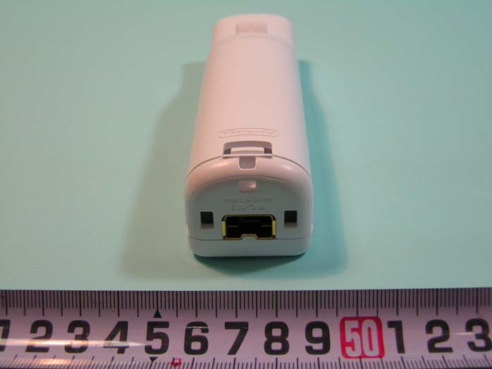
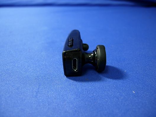
Report No.: 108148R-RFUSP43V01 Page : 1 of 6 Attachment 2 : EUT Detailed Photographs (1) EUT Photo (2) EUT Photo
Foxconn Technology Co., Ltd. FCC ID.: UMBFBH-302 No. 2,Zihyou St., Tucheng City, Taipei Country 236, Taiwan(R.O.C).Tel : 886-2-2268-3466#1154 FCC ID Label The FCC ID and DoC Label will be placed on the equipment as shown in the photograph below.
Report No.: 108148R-RFUSP43V01 Page : 2 of 6 (3) EUT Photo (4) EUT Photo Report No.: 108148R-RFUSP43V01 Page : 3 of 6 (5) EUT Photo (6) EUT Photo Report No.: 108148R-RFUSP43V01 Page : 4 of 6 (7) EUT Photo (8) EUT Photo Report No.: 108148R-RFUSP43V01 Page : 5 of 6 (9) EUT Photo (10) EUT Photo Report No.: 108148R-RFUSP43V01 Page : 6 of 6 (11) EUT Photo
Report No. 108148R-RFUSP43V01 Page: 7 of 73 1.2. Operational Description The EUT is a Bluetooth Headset with built-in 2.4GHz Bluetooth V2.1+EDR transceiver. The number of the channels is 79 in 2402-2480MHz. The device adapts the frequency hopping spread spectrum modulation. The antenna is PIFA antenna and provides diversity function to improve the receiving function. The system receivers have input bandwidths that match the hopping channel bandwidths of their corresponding transmitters and shift frequencies in synchronization with the transmitted signals Frequency hopping spread spectrum systems are not required to employ all available hopping channels during each transmission. The transmitter is presented with a continuous data stream. In addition, a system employing short transmission bursts must comply with the definition of a frequency hopping system and must distribute its 79 channels and over the minimum number of hopping channels (75 channels). The incorporation of intelligence within a frequency hopping spread spectrum system that permits the system to recognize other users within the spectrum band so that it individually and independently chooses and adapts its hopsets to avoid hopping on occupied channels is permitted. The coordination of frequency hopping systems in any other manner for the express purpose of avoiding the simultaneous occupancy of individual hopping frequencies by multiple transmitters is not permitted.
RF Exposure Statement 1. Standard Applicable According to 1.1307 (b)(1), systems operating under the provisions of this section shall be operated in a manner that ensure that the public is not exposed to radio frequency energy level in excess of the Commission’s guideline. 2. Measurement Result: This is a portable device and the max peak output power is 7.84 dBm (EIRP), which is equal to 6.08 mW (EIRP). Lower that low threshold (60/f GHz) mW = 25 mW, d <20 cm general population category. The SAR/MPE measurement is not necessary.
Report No. 108148R-RFUSP43V01 Page: 1 of 74 Test Report Product Name Bluetooth Headset Model No. FBH-302 FCC ID. UMBFBH-302 Applicant Foxconn Technology Co., Ltd. Address No. 2, Zihyou St., Tucheng City, Taipei Country 236, Taiwan(R.O.C) Date of Receipt Aug. 03, 2010 Issued Date Sep. 24, 2010 Report No. 108148R-RFUSP43V01 Report Version V1.0 The Test Results relate only to the samples tested. The test report shall not be reproduced except in full without the written approval of QuieTek Corporation. This report must not be used to claim product endorsement by NVLAP any agency of the U.S. Government Report No. 108148R-RFUSP43V01 Page: 2 of 74 Test Report Certification Issued Date: Sep. 24, 2010 Report No.: 108148R-RFUSP43V01 Product Name Bluetooth Headset Applicant Foxconn Technology Co., Ltd. Address No. 2, Zihyou St., Tucheng City, Taipei Country 236, Taiwan(R.O.C) Manufacturer Hon Hai Precision Industry CO., LTD. Model No. FBH-302 FCC ID. UMBFBH-302 EUT Rated Voltage AC 100-240 V, 50-60 Hz EUT Test Voltage AC 120V/ 60Hz Trade Name FOXCONN Applicable Standard FCC CFR Title 47 Part 15 Subpart C: 2009 ANSI C63.4: 2003 Test Result Complied The Test Results relate only to the samples tested. The test report shall not be reproduced except in full without the written approval of QuieTek Corporation. This report must not be used to claim product endorsement by NVLAP any agency of the U.S. Government Documented By : ( Senior Adm. Specialist / Rita Huang ) Tested By : ( Engineer / Sabrina Tsai ) Approved By : ( Manager / Vincent Lin ) Report No. 108148R-RFUSP43V01 Page: 3 of 74 TABLE OF CONTENTS Description Page 1. GENERAL INFORMATION ...............................................................................................................5 1.1. EUT Description......................................................................................................................................5 1.2. Operational Description...........................................................................................................................7 1.3. Tested System Details..............................................................................................................................8 1.4. Configuration of Tested System ..............................................................................................................9 1.5. EUT Exercise Software ...........................................................................................................................9 1.6. Test Facility ...........................................................................................................................................11 2. CONDUCTED EMISSION ................................................................................................................12 2.1. Test Equipment ......................................................................................................................................12 2.2. Test Setup ..............................................................................................................................................12 2.3. Limits.....................................................................................................................................................13 2.4. Test Procedure .......................................................................................................................................13 2.5. Uncertainty ............................................................................................................................................13 2.6. Test Result of Conducted Emission .......................................................................................................14 3. PEAK POWER OUTPUT ..................................................................................................................16 3.1. Test Equipment ......................................................................................................................................16 3.2. Test Setup ..............................................................................................................................................16 3.3. Limit.. .... ............................................................................................................16 3.4. Test Procedure .......................................................................................................................................16 3.5. Uncertainty ............................................................................................................................................16 3.6. Test Result of Peak Power Output .........................................................................................................17 4. RADIATED EMISSION .....................................................................................................................19 4.1. Test Equipment ......................................................................................................................................19 4.2. Test Setup ..............................................................................................................................................19 4.3. Limits.....................................................................................................................................................20 4.4. Test Procedure .......................................................................................................................................21 4.5. Uncertainty ............................................................................................................................................21 4.6. Test Result of Radiated Emission ..........................................................................................................22 5. RF ANTENNA CONDUCTED TEST................................................................…
Text truncated - open the document above for the full version.
Report No. 108148R-RFUSP43V01 Page: 55 of 74 8. Channel Separation 8.1. Test Equipment Equipment Manufacturer Model No./Serial No. Last Cal. Spectrum Analyzer R&S FSP40 / 100170 Jun, 2010 Spectrum Analyzer Agilent E4407B / US39440758 Jun, 2010 X Spectrum Analyzer Agilent N9010A / MY48030495 Apr., 2010 Note: 1. All equipments are calibrated every one year. 2. The test instruments mark by “X” are used to measure the final test results. 8.2. Test Setup 8.3. Limit Frequency hopping systems shall have hopping channel carrier frequencies separated by a minimum of 25 kHz or the 20 dB bandwidth of the hopping channel, whichever is greater. 8.4. Test Procedure The EUT was setup to ANSI C63.4, 2003; tested to FHSS test procedure of FCC Public Notice DA 00-705 for compliance to FCC 47CFR 15.247 requirements. 8.5. Uncertainty ± 150Hz SMA Connecter EUT Spectrum Analyzer RF Cable Report No. 108148R-RFUSP43V01 Page: 56 of 74 8.6. Test Result of Channel Separation Limit Limit of (2/3)*20dB Channel No. Frequency (MHz) Measurement Level (kHz) (kHz) Bandwidth (kHz) Result 00 2402 1000 >25 kHz 746.7 Pass 39 2441 1000 >25 kHz 746.7 Pass 78 2480 1000 >25 kHz 746.7 Pass NOTE: The 20dB Bandwidth is refer to section 10. Channel 00 2402MHz Product : Bluetooth Headset Test Item : Channel Separation Test Site : No.3 OATS Test Mode : Mode 1: Transmit - 1Mbps (GFSK) Report No. 108148R-RFUSP43V01 Page: 57 of 74 Channel 39 2441MHz Channel 78 2480 MHz Report No. 108148R-RFUSP43V01 Page: 58 of 74 Limit Limit of (2/3)*20dB Channel No. Frequency (MHz) Measurement Level (kHz) (kHz) Bandwidth (kHz) Result 00 2402 1000 >25 kHz 926.7 Pass 39 2441 1000 >25 kHz 926.7 Pass 78 2480 1000 >25 kHz 926.7 Pass NOTE: The 20dB Bandwidth is refer to section 10. Channel 00 2402MHz Product : Bluetooth Headset Test Item : Channel Separation Test Site : No.3 OATS Test Mode : Mode 2: Transmit - 3Mbps (8DPSK) Report No. 108148R-RFUSP43V01 Page: 59 of 74 Channel 39 2441MHz Channel 78 2480 MHz Report No. 108148R-RFUSP43V01 Page: 60 of 74 9. Dwell Time 9.1. Test Equipment Equipment Manufacturer Model No./Serial No. Last Cal. Spectrum Analyzer R&S FSP40 / 100170 Jun, 2010 Spectrum Analyzer Agilent E4407B / US39440758 Jun, 2010 X Spectrum Analyzer Agilent N9010A / MY48030495 Apr., 2010 Note: 1. All equipments are calibrated every one year. 2. The test instruments marked by “X” are used to measure the final test results. 9.2. Test Setup 9.3. Limit The dwell time shall be the average time of occupancy on any frequency shall not be greater than 0.4 seconds within a 30 second period. 9.4. Test Procedure The EUT was setup to ANSI C63.4, 2003; tested to FHSS test procedure of FCC Public Notice DA 00-705 for compliance to FCC 47CFR 15.247 requirements. 9.5. Uncertainty ± 25msec SMA Connecter EUT Spectrum Analyzer RF Cable Report No. 108148R-RFUSP43V01 Page: 61 of 74 9.6. Test Result of Dwell Time Product : Bluetooth Headset Test Item : Dwell Time Test Site : No.3 OATS Test Mode : Mode 1: Transmit - 1Mbps (GFSK) (Channel 00,39,78 –DH5) Frequency (MHz) Time slot length (ms) Hopping of Number Sweep time (ms) Duty cycle Dwell Time (Sec) Limit (Sec) Result 2402 2.970 13 50 0.77 0.309 0.4 Pass 2441 3.000 13 50 0.78 0.312 0.4 Pass 2480 2.960 13 50 0.77 0.308 0.4 Pass Duty cycle =((Time slot length(ms)*Hopping of Number) / Sweep time (ms) Dwell time = (Duty cycle /79) * (79*0.4) CH 00 Time Interval between hops CH 00 Transmission Time CH39 Time Interval between hops CH 39Transmission Time Report No. 108148R-RFUSP43V01 Page: 62 of 74 CH 78 Time Interval between hops CH 78 Transmission Time Note: The dwell times of the packet type of DH1, DH3, and DH5 are tested. Only the worst case is shown on the report. Report No. 108148R-RFUSP43V01 Page: 63 of 74 Product : Bluetooth Headset Test Item : Dwell Time Test Site : No.3 OATS Test Mode : Mode 2: Transmit - 3Mbps (8DPSK) (Channel 00,39,78 –DH5) Frequency (MHz) Time slot length (ms) Hopping of Number Sweep time (ms) Duty cycle Dwell Time (Sec) Limit (Sec) Result 2402 2.980 13 50 0.77 0.310 0.4 Pass 2441 2.980 13 50 0.77 0.310 0.4 Pass 2480 2.990 13 50 0.78 0.311 0.4 Pass Duty cycle =((Time slot length(ms)*Hopping of Number) / Sweep time (ms) Dwell time = (Duty cycle /79) * (79*0.4) CH 00 Time Interval between hops CH 00 Transmission Time CH39 Time Interval between hops CH 39Transmission Time Report No. 108148R-RFUSP43V01 Page: 64 of 74 CH 78 Time Interval between hops CH 78 Transmission Time Note: The dwell times of the packet type of DH1, DH3, and DH5 are tested. Only the worst case is shown on the report. Report No. 108148R-RFUSP43V01 Page: 65 of 74 10. Occupied Bandwidth 10.1. Test Equipment Equipment Manufacturer Model No./Serial No. Last Cal. Spectrum Analyzer R&S FSP40 / 100170 Jun, 2010 Spectrum Analyzer Agilent E4407B / US39440758 Jun, 2010 X Spectrum Analyzer Agilent N9010A / MY48030495 Apr., 2010 Note: 1. All equipments are calibrated every one year. 2. The test instruments marked by “X” are used to measure the final test results. 10.2. Test Setup 10.3. Limits N/A 10.4. Test Procedure The EUT was setup to ANSI C63.4, 2003; tested to FHSS test procedure of FCC Public Notice DA 00-705 for compliance to FCC 47CFR 15.247 requirements. 10.5. Uncertainty ± 150Hz SMA Connecter EUT Spectrum Analyzer RF Cable Report No. 108148R-RFUSP43V01 Page: 66 of 74 10.6. Test Result of Occupied Bandwidth Product : Bluetooth Headset Test Item : Occupied Bandwidth Data Test Site : No.3 OATS Test Mode : Mode 1: Transmit - 1Mbps (GFSK)(2402MHz) Channel No. Frequency (MHz) Measurement Level (kHz) Required Limit (kHz) Result 00 2402 1120 -- NA Figure Channel 00: Report No. 108148R-RFUSP43V01 Page: 67 of 74 Product : Bluetooth Headset Test Item : Occupied Bandwidth Data Test Site : No.3 OATS Test Mode : Mode 1: Transmit - 1Mbps (GFSK)(2441MHz) Channel No. Frequency (MHz) Measurement Level (kHz) Required Limit (kHz) Result 39 2441 1120 -- NA Figure Channel 39: Report No. 108148R-RFUSP43V01 Page: 68 of 74 Product : Bluetooth Headset Test Ite…
Text truncated - open the document above for the full version.
Report No.: 108148R-RFUSP43V01 Page : 1 of 4 Attachment 1: EUT Test Setup Photographs Front View of Conducted Test – Mode 3 Back View of Conducted Test – Mode 3 Report No.: 108148R-RFUSP43V01 Page : 2 of 4 Front View of Radiated Test –Mode 1 & Mode 2 Back View of Radiated Test –Mode 1 & Mode 2 Report No.: 108148R-RFUSP43V01 Page : 3 of 4 Front View of Radiated Test –Mode 3 Back View of Radiated Test –Mode 3 Report No.: 108148R-RFUSP43V01 Page : 4 of 4 Front View of Radiated Test (Horn) –Mode 1 & Mode 2 Back View of Radiated Test (Horn) –Mode 1 & Mode 2
Te s t F i x t u reE U T
No. 5-22, Ruei-Shu Valley, Ruei-Ping Tsuen, · Taipei · Taiwan
| # | Rule Parts | Frequency Range | Power Output |
|---|---|---|---|
| 1 | 15C | 2.40 GHz - 2.48 GHz | 6.00 mW |

Wii Remote
Equipment Class
DSS - Part 15 Spread Spectrum Transmitter