UNF801WIRELESS REMOTE CONTROL TRANSMITTER
TNT Calls & Hunting Supplies Inc
Click to zoom
Application Details
- Equipment Class
- DSC - Part 15 Security/Remote Control Transmitter
- Date of Grant
- Jan 15, 2007
- Application Purpose
- Original Equipment
- Date of Application
- Jan 15, 2007
- Equipment Note
- WIRELESS REMOTE CONTROL TRANSMITTER
- Frequency Range
- 433.62000000 - 434.22000000
- Country
- United States
Documents & Files
Document Text
Text extracted from the exhibit documents filed with the FCC. Open a document above to read the original.
Users Manual
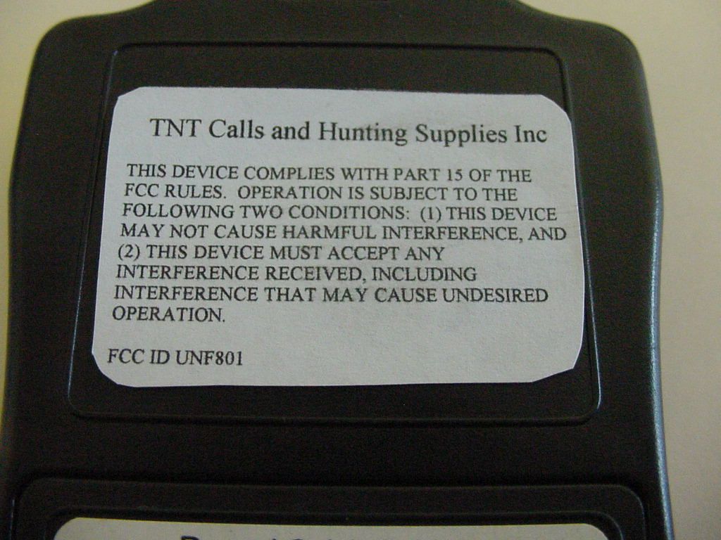
Thank you for the purchase of the TNT Calls & Hunting Supplies Inc, Wireless Remote Game Call system. The only Electronic Game Call you will ever need. Please check your Local and State hunting regulations regarding use of Electronic Game Calls for your region. Read and keep these instructions for reference on operation and support System Features • 125ft Wireless Range ( weather conditions may reduce this range, suspend in air for best reception) • On board Microphone ( record live sounds ) • Wireless Volume Control • 360 degree sound from Weather resistant speaker • Six pre-recorded sounds ( most commonly used sounds ) • Three locations R1, R2, R3 to Re-Record custom Calls or load purchased Calls from www.tntremote.com • Special circuitry to maximize battery life for Base and Remote units. • Weather Resistant Housings • Audio IN and Audio OUT ports. Easily transfer calls to or from the base. • Base easily synchronizes with multiple TNT remotes. Battery Installation 1. Remove Remote battery cover and install (2) AAA batteries. ( fig 1 ) Follow battery installation guide located inside battery compartment. Verify that Light ( fig 2 ) on remote Flashes when any Button is activated. 2. Remove Base battery cover and install (4) AA batteries. ( fig 3 ) Follow battery installation guide located on inside of battery compartment. 3. Contact [email protected] or 1-888-909-HUNT for any warranty or operation assistance. How to Change Channels Channel Setup (Fig 4) 1. Remove Battery cover from Remote and set slide switch to any desired Channel. Up to 8 different systems can be operated in the same area without interference depending on the Channel of the Remote. Base & Remote Synchronize (Fig 5) 2. Press ON/OFF switch located on Label side of Unit, Indicator LED will Flash for ON. 3. On Base Unit, OPEN Control Door located on side of unit. 4. Press/Release Synchronize button ( LED Indicator will start to flash). 5. Press/Release any of the buttons on the Remote (Base LED will stop flashing). 6. Base and Remote are now synchronized. System is ready for use. 7. Repeat the above steps to synchronize any additional TNT remotes to the Base. Play Sounds 1. Press/Release any of the buttons on the remote to play the Pre-Recorded or one of the custom Recordable Game Calls. ( Base must be turned ON) 2. Re-recordable buttons (R1, R2, R3) come with factory statement “ See Instructions for Changing this sound” loaded in these locations. Re-Recordable Locations ( Can re-record many times over ) Example described using R1, Base must be ON. Use same procedure for R2 and R3 1. Press and HOLD R1 until light on remote FLASHES then Release button 2. Base is now in Standby Record Mode – LED indicator flashes on Base 3. Press/Release R1 – Base is now recording. Max Record time is 18 seconds Fig 1 Fig 2 Light Fig 3 Fig 4 Fig 5 ON/OFF LED Indicator 4. Press/Release R1 anytime to stop recording during the 18 seconds or the record will stop automatically after the 18 seconds. 5. Press/Release R1 to play recorded sound. 6. Note: The closer and louder the live sound is to the Base microphone the better the recording. Transfer Purchased Sounds to R1,R2,R3 from Computer to Base 1. Consult your computer user manual on how to play sounds from your audio card. 2. By purchasing from www.tntremote.com an Audio Cable and using the Audio IN port on the Base, follow the same steps outlined in the Record Live section to transfer sounds from your computer. 3. Vary the volume on the computer to get best results. 4. Visit http://www.tntremote.com for more detailed instructions. Save Recorded Sounds from Base to Computer 1. Consult your computer owner’s manual on how to Record files. 2. Sounds which have been saved in any of the Re-Recordable locations R1, R2, R3 may be transferred from the Base and saved on your Computer for later use by using the Audio Out port on the Base. 3. Visit http://www.tntremote.com for more detailed instructions. Basic Care and Handling Do’s and Don’ts *As with any electronic device care must be taken to keep the Electronics from getting wet. DO NOT: submerge base or remote in Water DO NOT: mix old and new batteries DO NOT: expose Base or Remote to excessive Shock DO NOT: puncture speaker DO NOT: operate in rainy conditions without Battery or Control door attached DO: follow State and Local Hunting laws. DO: make sure Base power is turned ON before use. DO: check and make sure to use Fresh Batteries DO: position Base unit above Ground for best reception Warranty This product is warranted for 90 days from date of purchase for workmanship and operation under normal use. All warranty claims must be accompanied with an original sales receipt. Contact [email protected] or 1-888-909- HUNT for all inquiries . Pre-Recorded Pre-Recorded Re-Recordable Indicator Volume UP Volume Down Description of control found on Base Unit DC IN – For home use without batteries. Power supply found at www.tntremote.com . Any other supply may void warranty Audio In – Used to Transfer Calls from Computer to Base Audio Out – Used to Transfer Calls from Base to Computer Synchronize – Used to synchronize new Remotes to Base Unit ON/OFF LED Indicato r Channel Select AAA Batteries G:\Labels\NFF8607 rev 2.doc FCC Statement: This device complies with part 15 of the FCC Rules. Operation is subject to the following two conditions: (1) This device may not cause harmful interference, and (2) this device must accept any interference received, including interference that ma y cause undesired operation. The Manufacturer is not responsible for any Radio or TV interference caused by unauthorized modifications to this equipment. Such modifications could void the user’s authority to operate the equipment.
External Photos
TNT CALLS & HUNTING SUPPLIES, INC. FCC ID: UNF801 EXTERNAL PHOTOS
Internal Photos
TNT CALLS & HUNTING SUPPLIES, INC. FCC ID: UNF801 INTERNAL PHOTOS
Test Report
FCC TEST REPORT PART 15.231 APPLICANT TNT CALLS & HUNTING SUPPLIES, INC. ADDRESS 355 STAR HOPE LANE ELSBERRY MISSOURI 63343 USA FCC ID UNF801 MODEL NUMBER 801 PRODUCT DESCRIPTION WIRELESS REMOTE CONTROL TRANSMITTER DATE SAMPLE RECEIVED 12/4/2006 DATE TESTED 12/13/2006 TESTED BY JOSEPH SCOGLIO APPROVED BY MARIO DE ARANZETA TIMCO REPORT NO. 3301UT6TestReport.doc TEST RESULTS PASS FAIL TOTAL PAGES 15 THE ATTACHED REPORT SHALL NOT BE REPRODUCED EXCEPT IN FULL WITHOUT THE WRITTEN APPROVAL OF TIMCO ENGINEERING, INC. 849 NW STATE ROAD 45 NEWBERRY, FL 32669 USA PH: 888.472.2424 OR 352.472.5500 FAX: 352.472.2030 EMAIL: [email protected] HTTP://WWW.TIMCOENGR.COM APPLICANT: TNT CALLS & HUNTING SUPPLIES, INC. FCC ID: UNF801 REPORT: T\TNT CALLS_UNF\3301UT6\3301UT6TestReport.doc Page 2 of 15 TABLE OF CONTENTS GENERAL INFORMATION......................................................... 3 COMPLIANCE WITH PART 15.231(a)........................................... 4 EMC EQUIPMENT LIST.......................................................... 5 TEST PROCEDURE............................................................ 6 RADIATION INTERFERENCE................................................... 7 CALCULATION OF DUTY CYCLE................................................ 9 OCCUPIED BANDWIDTH....................................................... 14 APPLICANT: TNT CALLS & HUNTING SUPPLIES, INC. FCC ID: UNF801 REPORT: T\TNT CALLS_UNF\3301UT6\3301UT6TestReport.doc Page 3 of 15 GENERAL INFORMATION EUT Specification The test results relate only to the items tested. FCC ID UNF801 Model Number 801 Product Description WIRELESS REMOTE CONTROL TRANSMITTER Operating Frequency 434 MHz Primary Power 110VAC/60HZ EUT Power Secondary Power N/A Prototype Pre-Production Test Item Production Fixed Mobile Type of Equipment Portable Test Standards FCC Part 15, Subpart C, ANSI C63.4-2003 Modifications to DUT None Test exercise The EUT was set in continuous transmit mode of operation. Test Facility Timco Engineering Inc. 849 NW State Road 45 Newberry, FL 32669. Receiver The receiver portion of this system has been tested and meets all of the FCC requirements per FCC rules Part 15.109. A report was issued and a copy of this report is available upon request. APPLICANT: TNT CALLS & HUNTING SUPPLIES, INC. FCC ID: UNF801 REPORT: T\TNT CALLS_UNF\3301UT6\3301UT6TestReport.doc Page 4 of 15 COMPLIANCE WITH PART 15.231(a) Part 15.231(a): • Continuous operation: Yes No • Control signal only: Yes No • Data transmission with a control signal Yes No N/A Description of control signal: _______________(notes: indicate whether such info is included in supporting exhibit such as operation description page xx) Part 15.231(a)(1): • Manually operated device: Yes No • Does it meet the 5s deactivation requirement after the switch is being released: Yes No Description: _______________(notes: a plot showing the pulse train does not necessarily constitute an objective evidence of compliance with the deactivation requirement. A plot should be accompanied by an explanation and/or statement of compliance, if not otherwise clearly stated in supporting documentation e.g. operation description page xx) Part 15.231(a)(2): • Automatically operated device: Yes No • Does it meet the 5s deactivation requirement after being activated: Yes No Description: _______________(notes: a plot showing the pulse train does not necessarily constitute an objective evidence of compliance with the deactivation requirement. A plot should be accompanied by an explanation and/or statement of compliance, if not otherwise clearly stated in supporting documentation e.g. operation description page xx) Part 15.231(a)(3): • Periodic transmission at regular predetermined intervals: Yes No N/A Description: ________________ • Polling or supervision transmissions, including data, to check system integrity check requires a total transmission time not exceeding 2s per hour: Yes No N/A Part 15.231(a)(4): Operation involving fire, security, or safety of life, when activated to signal an alarm, may operate during the pendency of the alarm condition. Does the transmitter meet the condition? Yes No N/A APPLICANT: TNT CALLS & HUNTING SUPPLIES, INC. FCC ID: UNF801 REPORT: T\TNT CALLS_UNF\3301UT6\3301UT6TestReport.doc Page 5 of 15 EMC EQUIPMENT LIST Device Manufacturer Model Serial Number Cal/Char Date Due Date 3-Meter OATS TEI N/A N/A Listed 1/11/06 1/10/09 3/10-Meter OATS TEI N/A N/A Listed 3/27/04 3/26/07 Analyzer Tan Tower Spectrum Analyzer HP 8566B Opt 462 3138A07786 3144A20661 CAL 12/7/05 12/7/07 Analyzer Tan Tower RF Preselector HP 85685A 3221A01400 CAL 12/7/05 12/7/07 Analyzer Tan Tower Quasi- Peak Adapter HP 85650A 3303A01690 CAL 12/8/05 12/8/07 Analyzer Tan Tower Preamplifier HP 8449B-H02 3008A00372 CAL 12/8/05 12/8/07 Analyzer Blue Tower Spectrum Analyzer HP 8568B 2928A04729 2848A18049 CAL 4/13/05 4/13/07 Analyzer Blue Tower RF Preselector HP 85685A 2926A00983 CAL 9/5/05 9/5/07 Analyzer Blue Tower Quasi- Peak Adapter HP 85650A 2811A01279 CAL 4/13/05 4/13/07 Analyzer Silver Tower Spectrum Analyzer HP 8566B Opt 462 3552A22064 3638A08608 CAL 10/30/06 10/30/08 Analyzer Silver Tower RF Preselector HP 85685A 2620A00294 CAL 10/30/06 10/30/08 Analyzer Silver Tower Quasi- Peak Adapter HP 85650A 3303A01844 CAL 10/30/06 10/30/08 Analyzer Open- Frame Tower Preamplifier HP 8449B 3008A01075 CAL 8/8/05 8/8/07 Antenna: Biconnical Electro-Metrics BIA-25 1171 CAL 4/29/05 4/29/07 Antenna: Biconnical Eaton 94455-1 1096 CAL 10/11/06 10/11/08 Antenna: Biconnical Eaton 94455-1 1057 CAL 12/12/05 12/12/07 APPLICANT: TNT CALLS & HUNTING SUPPLIES, INC. FCC ID: UNF801 REPORT: T\TNT CALLS_UNF\3301UT6\3301UT6TestReport.doc Page 6 of 15 TEST PROCEDURE RADIATION INTERFERENCE: The test procedure used was ANSI standard C63.4-2003 using a spectrum analyzer with a preselector. The bandwidth of the spectrum analyzer was 100 kHz with an appropriate sweep speed. The analyzer was calibrated in dB above a microvolt at the output of the a…
Text truncated - open the document above for the full version.
Test Setup Photos
Thank you for the purchase of the TNT Calls & Hunting Supplies Inc, Wireless Remote Game Call system. The only Electronic Game Call you will ever need. Please check your Local and State hunting regulations regarding use of Electronic Game Calls for your region. Read and keep these instructions for reference on operation and support System Features • 125ft Wireless Range ( weather conditions may reduce this range, suspend in air for best reception) • On board Microphone ( record live sounds ) • Wireless Volume Control • 360 degree sound from Weather resistant speaker • Six pre-recorded sounds ( most commonly used sounds ) • Three locations R1, R2, R3 to Re-Record custom Calls or load purchased Calls from www.tntremote.com • Special circuitry to maximize battery life for Base and Remote units. • Weather Resistant Housings • Audio IN and Audio OUT ports. Easily transfer calls to or from the base. • Base easily synchronizes with multiple TNT remotes. Battery Installation 1. Remove Remote battery cover and install (2) AAA batteries. ( fig 1 ) Follow battery installation guide located inside battery compartment. Verify that Light ( fig 2 ) on remote Flashes when any Button is activated. 2. Remove Base battery cover and install (4) AA batteries. ( fig 3 ) Follow battery installation guide located on inside of battery compartment. 3. Contact [email protected] or 1-888-909-HUNT for any warranty or operation assistance. How to Change Channels Channel Setup (Fig 4) 1. Remove Battery cover from Remote and set slide switch to any desired Channel. Up to 8 different systems can be operated in the same area without interference depending on the Channel of the Remote. Base & Remote Synchronize (Fig 5) 2. Press ON/OFF switch located on Label side of Unit, Indicator LED will Flash for ON. 3. On Base Unit, OPEN Control Door located on side of unit. 4. Press/Release Synchronize button ( LED Indicator will start to flash). 5. Press/Release any of the buttons on the Remote (Base LED will stop flashing). 6. Base and Remote are now synchronized. System is ready for use. 7. Repeat the above steps to synchronize any additional TNT remotes to the Base. Play Sounds 1. Press/Release any of the buttons on the remote to play the Pre-Recorded or one of the custom Recordable Game Calls. ( Base must be turned ON) 2. Re-recordable buttons (R1, R2, R3) come with factory statement “ See Instructions for Changing this sound” loaded in these locations. Re-Recordable Locations ( Can re-record many times over ) Example described using R1, Base must be ON. Use same procedure for R2 and R3 1. Press and HOLD R1 until light on remote FLASHES then Release button 2. Base is now in Standby Record Mode – LED indicator flashes on Base 3. Press/Release R1 – Base is now recording. Max Record time is 18 seconds Fig 1 Fig 2 Light Fig 3 Fig 4 Fig 5 ON/OFF LED Indicator 4. Press/Release R1 anytime to stop recording during the 18 seconds or the record will stop automatically after the 18 seconds. 5. Press/Release R1 to play recorded sound. 6. Note: The closer and louder the live sound is to the Base microphone the better the recording. Transfer Purchased Sounds to R1,R2,R3 from Computer to Base 1. Consult your computer user manual on how to play sounds from your audio card. 2. By purchasing from www.tntremote.com an Audio Cable and using the Audio IN port on the Base, follow the same steps outlined in the Record Live section to transfer sounds from your computer. 3. Vary the volume on the computer to get best results. 4. Visit http://www.tntremote.com for more detailed instructions. Save Recorded Sounds from Base to Computer 1. Consult your computer owner’s manual on how to Record files. 2. Sounds which have been saved in any of the Re-Recordable locations R1, R2, R3 may be transferred from the Base and saved on your Computer for later use by using the Audio Out port on the Base. 3. Visit http://www.tntremote.com for more detailed instructions. Basic Care and Handling Do’s and Don’ts *As with any electronic device care must be taken to keep the Electronics from getting wet. DO NOT: submerge base or remote in Water DO NOT: mix old and new batteries DO NOT: expose Base or Remote to excessive Shock DO NOT: puncture speaker DO NOT: operate in rainy conditions without Battery or Control door attached DO: follow State and Local Hunting laws. DO: make sure Base power is turned ON before use. DO: check and make sure to use Fresh Batteries DO: position Base unit above Ground for best reception Warranty This product is warranted for 90 days from date of purchase for workmanship and operation under normal use. All warranty claims must be accompanied with an original sales receipt. Contact [email protected] or 1-888-909- HUNT for all inquiries . Pre-Recorded Pre-Recorded Re-Recordable Indicator Volume UP Volume Down Description of control found on Base Unit DC IN – For home use without batteries. Power supply found at www.tntremote.com . Any other supply may void warranty Audio In – Used to Transfer Calls from Computer to Base Audio Out – Used to Transfer Calls from Base to Computer Synchronize – Used to synchronize new Remotes to Base Unit ON/OFF LED Indicato r Channel Select AAA Batteries G:\Labels\NFF8607 rev 2.doc FCC Statement: This device complies with part 15 of the FCC Rules. Operation is subject to the following two conditions: (1) This device may not cause harmful interference, and (2) this device must accept any interference received, including interference that ma y cause undesired operation. The Manufacturer is not responsible for any Radio or TV interference caused by unauthorized modifications to this equipment. Such modifications could void the user’s authority to operate the equipment.
Contact Information
Applicant
David Linhoff
Test Firm
Timco Engineering, Inc.Sid Sanders
Technical Specifications
| # | Rule Parts | Frequency Range | Power Output |
|---|---|---|---|
| 1 | 15.231 | 433.62 MHz - 434.22 MHz | - |