UO20906Medical Wetness Detector
Fresenius Medical Care - NA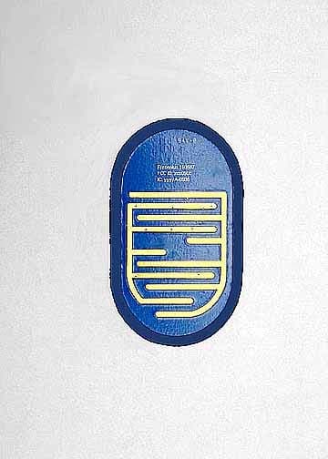
Click to zoom
Application Details
- Equipment Class
- DSC - Part 15 Security/Remote Control Transmitter
- Date of Grant
- Nov 12, 2006
- Application Purpose
- Original Equipment
- Date of Application
- Oct 31, 2006
- Equipment Note
- Medical Wetness Detector
- Frequency Range
- 433.91500000 - 433.91500000
- Company
- Fresenius Medical Care - NA
- Country
- United States
Documents & Files
Document Text
Text extracted from the exhibit documents filed with the FCC. Open a document above to read the original.
Users Manual
2008K Operator’s Manual P/N 507938 Rev. 1 Draft 2 Page 1 of 6 Fresenius USA 2008K Hemodialysis Machine Operator’s Guide Wireless Wetness Detector Addendum Page 2 of 6 P/N 507938 Rev. 1 Draft 2 2008K Operator’s Manual Wireless Wetness Detector for Patients The Wireless Wetness Detector is a disposable device that monitors for leaks. It transmits radio signals to the 2008K hemodialysis machine and alerts the machine when the detector senses a conductive substance like fluid on its sensors. When the Wireless Wetness Detector option has been set, a gray Drop icon will be displayed in the Dialogue Box. The detector is not activated until the icon is green. Patient Wireless Wetness Detector Setup During Treatment Proceed with typical treatment setup (as explained in Chapter 2 of the 2008K Hemodialysis Machine Operator’s Manual P/N 490042), following clinic instructions. Use these instructions before starting the Tx Clock to activate the Wireless Wetness Detector. 1. After preparing the patient’s access, create a wetness signal within 10 feet of the machine by touching the metal pattern on the bottom of the detector for at least 3 seconds (see Figure 1) with a conductive surface. Fresenius Medical Care recommends using gauze damp with disinfectant to activate it. Warning! Keep access sites uncovered and monitored. Machine alarms do not sound in every blood loss situation. Warning! Do not touch non-sterile objects to the Wireless Wetness Detector sensor. Figure 1 – Create Wetness Signal Deleted: a rag D eleted: 2008K Operator’s Manual P/N 507938 Rev. 1 Draft 2 Page 3 of 6 2. The Wireless Wetness Detector will send a wetness signal to the machine. Make sure that an audible alarm sounds and the Status Bar turns red and displays the message “Wetness Detected #1” (see Figure 2). Figure 2 – Home screen: Wetness Detected #1 3. Press the 1 key to learn the Wireless Wetness Detector and clear the alarm. The Drop icon in the Dialogue Box will turn green. 4. Place the detector on the access site bandage and secure it in place with another bandage. The Wireless Wetness Detector will continue to transmit signals to the dialysis machine for the next eight hours. Warning! Place the detector below the access site on top of no more than two layers of gauze. Failure to do so may allow a blood leak to go undetected. Undetected blood leaks can cause serious injury or death. 5. Touch the Tx Paused button and press the CONFIRM key. The treatment will begin counting down. If a “Wetness Detected” alarm occurs, it can be cleared with the RESET key. Note: If the machine displays the message “Wetness Detector Not Active”, the Wireless Wetness Detector must be re-activated by touching the metal pattern on the bottom of the detector again. Note: If a “Wetness Detected” alarm occurs three times within 10 minutes, the Dialogue Box will display the following message: “Press 0 to disable Wetness” If the 0 key is then pressed, its audible alarm will be deactivated. The Drop icon Page 4 of 6 P/N 507938 Rev. 1 Draft 2 2008K Operator’s Manual in the Dialogue Box will be yellow to show that a Wireless Wetness Detector is disabled. Note: If the machine displays the message “Wet Low Battery #X”, where the “X” indicates the Wireless Wetness Detector number, that Wireless Wetness Detector must be replaced. Note: Pressing the New Tx key and selecting a new treatment, changing the Blood Sensed status, or running a rinse program will clear Wireless Wetness Detector #1’s association with the machine. If any of those occur, Wireless Wetness Detector #1 must be relearned as explained above. Using additional Wireless Wetness Detectors Up to three Wireless Wetness Detectors may be linked to one machine. Wireless Wetness Detectors #2 and #3 must be set in Service Mode and are not patient- specific. Setting Wireless Wetness Detector Option in Service Mode The “Wireless Wetness” option must be selected in Service Mode in order to use any Wireless Wetness Detectors. Set the Wireless Wetness toggle-button, located in the “Module Options” tab of the “Hardware Options” tab, to Yes. Figure 4 – Service Mode: Options: Module Options screen 2008K Operator’s Manual P/N 507938 Rev. 1 Draft 2 Page 5 of 6 Learning Wireless Wetness Detectors #2 and #3 ID’s Wireless Wetness Detectors 2 and 3 are learned only in Service Mode. They are machine specific and do not need to be relearned with every new treatment. To set Wireless Wetness Detectors, go to the “Module Options” screen in Service Mode. Next touch the Wetness Detector X toggle-button (where X= 2 or 3) to set it from CLEAR to LEARN, and then press the CONFIRM key. When directed by the Status Bar, touch the metal pattern on the bottom of the detector and then release it when indicated. The device’s learned ID will appear in the ID box below the button. You may set the other detector by touching its corresponding button and activating it as described above. Clearing Wireless Wetness Detectors #2 and #3 ID’s To clear a detector’s association with the machine, touch that detector’s Wireless Detector toggle-button to set it from LEARN to CLEAR, and then press the CONFIRM key. The ID box will display “0” and the selected Wireless Wetness Detector will no longer be linked to the machine. When Wireless Wetness Detectors 2 and 3 sense wetness during treatment, they act like Wireless Wetness Detector #1 and may be reset using the RESET key. Similarly, if the 0 key is pressed during a detector’s third alarm, it will disable the alarming device. That Wireless Wetness Detector must then be relearned in Service Mode. Wireless Wetness Detector Care Wireless Wetness Detectors in contact with patients or fluids should be cleaned after every treatment. They can be cleaned with very dilute bleach or other suitable hospital disinfectant. Freshly prepared dilute bleach solution (1:100) is currently recommended by the Center for Disease Control as a suitable disinfectant for the Hepatitis virus. Because surface contamination is…
Text truncated - open the document above for the full version.
Users Manual
2008K@home Wireless Wetness Detector User’s Guide 2 P/N 507939 Rev 4 Draft 2008K@home User’s Guide Activating the Wireless Wetness Detector 1 Touch Detector D e l eted : 2008K@home User’s Guide P/N 507939 Rev 4 Draft 3 Wireless Wetness Detector The Wireless Wetness Detector is a disposable device that can sense leaks. It transmits radio signals to your 2008K@home hemodialysis machine and alerts your machine when fluid is on the detector’s sensors. Note : If your machine is used in a clinic, have a qualified technician set the “In-Center” option in Service Mode. Use the 2008K Hemodialysis Machine Operator’s Guide Wireless Wetness Detector Addendum (P/N 507938) as a guide. When the Wireless Wetness Detector option has been set, a gray Drop icon will be displayed in the Dialogue Box. The detector is not activated until the icon is green. Wireless Wetness Detector Setup During Treatment Follow your clinic’s instructions, using Book 2: Treatment Walkthrough (P/N 490080) as a guide. Use these instructions before starting the Tx Clock to activate the Wireless Wetness Detector. The Dialogue Box will display a message telling you to touch your detector. 1 Touch detector After preparing the access site, create a wetness signal within 10 feet of your machine by touching the metal pattern on the bottom of the detector for at least three seconds. Fresenius Medical Care recommends using gauze damp with disinfectant to activate it. Warning : Keep access sites uncovered and monitored. Machine alarms do not sound in every blood loss situation. Warning : Do not touch non-sterile objects to the Wireless Wetness Detector sensor. Deleted: a rag 4 P/N 507939 Rev 4 Draft 2008K@home User’s Guide Activating the Wireless Wetness Detector 1 Check Alarm 2 Press RESET 3 Place Detector 2008K@home User’s Guide P/N 507939 Rev 4 Draft 9 user’s authority to operate the equipment. Formatted: Font: 4 pt Deleted: ¶ 8 P/N 507939 Rev 4 Draft 2008K@home User’s Guide Appendix Setting the Wireless Wetness option You must have your clinic set the “Wireless Wetness” option in Service Mode before you can use the Wireless Wetness Detector. General Warnings This device complies with Part 15 of the FCC Rules. Operation is subject to the following two conditions: (1) this device may not cause harmful interference, and (2) this device must accept any interference received, including interference that may cause undesired operation. This equipment has been tested and found to comply with the limits for a Class B digital device, pursuant to Part 15 of the FCC Rules. These limits are designed to provide reasonable protection against harmful interference in a residential installation. This equipment generates, uses and can radiate radio frequency energy and, if not installed and used in accordance with the instructions, may cause harmful interference to radio communications. However, there is no guarantee that interference will not occur in a particular installation. If this equipment does cause harmful interference to radio or television reception, which can be determined by turning the equipment off and on, the user is encouraged to try to correct the interference by one or more of the following measures: • Reorient or relocate the receiving antenna. • Increase the separation between the equipment and receiver. • Connect the equipment into an outlet on a circuit different from that to which the receiver is connected. • Consult the dealer or an experienced radio/TV technician for help. Caution : Changing or modifying the Wireless Wetness Detector without the expressed written consent of Fresenius Medical Care could void the Formatted: Font: 10 pt Formatted: Indent: Left: 0" Formatted: Font: Arial, Bold Formatted: Font: 11 pt Formatted: Font: 10 pt Formatted: Font: 11 pt Formatted: Indent: Left: 1" Formatted: Bullets and Numbering Formatted: Bullets and Numbering Formatted: Font: 4 pt Formatted: Font: 4 pt Formatted: No bullets or numbering Formatted TableDeleted: ¶ ¶¶Wireless Wetness Detector Care¶The Wireless Wetness Detector should be cleaned after every treatment. It can be cleaned with very dilute bleach or other suitable hospital disinfectant. Freshly prepared dilute bleach solution (1:100) is currently recommended by the Center for Disease Control as a suitable disinfectant for the Hepatitis virus. Because surface contamination is the general mode of transmission for this type of virus, thorough cleaning of the Wireless Wetness Detector is essential.¶¶¶ 2008K@home User’s Guide P/N 507939 Rev 4 Draft 5 1 Check for alarm The Wireless Wetness Detector will send a wetness signal to your machine. Make sure that an audible alarm sounds and the Status Bar turns red and displays the message “ Wetness Detected ”. The Drop icon in the Dialogue Box will turn red to indicate wetness sensed. 2 Press RESET Press the RESET key to clear the alarm. The drop icon in the Dialogue Box will turn green, indicating that the Wireless Wetness Detector is activated (see next page). Note : If the same “Wetness Detected” alarm is reset three times within 10 minutes, the Dialogue Box will display the message “Press 0 to disable Wetness Detector.” If you then press the 0 key, the audible alarm will be deactivated for the remainder of your treatment. The Drop icon in the Dialogue box will be yellow to show the detector is deactivated. Note : If your machine displays the message “Wetness Low Battery”, the Wireless Wetness Detector must be replaced before your next treatment. 3 Place detector Place the detector on the access site bandage and secure it in place with another bandage. Warning : Place the detector below the access site on top of no more than two layers of gauze. Failure to do so may allow a blood leak to go undetected. Undetected blood leaks can cause serious injury or death. 6 P/N 507939 Rev 4 Draft 2008K@home User’s Guide Start Treatment 1 1 2008K@home User’s Guide P/N 507939 Rev 4 Draft 7 1 Start treatment Touch the Tx Paused button and press the CONF…
Text truncated - open the document above for the full version.
Cover Letter(s)
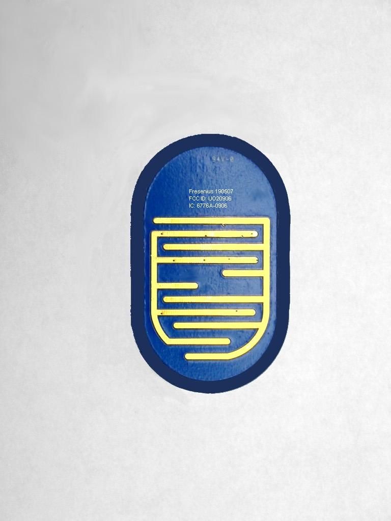
Explanation of model number differences: The 190427 model is a board assembly with exposed electronic components on one side - this is what CKC tested. It has silkscreen on the component side with the 190427 model number, but no FCC or IC ID-code text. The 190507 model is the 190427 with a plastic encapsulant covering the components and the silk-screened 190427 model number. The bottom side is left exposed, and is where the silk-screen is located listing 190507 model number and the two ID-codes. The two models are electrically identical. Fresenius will only market the 190507 model.
External Photos
Front Top Bottom with Label Side
Internal Photos
Internal Front Internal Back End Side
Test Report
Page 1 of 34 Report No.: FC06-053 FRESENIUS MEDICAL CARE - NA TEST REPORT FOR THE MEDICAL WETNESS DETECTOR, 190427 FCC PART 15.231 & 15.209 AND RSS-210 COMPLIANCE DATE OF ISSUE: OCTOBER 2, 2006 PREPARED FOR: Fresenius Medical Care - NA 2637 Shadelands Drive Walnut Creek, CA 94598 PREPARED BY: Mary Ellen Clayton CKC Laboratories, Inc. 5046 Sierra Pines Drive Mariposa, CA 95338 P.O. No.: 4503290777 W.O. No.: 85642 Date of test: September 20-29, 2006 Report No.: FC06-053 This report contains a total of 34 pages and may be reproduced in full only. Partial reproduction may only be done with the written consent of CKC Laboratories, Inc. The results in this report apply only to the items tested, as identified herein. Page 2 of 34 Report No.: FC06-053 TABLE OF CONTENTS Administrative Information .............................................................................................3 FCC to Canada Standard Correlation Matrix...................................................................4 Conditions for Compliance ..............................................................................................4 Approvals .........................................................................................................................4 FCC 15.31(e) Voltage Variation......................................................................................5 FCC 15.31(m) Number Of Channels ...............................................................................5 FCC 15.33(a) Frequency Ranges Tested .........................................................................5 FCC 15.35 Analyzer Bandwidth Settings ........................................................................5 FCC 15.203 Antenna Requirements ................................................................................5 EUT Operating Frequency ...............................................................................................5 Temperature And Humidity During Testing....................................................................5 Equipment Under Test (EUT) Description ......................................................................6 Equipment Under Test .....................................................................................................6 Peripheral Devices ...........................................................................................................6 Report of Measurements ..................................................................................................7 Table 1: FCC 15.231 Carrier Emission Levels ....................................................7 Table 2: FCC 15.231/15.209 Six Highest Spurious Emission Levels .................8 FCC 15.231(c) Occupied Bandwidth Plot ...........................................................9 Pulse Timing ........................................................................................................10 EUT Setup........................................................................................................................23 Correction Factors............................................................................................................23 Table A: Sample Calculations .............................................................................23 Test Instrumentation and Analyzer Settings ....................................................................24 Spectrum Analyzer Detector Functions ...............................................................24 Peak..........................................................................................................24 Quasi-Peak ...............................................................................................24 Average ....................................................................................................24 EUT Testing.....................................................................................................................25 Radiated Emissions ..............................................................................................25 Appendix A: Test Setup Photographs..............................................................................26 Photograph Showing Radiated Emissions ...........................................................27 Photograph Showing Radiated Emissions ...........................................................28 Photograph Showing Radiated Emissions ...........................................................29 Appendix B: Test Equipment List ...................................................................................30 Appendix C: Measurement Data Sheets ..........................................................................31 Page 3 of 34 Report No.: FC06-053 ADMINISTRATIVE INFORMATION DATE OF TEST: September 20-29, 2006 DATE OF RECEIPT: September 20, 2006 MANUFACTURER: Fresenius Medical Care - NA 2637 Shadelands Drive Walnut Creek, CA 94598 REPRESENTATIVE: Mike Owen TEST LOCATION: CKC Laboratories, Inc. 5046 Sierra Pines Drive Mariposa, CA 95338 TEST METHOD: ANSI C63.4 (2003), RSS-210 and RSS GEN PURPOSE OF TEST: To demonstrate the compliance of the Medical Wetness Detector, 190427 with the requirements for FCC Part 15.231/15.209 and RSS-210 devices. Page 4 of 34 Report No.: FC06-053 FCC TO CANADA STANDARD CORRELATION MATRIX Canadian Standard Canadian Section FCC Standard FCC SectionTest Description RSS GEN7.1.447CFR15.203Antenna Connector Requirements RSS GEN7.2.147CFR15.35(c)Pulsed Operation RSS GEN7.2.247CFR15.207AC Mains Conducted Emissions Requirement RSS 210A1.1.147CFR15.231(a)General Requirements for Momentary Equipment RSS 210A1.1.247CFR15.231(b)Field Strength Requirements RSS 210A1.1.347CFR15.231(c)Bandwidth Requirements RSS 210A1.1.447CFR15.231(d) Frequency Stability for 40.66 - 40.70 MHz equipment RSS 210A1.1.547CFR15.231(e)Reduced Field Strength Requirements IC 3082A-1784962Site File No. CONDITIONS FOR COMPLIANCE No modifications to…
Text truncated - open the document above for the full version.
Test Setup Photos
PHOTOGRAPH SHOWING RADIATED EMISSIONS Radiated Emissions - X Orientation PHOTOGRAPH SHOWING RADIATED EMISSIONS Radiated Emissions - Y Orientation PHOTOGRAPH SHOWING RADIATED EMISSIONS Radiated Emissions - Z Orientation
Contact Information
Applicant
Gregg Fuhriman(Sr. Design Engineer)
Technical Contact
CKC Laboratories, Inc.Mary Ellen Clayton
[email protected]800-500-4362
5046 Sierra Pines Drive · Mariposa, California · United States
Non-Technical Contact
CKC Laboratories, Inc.Mary Ellen Clayton
[email protected]800-500-4362
Test Firm
CKC Laboratories, Inc.Steve Behm
Technical Specifications
| # | Rule Parts | Frequency Range | Power Output |
|---|---|---|---|
| 1 | 15.231 | 433.915 MHz - 433.915 MHz | - |