UOGWKLK001Secure Entry Access Transmitter
FP Wireless LLC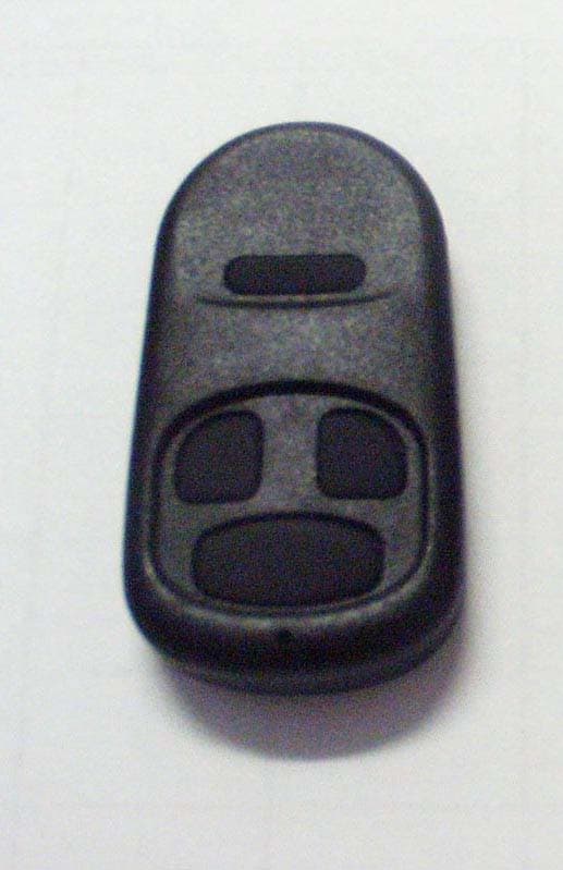
Click to zoom
Application Details
- Equipment Class
- DSC - Part 15 Security/Remote Control Transmitter
- Date of Grant
- Jan 17, 2007
- Application Purpose
- Original Equipment
- Date of Application
- Jan 17, 2007
- Equipment Note
- Secure Entry Access Transmitter
- Frequency Range
- 433.92000000 - 433.92000000
- Company
- FP Wireless LLC
- Country
- United States
Documents & Files
Document Text
Text extracted from the exhibit documents filed with the FCC. Open a document above to read the original.
Users Manual
Remote Features The FP AE-1 Wireless Remote unit can be ordered with your custom ID code and Facility Code. It utilizes a secure code structure that cannot be captured and replayed to grant access. The AE-1 also has a battery that is easily replaceable by the user. Receiver Features The FP AE-2 Wireless Receiver is Wiegand output, compatible with all industry standard devices. It is two channel – has two separate outputs to control entry to 2 different entrances from the single receiver. There are no dip switches for setting codes, etc., only a single switch to assign AE-1 Remote buttons to the appropriate output. The AE-2 has a built in antenna suitable for most installations. There are provisions for an external antenna if the installation environment requires this. There is also a sensitivity control to assist in desired operation. It is mounted in a weather resistant housing, operates from 12 volts DC and has a pluggable connector for ease of installation. Receiver Cable Requirements The AE-2 receiver operates at up to the Wiegand standard of 500 ft of cable, using seven conductor, shielded, stranded cable. Per the Security Industry Association’s Wiegand specification, AWG 24 (such as Belden 9537) is the minimum gauge required for data transfer in a 500 foot run. However, the proper wire gauge to use must be determined by the current draw requirements of the receiver, length of cable run, and the voltage applied to the receiver. Shield (drain) continuity must run from the receiver to the access panel. Shield and receiver ground must be tied together at the access panel and connected to an earth ground at one point. Receiver Mounting The receiver should be mounted in an area that is relatively free of large metal obstructions such as ductwork, appliances, wire lath, etc. The base of the enclosure can be loosely mounted on the wall as other installation steps and wiring are completed. The unit must then be removed from the wall to secure the cover, after which it may be permanently mounted. Main Terminal Block The main terminal block is used to connect DC power and receiver output connections. In outdoor installations, a weatherproofing compound should be used to seal the cable entry. Connect cable according to installation instructions. Receiver Range AE-2 Receiver range may be extended or reduced depending on the needs of the installation. As shipped, the open air range between remote and receiver is approximately 150 feet. This range may be reduced to a minimum of several feet by adjusting the range adjustment control in the negative (counter-clockwise) direction. For longer range, an external monopole antenna may be installed at the external antenna connector. Using this antenna, open air range out to 300 feet may be obtained. A coaxial cable may be used to remote an antenna if desired. In outdoor installations, a weatherproofing compound should be used to seal the cable/antenna entry. LED Indicators The AE-2 Receiver is equipped with Power and Read indication LED’s. See installation manual for complete operating instructions. Remote and Receiver Statements This device complies with Part 15 of the FCC Rules. Operation is subject to the following two conditions: (1) this device may not cause harmful interference, and (2) this device must accept any interference received, including interference that may cause undesired operation. FCC Notice The user is cautioned that equipment modifications not expressly approved by FP Wireless LLC may void the user’s authority to operate the equipment. EXTENDED RANGE WIRELESS WIEGAND OUTPUT SYSTEM - - - - - - AE-1 REMOTE AE-2 RECEIVER USER MANUAL FP WIRELESS, LLC
Cover Letter(s)
tel: 650-726-1263 fax: 650-726-1252 [email protected] Thomas N. Cokenias EMC &Radio Approvals Test & Consulting Services for Commercial, Military, International Compliance P.O. Box 1086 El Granada, CA 94018 email: [email protected] Compliance Certification Services January 18, 2007 561 F Monterey Road Morgan Hill CA 95037 Attention: Mike Kuo Re: Request for confidentiality per 0.457 of FCC Rules Applicant: FP Wireless LLC. FCC ID: UOGWKLK001 Dear Mike, On behalf of my client FP Wireless LLC., I request the following documents associated with this application for certification be withheld from public view: Schematics Block diagrams Operational description FP Wireless LLC. has expended considerable time and funds in developing the referenced product, and disclosure of these documents to competitors would afford them an unfair advantage in developing similar competing products. If you have questions or need further information please don’t hesitate to contact me. Sincerely, T.N. Cokenias Agent for FP Wireless LLC.
External Photos
PRODUCT PHOTOGRAPHS – EXTERNAL VIEWS FP Wireless FCC ID: UOGWKLK001
ID Label/Location Info
LABEL AND LABEL PLACEMENT FP Wireless FCC ID: UOGWKLK001 FCC ID: UOGWKLK001 This device complies with Part 15 of the FCC Rules. Operation is subject to the following two conditions: (1) This device may not cause harmful interference, and (2) This device must accept any interference received, including interference than may cause undesired operation
Internal Photos
PRODUCT PHOTOGRAPHS – INTERNAL VIEWS FP Wireless FCC ID: UOGWKLK001
Test Report
FP Wireless FCC ID: UOGWKLK001 Report No. 07PR002FCC Rev 1.2 15 January 2007 page1 Test Report for Unlicensed Low Power Transmitter FCC Applicable Rule Parts: 15.205, 15.231 Applicant: FP Wireless LLC 105 Serra Way, PMB#356 Milpitas, CA 95035 FCC ID: UOGWKLK001 Test date(s): 12,18 September 2006 Testing performed by: Compliance Certification Services 561F Monterey Road Morgan Hill CA 95037 Description of device: The FP Wireless “Clicker” is a low power transmitter operating at 433.92 MHz, and will be used as part of a secure wireless gate or building entry system. TEST REQUIREMENTS The referenced device is subject to certification under Part 2 of FCC Rules. The specific emissions limits and test requirements are found in Part 15 of FCC Rules. In addition to the device specific requirements listed in 15.231 (re-printed below), the following Part 15 requirements are universal to all unlicensed transmitters and would also apply: 15.19 Labeling requirements 15.20 Accessories 15.21 Information to user 15.31 Measurement standards 15.33 Frequency range of measurements 15.35 Measurement detector functions and bandwidths 15.203 Antenna requirement 15.204 External radio frequency power amplifiers and antenna modifications. 15.205 Restricted bands of operation. 15.209 Radiated emission limits, general requirements. 15.231 Periodic operation in the band 40.66 - 40.70 MHz and above 70 MHz. MEASURMENT PROCEDURES All testing was performed in accordance with ANSI C63.4:2003, using methodologies and instrumentation described therein. FP Wireless FCC ID: UOGWKLK001 Report No. 07PR002FCC Rev 1.2 15 January 2007 page2 REVISION INFORMATION AND ATTESTATION OF RESULTS Report No: 07PR002FCC REV No. Description Revised By: Date - Original Issue T. Cokenias 01/07/2007 1.1 Expand test procedure T. Cokenias 01/09/2007 Add missing cal data Additional setup photo 1.2 Add ANSI C63.4 reference T. Cokenias 01/15/2007 FCC ID: UOGWKLK001meets all FCC requirements for a device of this type. THOMAS N. COKENIAS 15 January 2007 EMC and Radio Regulatory Consultant Agent for FP Wireless LLC. FP Wireless FCC ID: UOGWKLK001 Report No. 07PR002FCC Rev 1.2 15 January 2007 page3 15.205 Restricted bands of operation. Only spurious emissions are permitted in any of the frequency bands listed below: The field strength of emissions appearing within these frequency bands shall not exceed the limits shown in Section 15.209. MHz MHz MHz GHz 0.090 - 0.110 10.495 - 0.505 2.1735 - 2.1905 4.125 - 4.128 4.17725 - 4.17775 4.20725 - 4.20775 6.215 - 6.218 6.26775 - 6.26825 6.31175 - 6.31225 8.291 - 8.294 8.362 - 8.366 8.37625 - 8.38675 8.41425 - 8.41475 12.29 - 12.293 12.51975 - 12.52025 12.57675 - 12.57725 13.36 - 13.41 16.42 - 16.423 16.69475 - 16.69525 16.80425 - 16.80475 25.5 - 25.67 37.5 - 38.25 73 - 74.6 74.8 - 75.2 108 - 121.94 123 - 138 149.9 - 150.05 156.52475 - 156.52525 156.7 - 156.9 162.0125 - 167.17 167.72 - 173.2 240 - 285 322 - 335.4 399.9 - 410 608 - 614 960 - 1240 1300 - 1427 1435 - 1626.5 1645.5 - 1646.5 1660 - 1710 1718.8 - 1722.2 2200 - 2300 2310 - 2390 2483.5 - 2500 2655 - 2900 3260 - 3267 3332 - 3339 3345.8 - 3358 3600 - 4400 4.5 - 5.15 5.35 - 5.46 7.25 - 7.75 8.025 - 8.5 9.0 - 9.2 9.3 - 9.5 10.6 - 12.7 13.25 - 13.4 14.47 - 14.5 15.35 - 16.2 17.7 - 21.4 22.01 - 23.12 23.6 - 24.0 31.2 - 31.8 36.43 - 36.5 15.209 Radiated emission limits, general requirements. Except as provided elsewhere in this paragraph the emissions from an intentional radiator shall not exceed the field strength levels specified in the following table: Frequency (MHz) Field Strength uV/m Measurement distance, m 0.009 - 0.490 0.490 - 1.705 1.705 - 30.0 30 - 88 88 - 216 216 - 960 Above 960 2400/F(kHz) 24000/F (kHz) 30 100 ** 150 ** 200 ** 500 300 30 30 3 3 3 3 ** Except as provided in paragraph (g), fundamental emissions from intentional radiators operating under this Section shall not be located in the frequency bands 54-72 MHz, 76-88 MHz, 174-216 MHz or 470-806 MHz. FP Wireless FCC ID: UOGWKLK001 Report No. 07PR002FCC Rev 1.2 15 January 2007 page4 15.231 Periodic operation in the band 40.66 - 40.70 MHz and above 70 MHz. (a) The provisions of this Section are restricted to periodic operation within the band 40.66 - 40.70 MHz and above 70 MHz. Except as shown in paragraph (e) of this Section, the intentional radiator is restricted to the transmission of a control signal such as those used with alarm systems, door openers, remote switches, etc. Continuous transmissions, voice, video and the radio control of toys are not permitted. Data is permitted to be sent with a control signal. The following conditions shall be met to comply with the provisions for this periodic operation: (1) A manually operated transmitter shall employ a switch that will automatically deactivate the transmitter within not more than 5 seconds of being released. (2) A transmitter activated automatically shall cease transmission within 5 seconds after activation. (3) Periodic transmissions at regular predetermined intervals are not permitted. However, polling or supervision transmissions, including data, to determine system integrity of transmitters used in security or safety applications are allowed if the total duration of transmissions does not exceed more than two seconds per hour for each transmitter. There is no limit on the number of individual transmissions, provided the total transmission time does not exceed two seconds per hour. (4) Intentional radiators which are employed for radio control purposes during emergencies involving fire, security, and safety of life, when activated to signal an alarm, may operate during the pendency of the alarm condition. (5) Transmission of set-up information for security systems may exceed the transmission duration limits in paragraphs (a)(1) and (a)(2) of this section, provided such transmission are under the control of a professional installer and do not exceed ten seconds after a manually operated switch is released or a transmitter is activated…
Text truncated - open the document above for the full version.
Test Setup Photos
FP Wireless FCC ID: UOGWKLK001 Test Setup Photos and Drawings Y Position Z Position z Y X X-position Occupied Bandwidth Test
Contact Information
Applicant
Russ Walker(Compliance Engineer)
Test Firm
Compliance Certification ServicesBarbara Judge
Technical Specifications
| # | Rule Parts | Frequency Range | Power Output |
|---|---|---|---|
| 1 | 15.231 | 433.92 MHz - 433.92 MHz | - |