UP8OPTIMA-SERIESPERSONAL COMPUTER
Mission Assembly Lines Co., Ltd.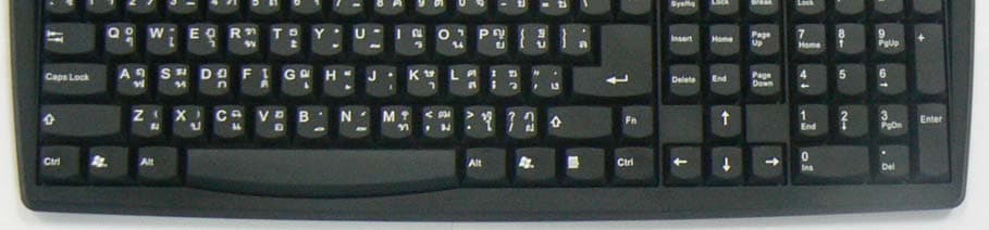
Click to zoom
Application Details
- Equipment Class
- JBC - Part 15 Class B Computing Device/Personal Computer
- Date of Grant
- Jan 29, 2007
- Application Purpose
- Original Equipment
- Date of Application
- Jan 29, 2007
- Equipment Note
- PERSONAL COMPUTER
- Country
- Thailand
Documents & Files
Document Text
Text extracted from the exhibit documents filed with the FCC. Open a document above to read the original.
Users Manual
Computer Operation Manual Contents Page 1. PRODUCT INFORMATION 1 2. Installation of the computer 2 Components of the computer 2 Accessories that comes in the box 3 Ports used to connect the computer with the peripherals. 4 3. Procedures to install the computer 5 4. Maintenance of the computer 8 5. General uses and safety precautions 9 6. Service centers 10 - 1 - 1. PRODUCT INFORMATION NOTE: THE MANUFACTURER IS NOT RESPONSIBLE FOR ANY RADIO OR TV INTERFERENCE CAUSED BY UNAUTHORIZED MODIFICATIONS TO THIS EQUIPMENT. SUCH MODIFICATIONS COULD VOID THE USER'S AUTHORITY TO OPERATE THE EQUIPMENT FCC GUIDELINES WARNING: This equipment has been tested and found to comply with the limits for a Class B digital device, pursuant to part 15 of the FCC Rules. These limits are designed to provide reasonable protection against harmful interference in a residential installation. This equipment generates, uses and can radiate radio frequency energy and, if not installed and used in accordance with the instructions, may cause harmful interference to radio communications. However, there is no guarantee that interference will not occur in a particular installation. If this equipment does cause harmful interference to radio or television reception, which can be determined by turning the equipment off and on, the user is encouraged to try to correct the interference by one or more of the following measures: - Reorient or relocate the receiving antenna. - Increase the separation between the equipment and receiver. -Connect the equipment into an outlet on a circuit different from that to which the receiver is connected. -Consult the dealer or an experienced radio/TV technician for help. - 2 - 2. Installation of the computer Components of the computer 1. Computer 2. Monitor 3. Keyboard 4. Mouse 5. Speaker 3 4 2 5 1 - 3 - Accessories that come in the box 1. Main board + CD drive 2. Telephone cord 3. Electrical cords 4. Mouse pad 5. Case cover Remark: There may be some change based on the details of each model. 1 2 3 4 5 - 4 - Ports used to connect the computer with the peripherals. 1. Green connecting with the Mouse port. 2. Purple connecting with the Keyboard port. 3. USB ports, e.g. printer, scanner. 4. LAN port for connecting to the network 5. Serial port, e.g. external modem, printer. 6. Parallel port for connecting with the printer 7. marine VGA port for connecting with the monitor 8. green port connecting Speaker port 9. sky blue line-in port used to connect the audio signal with the external source. Radio. 10. MIC (microphone) port 11. Game port used to connect with the game console,e.g. joy stick. 12. Line port to connect the telephone line for interfacing with the Internet 13. Phone port for connecting the computer to the telephone in case of not using the Internet as in the diagram. 12 87 3 9 10 611 4 5 13 12 - 5 - 3. Steps of installation the computer 3.1 Install the mouse by using the green cord connects to the green port in the back of the computer as shown in figure. 1 Figure 1 3.2 Install the keyboard by using the end of the purple line connects to the back of the computer as shown in figure. 2 Figure 2 - 6 - 3.3 Install the monitor by using the end of the blue cord to connect the blue port on the back of the computer as shown in figure. 3 Figure 3 3.4 Install the speaker by end of the green cord to connect the port on the back of the computer as shown in figure. 4 Figure 4 3.5 Connect the telephone line to the modem using the telephone jack to insert in the LINE port. If you want to connect the telephone together. Use the telephone line connects with the phone port as shown in figure. 5. Figure 5 - 7 – 3.6 Connect the cable of the computer to the power supply on the back of the computer as in figure.6 Figure.6 3.7 After the connections in number 1-6 already, press on the power switch in the middle to turn on the computer. Figure 7 - 8 - 4. Maintenance of the computer Procedures on maintenance of the computer 4.1 External cleaning 4.1.1. Before cleaning the computer externally Case, Monitor, Keyboard , Mouse , Speaker the precautions should be exercised. By removing the power – supply line each time to prevent from electrical shock. 4.1.2. Then use a cleaning solution, available from the general stores, to wipe the computer externally. Avoid the solutions with a mixture of thinner of concentrated alcohol of chemical that may cause damage to the computer. 4.2 Internal cleaning 4.2.1. Before cleaning the inside of the computer, the power supply line should be removed from the outlet each time to prevent an electrical shock. 4.2.2. Prepare the cleaning kits, including a screw driver (for opening the case cover), a vacuum cleaner, clean cloth, brush (for dusting) , finish – cleaning solution (for wiping Floppy disk CD ), which available at the general stores. 4.2.3. After removing the cords. Take the computer to the prepared place open the computer case, then use the vacuum or blow out dust from the computer. For the inaccessible parts use a brush to dust out. Use a cloth rag to clean the parts that are inaccessible. Avoid or be careful not to allow the components and internal cords to come loose, as they may cause possible damage. 4.2.4. After cleaning is completed, check the internal components to make sure they are in the old condition. Then close the case to finish it. 4.2.5. Bring the cleaned computer to install in the old position, connect the signal wires to the old positions or comply with the installation manual, then turn it on the check if it can work normally or not. 4.2.6. After the computer can be used normally, clean it using Floppy Disk, CD-Rom the cleaning equipment prepared and comply with the manual that crones each peripheral. 4.2.7. After cleaning it you cannot use it or there is a problem, contact the service center of the company at the telephone number 02-235-7000 Warning: You should have the service center check the battery installed on the main circuit whether or not it has suffi…
Text truncated - open the document above for the full version.
Block Diagram
OPTIMA Series Block Diagrams Monitor Mainboard PowersupplyFDD Module HDD Module PCI Device CDRom Module Keyboard Mouse System Block Diagram Mainboard Diagram
External Photos
OPTIMA Series External Photos Front Rear Left Right Front Rear Left Right Mouse Key board
ID Label/Location Info
OPTIMA Series FCC ID label location information FCC ID Label Location
ID Label/Location Info
OPTIMA Series FCC ID label sample FCC ID Label
Internal Photos
OPTIMA Series Internal Photos CPU case Power Supply Main Board CPU Hard Disk RAM Floppy Disk CD-Rom
Test Report
REPORT No. 013 / 50-10 Page 2 of 27 This test report is test results from the EUT only, not the product’s quality certificate. It shall not be reproduced except in full without the written approval of testing laboratory. Electrical and Electronic Products Testing Center National Science and Technology Development Agency, Ministry of Science and Technology PTEC Building, King Mongkut’s Institute of Technology Ladkrabang, Chalongkrung Road, Ladkrabang, Bangkok, Thailand 10520 Tel. +66-2739-2188..96, Fax +66-2739-2199, website www.ptec.or.th PTEC-02-03-013 REV.15/15-08-06 CONTENTS SUMMARY OF TESTING 3 1. TEST PLAN AND DEVIATIONS FROM STANDARD 4 2.1 Test Plan 4 2.2 Deviations from standard 4 3 TEST CONDITIONS 5 3.1 Operation Mode 5 3.2 Uncertainty Application 5 3.3 Equipment Classifications 7 3.4 Protection Classifications 7 3.5 Performance Criteria of Test Specification 7 3.6 EUT Function Monitoring 7 4 TEST SYSTEM CONFIGURATION 7 4.1 EUT Exercise Software 7 4.2 EUT Modifications 7 5. EUT DESCRIPTION 8 5.1 EUT Specification 8 5.2 EUT Configuration 9 5.3 Peripherals Description 9 5.4 Cables Description 9 6 TEST SETUP AND RESULT 10 6.1 Test Item : Conducted Emission 10 6.2 Test Item : Radiated Disturbance 14 7 APPENDIX 18 REPORT No. 013 / 50-10 Page 3 of 27 This test report is test results from the EUT only, not the product’s quality certificate. It shall not be reproduced except in full without the written approval of testing laboratory. Electrical and Electronic Products Testing Center National Science and Technology Development Agency, Ministry of Science and Technology PTEC Building, King Mongkut’s Institute of Technology Ladkrabang, Chalongkrung Road, Ladkrabang, Bangkok, Thailand 10520 Tel. +66-2739-2188..96, Fax +66-2739-2199, website www.ptec.or.th PTEC-02-03-013 REV.15/15-08-06 SUMMARY OF TESTING This product was tested and complied according to following specification standard: FCC Part 15 Radio frequency devices Test Item Test Specification Test Method Result Conducted Emission FCC Part 15 Subpart B Section 15.107(a) ANSI C63.4-2003 PASS Radiated Disturbance FCC Part 15 Subpart B Section 15.109(a) ANSI C63.4-2003 PASS REPORT No. 013 / 50-10 Page 4 of 27 This test report is test results from the EUT only, not the product’s quality certificate. It shall not be reproduced except in full without the written approval of testing laboratory. Electrical and Electronic Products Testing Center National Science and Technology Development Agency, Ministry of Science and Technology PTEC Building, King Mongkut’s Institute of Technology Ladkrabang, Chalongkrung Road, Ladkrabang, Bangkok, Thailand 10520 Tel. +66-2739-2188..96, Fax +66-2739-2199, website www.ptec.or.th PTEC-02-03-013 REV.15/15-08-06 1. TEST PLAN AND DEVIATIONS FROM STANDARD 2.1 Test Plan No. Test Item Input Voltage Mode Test Port Test Specification 1 Conducted Emission 110 Vac 60 Hz A AC Main FCC Part 15 Subpart B Section 15.107(a) 2 Radiated Disturbance 110 Vac 60 Hz A Enclosure FCC Part 15 Subpart B Section 15.109(a) 2.2 Deviations from standard - REPORT No. 013 / 50-10 Page 5 of 27 This test report is test results from the EUT only, not the product’s quality certificate. It shall not be reproduced except in full without the written approval of testing laboratory. Electrical and Electronic Products Testing Center National Science and Technology Development Agency, Ministry of Science and Technology PTEC Building, King Mongkut’s Institute of Technology Ladkrabang, Chalongkrung Road, Ladkrabang, Bangkok, Thailand 10520 Tel. +66-2739-2188..96, Fax +66-2739-2199, website www.ptec.or.th PTEC-02-03-013 REV.15/15-08-06 3 TEST CONDITIONS 3.1 Operation Mode A: Run Burn in Software (PC. Performance Test). 3.2 Uncertainty Application 3.2.1 Uncertainty application according to CISPR 16-4-2:2003 for Conducted Emission , Radiated Disturbance and Disturbance Power Testing. Compliance or Non-Compliance with a disturbance limit was determined in the following manner If U lab is less than or equal to U cispr in table 1, then: - Compliance is deemed to occur if no measured disturbance exceeds the disturbance limit. - Non-Compliance is deemed to occur if any measured disturbance exceeds the disturbance limit. If U lab is greater than U cispr in table 1, then: - Compliance is deemed to occur if no measured disturbance, increased by ( U lab - U cispr ), exceeds the disturbance limit. - Non-Compliance is deemed to occur if any measured disturbance, increased by ( U lab -U cispr ), exceeds the disturbance limit. Table 1 – Values of U cispr Abbreviation Testing system Frequency range U lab U cispr U lab - U cispr CE Conducted Emission 9 kHz - 150 kHz 3.41 4.00 -0.59 CE Conducted Emission 150 kHz - 30 MHz 2.98 3.60 -0.62 RE Radiated Disturbance 30 MHz – 1000 MHz 4.53 5.20 -0.67 PE Disturbance Power 30 MHz – 300 MHz 3.90 4.50 -0.60 REPORT No. 013 / 50-10 Page 6 of 27 This test report is test results from the EUT only, not the product’s quality certificate. It shall not be reproduced except in full without the written approval of testing laboratory. Electrical and Electronic Products Testing Center National Science and Technology Development Agency, Ministry of Science and Technology PTEC Building, King Mongkut’s Institute of Technology Ladkrabang, Chalongkrung Road, Ladkrabang, Bangkok, Thailand 10520 Tel. +66-2739-2188..96, Fax +66-2739-2199, website www.ptec.or.th PTEC-02-03-013 REV.15/15-08-06 Frequency 10 This is the estimated uncertainty of our applied level. We have at least 95 % confidence that the actual applied level is In this range but only a 50 % confidence that the required level has been reached. Required Immunity Test level to apply which gives a 95 % confidence that specified level has been achieved is the standard uncertainty multiplied by a factor k=1.64 3.2.2 Uncertainty Application according to LAB 34 Edition 1 ( Figure 1 ) for other testing system. Pass Case A The measured result is within the limit, even when extended by the uncertain…
Text truncated - open the document above for the full version.
Test Setup Photos
OPTIMA Series Test Set-up Photos Conducted Emission Radiated Disturbance
Contact Information
Applicant
Somphop Thongnumsap
Test Firm
PTECYothin Prempraneerach
Technical Specifications
| # | Rule Parts | Frequency Range | Power Output |
|---|---|---|---|
| 1 | 15B | - | - |