UPCDBRF15Wireless Sensor
St. Michael Strategies Inc.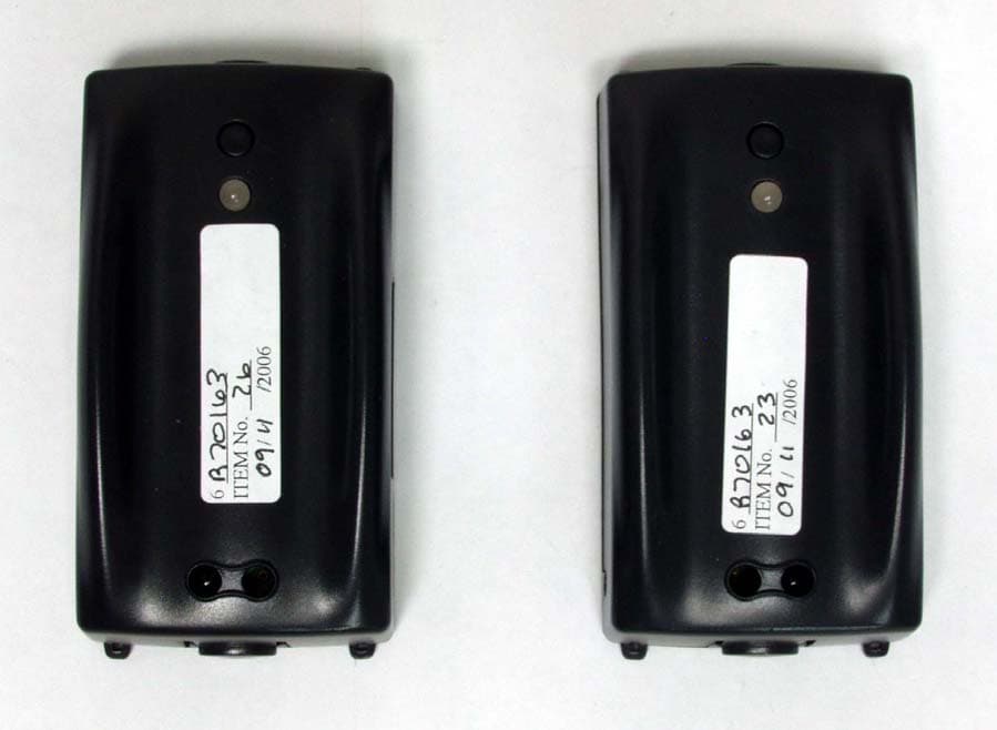
Click to zoom
Application Details
- Equipment Class
- DXT - Part 15 Low Power Transceiver, Rx Verified
- Date of Grant
- Dec 11, 2006
- Application Purpose
- Original Equipment
- Date of Application
- Dec 11, 2006
- Equipment Note
- Wireless Sensor
- Frequency Range
- 2408.00000000 - 2475.00000000
- Company
- St. Michael Strategies Inc.
- Country
- Canada
Documents & Files
Document Text
Text extracted from the exhibit documents filed with the FCC. Open a document above to read the original.
Users Manual
Installation Manual DBRF 15-01Wireless Sensors 701 Salaberry, Chambly, Quebec J3L 1R2 Canada Phone: (450) 658-5148 Fax: (450) 658-7764 Wireless Sensors (DBRF 15-01) Important: Sensors must be installed so that the beam is at 54 inches from the ground. Step 1: Turning the sensors ON • Both the receiver and the transmitter come with a holder or holster. To remove the actual unit from the holster you need to remove the set screw with a screw driver. The set screw prevents the sensor from being removed from the holster. Remember to replace the set screw to lock the sensor into the holster. To remove the sensor from the holster, remove the set screw, then hold the unit in one hand and press on the top release pad to release the unit, and then remove the sensor from the holster. E-mail: [email protected] Web: www.storetraffic.com Installation Manual DBRF 15-01Wireless Sensors 701 Salaberry, Chambly, Quebec J3L 1R2 Canada Phone: (450) 658-5148 Fax: (450) 658-7764 E-mail: [email protected] Web: www.storetraffic.com holster sensor Installation Manual DBRF 15-01Wireless Sensors 701 Salaberry, Chambly, Quebec J3L 1R2 Canada Phone: (450) 658-5148 Fax: (450) 658-7764 E-mail: [email protected] Web: www.storetraffic.com Installation Manual DBRF 15-01Wireless Sensors 701 Salaberry, Chambly, Quebec J3L 1R2 Canada Phone: (450) 658-5148 Fax: (450) 658-7764 E-mail: [email protected] Web: www.storetraffic.com Step 2: Setting the Sensors to Front or Side Firing (dia. 1) (dia.2) (dia.3) (dia.4) Side firing beam Front firing beam Installation Manual DBRF 15-01Wireless Sensors 701 Salaberry, Chambly, Quebec J3L 1R2 Canada Phone: (450) 658-5148 Fax: (450) 658-7764 E-mail: [email protected] Web: www.storetraffic.com Identify front or side firing configuration • Sensors can be configured to be either front or side firing. This is important and allows you the flexibility to install the sensors. If you need to align the sensors so they face each other, this is front firing, and front firing is usual if installed on the inside of a door frame (dia.1) (dia.3) (dia.5) (dia.6) or side firing if placed on outside of the door frame (dia,2) (dia.4) (dia.7) (dia.8). • Each set of sensors consists of a receiver and a transmitter. The receiver is the one with the LCD screen, which register the counts and communicates with the STC. The transmitter is the one projecting the Infra-red beam. dia.5 dia.6 Installation Manual DBRF 15-01Wireless Sensors 701 Salaberry, Chambly, Quebec J3L 1R2 Canada Phone: (450) 658-5148 Fax: (450) 658-7764 E-mail: [email protected] Web: www.storetraffic.com dia. 7 dia. 8 • As seen in the pictures above, the sensors can be installed in front firing or side firing configuration. A switch in the back of each sensor (allows it to be configured accordingly. When changing the firing configuration please move the switch gently to the middle, and then move it in the desired direction. Both switches must be set to either front or side firing position to be on. If the switch is left in the middle, the sensors are off and are not operating. Installation Manual DBRF 15-01Wireless Sensors 701 Salaberry, Chambly, Quebec J3L 1R2 Canada Phone: (450) 658-5148 Fax: (450) 658-7764 E-mail: [email protected] Web: www.storetraffic.com Front firing Side firing (dia. 9) • In a side firing configuration, the receiver’s LCD screen must not be pointing in the direction of the other sensor. The transmitter has a rectangle cutout in the transmitter. This side needs to be pointing in the direction of the receiver. Please refer to the following drawing. Installation Manual DBRF 15-01Wireless Sensors 701 Salaberry, Chambly, Quebec J3L 1R2 Canada Phone: (450) 658-5148 Fax: (450) 658-7764 E-mail: [email protected] Web: www.storetraffic.com • Wireless equipment is sensible to strong interference sources such as a breaker box, transformers, computer screen. Please install the STC as far away from these sources as possible. Installation Manual DBRF 15-01Wireless Sensors 701 Salaberry, Chambly, Quebec J3L 1R2 Canada Phone: (450) 658-5148 Fax: (450) 658-7764 E-mail: [email protected] Web: www.storetraffic.com Step 3: Pre-installation instructions • The sensors should be installed in a way to allow the IR beam to be at 54 inches from the ground, as shown in the picture above. This is to avoid counting strollers, carts and children under 54 inches. • The sensors can either be screwed to the wall or mounted using double-sided tape. Please contact SMS for information on double-sided tape. Peel-off tape mounting plate can be provided by SMS. • In side firing configuration, the receiver LCD screen must not be pointing in the direction of the other sensor. The transmitter has rectangle cutout in the transmitter. This side needs to be pointing in the direction of the receiver. Please refer to the picture at the top-right of the page. Installation Manual DBRF 15-01Wireless Sensors 701 Salaberry, Chambly, Quebec J3L 1R2 Canada Phone: (450) 658-5148 Fax: (450) 658-7764 E-mail: [email protected] Web: www.storetraffic.com • The sensor should not be more than 15 feet apart. • Ensure that the doors open out only and do not cross the infrared beam when they open. • Ensure that the door handle is not blocking the RF sensor’s infrared beam. • Ensure the back part of the door, where the hinges are generally mounted, are not blocking the RF sensor’s infrared beam. • Make sure that there is no merchandiser, posters, stands, greeter or security person standing blocking the beam. Installation Manual DBRF 15-01Wireless Sensors 701 Salaberry, Chambly, Quebec J3L 1R2 Canada Phone: (450) 658-5148 Fax: (450) 658-7764 E-mail: [email protected] Web: www.storetraffic.com Step 4: Installation: • Install the holster for the transmitter so that the infra-red beam is at 54 inches from the ground. • Put the sensor back in its holster. • Press the button once and the LED will glow green. This means the sensors are on. • T…
Text truncated - open the document above for the full version.
ID Label/Location Info
Label Location Product DBRF15-01 FCC ID: UPCDBRF15 Label size: 1,10” X 1,968” Label Location
Test Report
FCC Part 15 Subpart C, 15.249 : August 2005 Test Report: 6W70163.2 Applicant: ST.Michael Strategies 701, Salaberry St., Suite 201, Chambly, Quebec, J3L 1R2 Apparatus: STC-W200 Sensor FCC ID: UPCDBRF15 In Accordance With: FCC Part 15 Subpart C, 15.249 Operation in the 902-928MHz, 2400-2483.5 MHz, 5725-5850MHz and 24.0-24.25 GHz Tested By: Nemko Canada Inc. 303 River Road Ottawa, Ontario K1V 1H2 Authorized By: Xu Jin, Wireless Specialist Date: November 23, 2006 Total Number of Pages: 19 Nemko Canada Inc. REPORT SUMMARY Report Number: 6W70163.2 FCC ID: UPCDBRF15 Specification: FCC Part 15 Subpart C, 15.249 Page 2 of 19 Report Summary These tests were conducted on a sample of the equipment for the purpose of demonstrating compliance with Part 15, Subpart C. Radiated tests were conducted in accordance with ANSI C63.4-2003. Radiated emissions are made on an open area test site. A description of the test facility is on file with the FCC. The assessment summary is as follows: Apparatus Assessed: STC-W200 Sensor Specification: FCC Part 15 Subpart C, 15.249 Compliance Status: Complies Exclusions: None Non-compliances: None Report Release History: Original Release Author: Roman Kuleba, EMC/Wireless Specialist Note that the results contained in this report relate only to the items tested and were obtained in the period between the date of initial receipt of samples and the date of issue of the report. This test report has been completed in accordance with the requirements of ISO/IEC 17025. Nemko Canada Inc. authorizes the applicant to reproduce this report provided it is reproduced in its entirety and for use by the company’s employees only. Any use which a third party makes of this report, or any reliance on or decisions to be made based on it, are the responsibility of such third parties. Nemko Canada Inc. accepts no responsibility for damages, if any, suffered by any third party as a result of decisions made or actions based on this report. Nemko Canada Inc. REPORT SUMMARY Report Number: 6W70163.2 FCC ID: UPCDBRF15 Specification: FCC Part 15 Subpart C, 15.249 Page 3 of 19 TABLE OF CONTENTS Report Summary......................................................................................................................................... 2 Section 1 : Equipment Under Test............................................................................................................. 4 1.1 Product Identification .................................................................................................................................4 1.2 Samples Submitted for Assessment............................................................................................................4 1.3 Theory of Operation ...................................................................................................................................4 1.4 Technical Specifications of the EUT ..........................................................................................................5 1.5 Block Diagram of the EUT.........................................................................................................................5 Section 2 : Test Conditions......................................................................................................................... 6 2.1 Specifications .............................................................................................................................................6 2.2 Deviations From Laboratory Test Procedures ............................................................................................6 2.3 Test Environment .......................................................................................................................................6 2.4 Test Equipment...........................................................................................................................................6 Section 3 : Observations ............................................................................................................................. 7 3.1 Modifications Performed During Assessment ............................................................................................7 3.2 Record Of Technical Judgements ...............................................................................................................7 3.3 EUT Parameters Affecting Compliance .....................................................................................................7 3.4 Test Deleted................................................................................................................................................7 3.5 Additional Observations .............................................................................................................................7 Section 4 : Results Summary ..................................................................................................................... 8 4.1 FCC Part 15 Subpart C : Test Results ........................................................................................................9 Appendix A : Test Results ........................................................................................................................ 10 Clause 15.215(c) Occupied Bandwidth ...............................................................................................................10 Clause 15.209(a) Radiated Emissions within Restricted Bands ..........................................................................11 Clause 15.249(a) & (d) Radiated emissions not in Restricted Bands ..................................................................16 Appendix B : Setup Photographs ............................................................................................................ 18 Appendix C : Block Diagram of Test Setups .......................................................................................... 19 Nemko …
Text truncated - open the document above for the full version.
Contact Information
Applicant
Dominic Sicard
Technical Contact
Non-Technical Contact
St. Michael StrategiesDominic Sicard
[email protected]450 658 5148
Test Firm
Nemko Canada Inc. (Ottawa)Charles Neal
Technical Specifications
| # | Rule Parts | Frequency Range | Power Output |
|---|---|---|---|
| 1 | 15C | 2.41 GHz - 2.48 GHz | - |
Other Applications from St. Michael Strategies Inc.
UPCHOST01
Dec 11, 2006Wireless Traffic Collector
Equipment Class
DXT - Part 15 Low Power Transceiver, Rx Verified