URLBRP64MSLOW POWER TRANSMITTER
Go Radio, LLC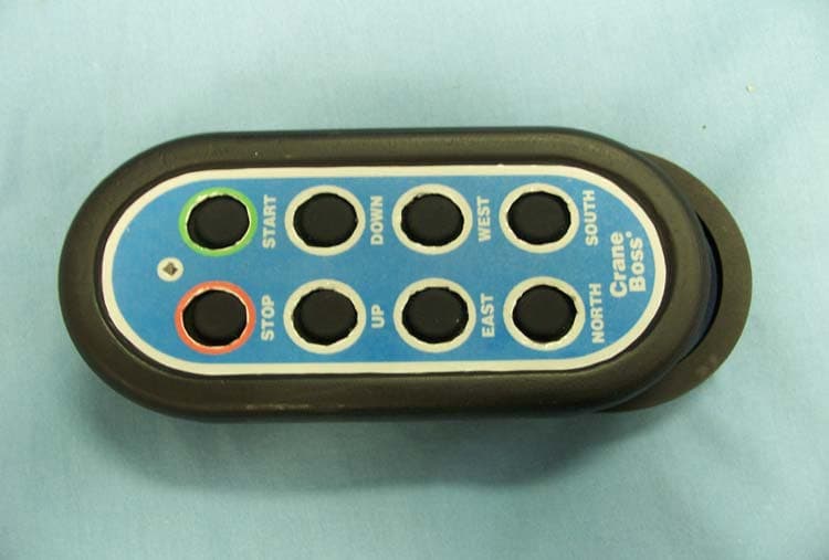
Click to zoom
Application Details
- Equipment Class
- DSC - Part 15 Security/Remote Control Transmitter
- Date of Grant
- Feb 07, 2007
- Application Purpose
- Original Equipment
- Date of Application
- Feb 07, 2007
- Equipment Note
- LOW POWER TRANSMITTER
- Frequency Range
- 422.40000000 - 472.40000000
- Company
- Go Radio, LLC
- Country
- United States
Documents & Files
Document Text
Text extracted from the exhibit documents filed with the FCC. Open a document above to read the original.
Users Manual
TR1000 GoRadio 1914 Silver Street Garland, TX 75042 USA Page 1 of 15 OPERATION & INSTALLATION MANUAL Go Radio Model No. TR1000 December, 2006 TR1000 GoRadio 1914 Silver Street Garland, TX 75042 USA Page 2 of 15 Table of Contents Table of Contents....................................................................................................2 1 General Information..........................................................................................3 1.1 Scope.......................................................................................................3 1.2 System Description....................................................................................3 1.2.1 General................................................................................................. 3 1.2.2 Control Functions...................................................................................3 1.3 Warranty.................................................................................................. 4 2 Operation.........................................................................................................4 2.1 Receiving Equipment.................................................................................4 2.2 Transmitter...............................................................................................4 2.3 Operating Procedure..................................................................................4 3 Installation.......................................................................................................5 3.1 Scope.......................................................................................................5 3.2 Receiving Assembly ..................................................................................6 3.3 Transmitter Installation..............................................................................6 4 Maintenance.....................................................................................................7 4.1 Preventive Maintenance.............................................................................7 4.2 Corrective Maintenance..............................................................................7 4.3 Replaceable Parts......................................................................................7 5 Specifications....................................................................................................7 5.1 Electrical................................................................................................... 7 5.1.1 Transmitter...........................................................................................7 5.1.2 Receiver................................................................................................7 5.2 Temperature.............................................................................................9 5.2.1 Operating..............................................................................................9 5.2.2 Storage................................................................................................. 9 5.3 Environmental...........................................................................................9 6 Appendices.....................................................................................................10 6.1 Fuses ....................................................................................................10 TR1000 GoRadio 1914 Silver Street Garland, TX 75042 USA Page 3 of 15 1 General Information 1.1 Scope This manual contains information necessary to install, operate and maintain the GoRadio TR1000 system. Read all OSHA related guidelines for your industry before operating this product. FCC I.D.: URLBRP64MS This device complies with Part 15 of the FCC Rules. Operation is subject to the following two conditions: (1) this device may not cause harmful interference, and (2) this device must accept any interference received, including interference that might cause undesired operation. The manufacturer is not responsible for any radio or TV interference caused by unauthorized modifications to this equipment. Such modifications could void the user’s authority to operate the equipment. 1.2 System Description 1.2.1 General The TR1000 System is a wireless remote control system for light industrial use. It consists of one 115/230 VAC powered receiving assembly and one hand-held battery powered 8-button transmitter unit. 1.2.2 Control Functions There are 8 control functions on the transmitter in mutually exclusive pairs. These functions are labeled: START / STOP UP / DOWN EAST / WEST NORTH / SOUTH There are 8 control relays and 9relay outputs in the Receiving Assembly. These outputs are labeled: COMMON / START UP / DOWN EAST / WEST NORTH / SOUTH The START relay has both Normally Open (N.O.) and Normally Closed (N.C.) outputs. The COMMON relay is in series with all the other relays. The COMMON re lay is fused at TR1000 GoRadio 1914 Silver Street Garland, TX 75042 USA Page 4 of 15 10 amps nominal. It is connected between the COMMON input and the input of all other relays as well as its own MAIN output. The receiving assembly is labeled showing the relay connections and the wiring of the exit cable. This includes the power, and all wiring to and from the relays. 1.3 Warranty The manufacturer warrants the delivered system to be free of defective material and workmanship. It will remedy any such defect within one year of first party purchase at no charge to the purchaser upon return to the factory. Defects caused by improper installation, maintenance, misuse, tampering, neglect, accident, or use in violation of manufacturer’s written instructions shall not be covered in this warranty. Manufacturer guarantees the system will perform as outlined in this manual. Transfer of this warranty is acceptable and recommended. Please notify the factory of any and all transfers. 2 Operation 2.1 Receiving Equipment…
Text truncated - open the document above for the full version.
ID Label/Location Info
STOPSTART UP DOWN EASTWEST NORTHSOUTH Serial No.: IC: 6910A-BRP64MS FCC ID: URLBRP64MS Model: TR1000 Go Radio
Test Report
Nemko Test Report: 6L0429RUS1 Applicant: GoRadio, LLC 1914 Silver Street Garland, Texas 75042 USA Equipment Under Test: TR1000 (E.U.T.) In Accordance With: FCC Part 15, Subpart C For Low Power Transmitters Operating Periodically In The Band 40.66 - 40.77 MHz And Above 70 MHz Tested By: Nemko USA, Inc. 802 N. Kealy Lewisville, TX 75057-3136 TESTED BY: DATE: 24 October 2006 David Light Wireless Engineer APPROVED BY: DATE: 26 October 2006 Kevin Rose Wireless Engineer Total Number of Pages: 21 Nemko USA, Inc. FCC PART 15, SUBPART C PERIODICALLY OPERATED LOW POWER TRANSMITTERS EQUIPMENT: TR1000 PROJECT NO.: 6L0429RUS1 Page 2 of 21 TABLE OF CONTENTS SECTION 1. SUMMARY OF TEST RESULTS 3 SECTION 2. EQUIPMENT UNDER TEST (E.U.T.) 5 SECTION 3. TRANSMISSION REQUIREMENTS 7 SECTION 4. RADIATED EMISSIONS 10 SECTION 5. OCCUPIED BANDWIDTH 14 SECTION 6. BLOCK DIAGRAMS 16 SECTION 7. TEST EQUIPMENT LIST 19 ANNEX A - RESTRICTED BANDS 20 Nemko USA, Inc. FCC PART 15, SUBPART C PERIODICALLY OPERATED LOW POWER TRANSMITTERS EQUIPMENT: TR1000 PROJECT NO.: 6L0429RUS1 Page 3 of 21 Section 1. Summary of Test Results Manufacturer: GoRadio, LLC Model No.: TR1000 Serial No(s): 0001, 0002, 0003 General: All measurements are traceable to national standards. These tests were conducted on a sample of the equipment for the purpose of demonstrating compliance with Part 15, Subpart C, Paragraph 15.231. All tests were conducted using measurement procedure ANSI C63.4-2003. Radiated emissions are made on an open area test site. A description of the test facility is on file with the FCC. New Submission Production Unit Class II Permissive Change Pre-Production Unit THIS TEST REPORT RELATES ONLY TO THE ITEM(S) TESTED. THE FOLLOWING DEVIATIONS FROM, ADDITIONS TO, OR EXCLUSIONS FROM THE TEST SPECIFICATIONS HAVE BEEN MADE. See “ Summary of Test Data”. Nemko USA Inc. authorizes the above named company to reproduce this report provided it is reproduced in its entirety and for use by the company’s employees only. Any use which a third party makes of this report, or any reliance on or decisions to be made based on it, are the responsibility of such third parties. Nemko USA Inc. accepts no responsibility for damages, if any, suffered by any third party as a result of decisions made or actions based on this report. This report applies only to the items tested. Nemko USA, Inc. FCC PART 15, SUBPART C PERIODICALLY OPERATED LOW POWER TRANSMITTERS EQUIPMENT: TR1000 PROJECT NO.: 6L0429RUS1 Page 4 of 21 Summary Of Test Data Name of Test Paragraph No. Results Transmission Requirements 15.231(a) Complies Radiated Emissions 15.231(b) Complies Occupied Bandwidth 15.231(c) Complies Frequency Tolerance 15.231(d) NA Alternate Field Strength Requirements 15.231(e) NA Powerline Conducted Emissions 15.207 NA Footnotes: The device does not operate in the band 40.66-40.70 MHz The device is battery powered. Nemko USA, Inc. FCC PART 15, SUBPART C PERIODICALLY OPERATED LOW POWER TRANSMITTERS EQUIPMENT: TR1000 PROJECT NO.: 6L0429RUS1 Page 5 of 21 Section 2. Equipment Under Test (E.U.T.) General Equipment Information Frequency Range: 422.4 to 472.4 Operating Frequency(ies) of Sample: 422.4, 433.0, and 472.4 MHz Type of Emission: GFSK Supply Power Requirement: Two AA Batteries Duty Cycle Correction Factor: -21.5 dB Nemko USA, Inc. FCC PART 15, SUBPART C PERIODICALLY OPERATED LOW POWER TRANSMITTERS EQUIPMENT: TR1000 PROJECT NO.: 6L0429RUS1 Page 6 of 21 Description of E.U.T. The GoRadio industrial remote controller design is based on a Nordic nRF9E5 chip with fully integrated microcontroller, RF transceiver, multiple input high resolution analog to digital converter (ADC), and internal voltage regulator. The industrial remote controller system consists of a “listen only” stationary receiver unit and mobile “transmit only” controller. Both units function as a complete system with programmable channels to prevent jamming during operation. System Diagram Nemko USA, Inc. FCC PART 15, SUBPART C PERIODICALLY OPERATED LOW POWER TRANSMITTERS EQUIPMENT: TR1000 PROJECT NO.: 6L0429RUS1 Page 7 of 21 Section 3. Transmission Requirements NAME OF TEST: Transmission Requirements PARA. NO.: 15.231(a) TESTED BY: David Light DATE: 23 October 2006 Minimum Standard: 15.231(a) Continuous transmissions such as voice, video or data transmissions are not permitted. 15.231(a)(1) A manually operated transmitter shall employ a switch that will automatically deactivate the transmitter within not more than 5 seconds after being released. 15.231(a)(2) A transmitter activated automatically shall cease transmission within 5 seconds of activation. 15.231(a)(3) Periodic transmissions at regular pre- determined intervals are not permitted. However polling or supervisory transmissions to determine system integrity of transmitters used in security or safety applications are allowed if the periodic rate of transmission does not exceed one transmission of not more than one second duration per hour for each transmitter. 15.231(a)(4) Intentional radiators which are employed for radio control purposes during emergencies involving fire, security, and safety of life, when activated to signal an alarm, may operate during the pendency of the alarm. Test Results: Complies. Test Data: Compliance was determined by verification of technical specifications and a functional test on the equipment. Nemko USA, Inc. FCC PART 15, SUBPART C PERIODICALLY OPERATED LOW POWER TRANSMITTERS EQUIPMENT: TR1000 PROJECT NO.: 6L0429RUS1 Page 8 of 21 Rationale for Compliance with Transmission Requirements Manual activation 15.231(a)(1) 15.231(a)(2) : Automatic activation TX deactivation time: Regular, predetermined transmissions 15.231(a)(3) : Polling or supervisory transmissions TX rate and duration: Alarm device operating during the pendancy of alarm condition 15.231(a)(4) : Non-alarm device Nemko USA, Inc. FCC PART 15, SUBPART C PERIODICALLY OPERATED LOW POWER TRANSMITTERS EQUIPMENT: TR1000 PROJECT NO.: 6L0429RUS1 Page 9 of 21 Test Da…
Text truncated - open the document above for the full version.
Test Setup Photos
Radiated Photographs
Contact Information
Applicant
William B Robinson(President)
Test Firm
Nemko Dallas, Inc.Michael Cantwell
Technical Specifications
| # | Rule Parts | Frequency Range | Power Output |
|---|---|---|---|
| 1 | 15.231 | 422.4 MHz - 472.4 MHz | - |