UTMIXTWM100WIRELESS MICROPHONE
IXT Systems dba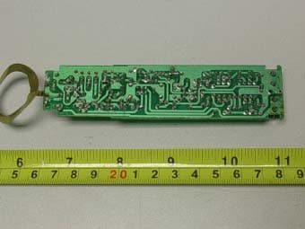
Click to zoom
Application Details
- Equipment Class
- TBF - Licensed Broadcast Transmitter Held to Face
- Date of Grant
- Dec 13, 2006
- Application Purpose
- Original Equipment
- Date of Application
- Dec 13, 2006
- Equipment Note
- WIRELESS MICROPHONE
- Frequency Range
- 181.70000000 - 215.80000000
- Company
- IXT Systems dba
- Country
- United States
Documents & Files
Document Text
Text extracted from the exhibit documents filed with the FCC. Open a document above to read the original.
Users Manual
User Guide and Reference Manual WM-320 We greatly appreciate your purchase of the WM-320 To be sure you take maximum advantage of all the WM-320 has to offer, read these instruction carefully an use the set properly .Be sure to keep this manual for future reference ,should any questions or problems arise . Catalogue Catalogue Main function 2 Control and function (receiver) 3 Control and function (microphone) 4 Operation of the receiver 5 Operation of microphone 6 Repair with simple fault 6 Specification 7 Frequency response 8 Body pack transmitter (accessories) 9 Matters needing attention 10 1 Main function Main function using VHF 181-216 MHz band to avert interfering frequency using multilevel high frequency and mid frequency narrowband filter ,so as to dispel any possible signals There is a volt indicating circuit in the microphone it can tell you if it is necessary to change the battery A specially designed circuit switch is on the phone .It is for clearing up waves of miscellaneous the dynamic range .It can also lower reecho . The receiver use multilevel high frequency enlarger so it has high sensitivity. It has channel separate outputting and mix outputting and it can be connected with sound-adjusting stage and the Karaoke enlarger. Special tone keyer locked identity functions to avoid interference signal from outside open the mute system There are mulriple noise detect circuit function to avoid interference signal from outside open the mute system There are mulriple noise detect circuit ,multi-circuit so it has strong anti-jamming specially Choose excellent chipset and high quality component so that its timbre will be very good Longest distance in open :80 ideal distance in open :60M Frequency response tailored for vocals ,with brightened midrange and bass roll-off Uniform cardioid pick up pattern isolates the main sound source and minimizes background noise Effective ,built-in spherical wind and pop filter It is suitable for small and large stages /ballrooms auditoria classrooms and families Unprecedented echo circuit ,make the machine more characteristic Advanced dual wire microphone input ,make the user more comfortable Additional AF& video switching line ,make the range of uses more wide . 2 Function introduction Front panel &real panel 1. power /echo switch :Turn the receiver ON and OFF &adjust the echo 2. A/B wireless microphone volume :adjust the volume of wireless microphone 3. power (LED):indicates whether the machine is ON or OFF . 4. A/B RF(LED):light when RF signals are received from the microphone channels 5. Wire MIC VOL: adjust the volume of wire microphone 6. MIC INPUT :connect to the plug of wire microphone 7. A/B ANTENNAS: provide the RF signal 8. MIC OUT :connect to amplifiers /mixers or effect devices .OUT A correspond to CHANNEL 1 and OUT A/B corresponds to CHANNEL 1+2 9. OUTPUT of Balanced A/B independent output A/B AF of wireless microphone 10. OUTPUT of AF: independent output output of A/B channels 11. INPUT of AF: independent of A/B channel 12. OUTPUT of video :connect with the plug of video receiver 13. INPUT of Video :connect with the plug of video transmitter 14. AC POWER PLUG :main power jack for connection to power plug of AC-12V/350mW 3 Function introduction Control and function list(handheld microphone ) 1.Screen head 2.Power indicator 3.Power indicator light 4.Battery 5.Battery cover NOTE make sure the power switch is in the “OFF” position when changing or installing new battery. Average life is 10 hours .Be sure to use good quality long life 9V only . 1. In using first turn on the receiver and then the transmitter . 2. Remember to turn off the switch ,when the microphone is not in use in order to save power .In “STAND-BY”set the switch to the center . 4 Operation of the receiver Operation of the receiver 1. pullout antenna a & b ,make them be perpendicular with the machine 2. connection one end to the local ac power socket and the other end to an ac AC12V/350mW power supplying socket ,be sure the voltages should be ac AC 12V /350mW 3. connection of the audio output 4. mix output :one end of the audio cable “out mix “socket ,and other end audio amplifier or mixer’s “MIC IN”or “AUX IN “socket . 5. Put on the power switch ,the power indication light is lighted .When the microphone is working the signal light of the receiver is lighted the receiver output voice volume of the receiver can be controlled by adjusting the volume knob Attention when you install of the receiver It should be more than 1M high from the floor It should be more than 1M beyond the wall Antennas should be put out fully ,otherwise it will influence receiving signals Antennas put out uprightness more than 1M 5 Repair with simple fault Operation of the microphone 1. screw the battery box open anticlockwise ,then put in a 9V battery attention :the polarity should be right 2. turn on the microphone .if the light does not twinkle or is always lighted ,you should check the battery if the voltage is enough or the battery is well arranged 3. turn the mute switch to mute middle the receiver will cut out audio output Repair with simple fault 1. Turn on the receiver ,but the indicator is not lighted .make sure if the power cable is well fixed is the socket in good condition ?is the fuse blown ? 2. When you speak ,the audio light twinkles ,but no sound output . make sure if the volume keep in lowest place ,or the audio cable is not fixed well 3. The effective signal receiving distance becomes close and signal receiving is not well .perhaps you have not put out the antennas .perhaps you should change a new battery .perhaps there is a strong magnetic field in your surroundings . 4. Timbre becomes bad. perhaps the voltage of the battery is not enough .you need change. perhaps there are the same frequency signals in your surroundings .Don’t use two machines with the same frequency at the same time in a place (separate them at least 200M) 6 Specification Specification 1. comprehensive performance C…
Text truncated - open the document above for the full version.
Block Diagram
BLOCK DIAGRAM 181.7-215.8 MHz
External Photos
EXHIBIT 2 - EUT EXTERNAL PHOTOGRAPHS EUT View
ID Label/Location Info
EXHIBIT 1- PRODUCT LABELING Proposed FCC ID Label Format FCC ID: UTMIXTWM100 Specifications: Text is Black in color. Labels are printed in indelible ink on permanent adhesive silk-screened onto the EUT or shall be affixed at a conspicuous location on the EUT. Proposed Label Location on EUT FCC ID Label Location
Internal Photos
EXHIBIT 3 - EUT INTERNAL PHOTOGRAPHS EUT Housing and Board View Solder Board-Component View 1 Solder Board-Component View 2
Operational Description
Circuit description The microphone used an efficient American, low consumption discharging technique, and makes the transmitting power to be used more matching and sensitive from 181-216 MHz. From the function diagram ,you can see :the sound is from the cartridge ,pass to turn up and to compress the frequency, expand by IC31101 and compress the sound to the pre-transmitter circuit making from transfiguration 2638, lock crystal of Intermediate frequency transformer0618, 20MHz, audion 0918,then to the intermediate frequency transformer 0820 /30 & audion 9018 / H10.The brevity, sensitive ,low consumption transmit the sound from ANT to receiver . From the circuit diagram, you can see the designed by a computer EDA system and finished on its item named pattern line. It makes users to use the machine more confidently with the high quality and function showing.
Parts List/Tune Up Info
Part List Model Quantity CSC2003 2 TL084 2 TC4066 1 CSC31101 3 4558 5 7808 1 Integration PT2399 1 RX 2 J Crystal TX 2 relay DC9V 2 9014 15 9018 6 H10 4 Audion 9015 1
Schematics
181.7-215.8MHz
Test Report
IXT Systems dba MODEL: WM320 REPORT NO.: STR06118037I PAGE 1 OF 32 FCC PART 74 FCC PART 74 MEASUREMENT AND TEST REPORT FOR IXT SYSTEMS DBA 6365 53 rd Street North Suite B Pinellas Park, FL33781, USA FCC ID: UTMIXTWM100 Report Concerns: Original Report Equipment Type: Wireless Microphone Model: WM320 WM310 WM315 Report No.: STR06118037I Test/Witness Engineer: Innaz Lee Test Date: 2006-12-06 Prepared By: Shenzhen SEM.Test Compliance Service Co., Ltd Room 609-610, Baotong Building, Baomin 1 st Road, Baoan District, Shenzhen, Guangdong, P.R.C. (518133) Approved & Authorized By: PSQ Manager / Jandy So Note: This test report is limited to the above client company and the product model only. It may not be duplicated without prior permitted by SEM.Test Compliance Service Co., Ltd . IXT Systems dba MODEL: WM320 REPORT NO.: STR06118037I PAGE 2 OF 32 FCC PART 74 TABLE OF CONTENTS 1. GENERAL INFORMATION ...................................................................................................................................3 1.1 PRODUCT DESCRIPTION FOR EQUIPMENT UNDER TEST (EUT)...............................................................................3 1.2 TEST STANDARDS..................................................................................................................................................3 1.3 RELATED SUBMITTAL(S)/GRANT(S) .......................................................................................................................3 1.4 TEST METHODOLOGY............................................................................................................................................4 1.5 TEST FACILITY.......................................................................................................................................................4 1.6 EUT EXERCISE SOFTWARE....................................................................................................................................4 1.7 ACCESSORIES EQUIPMENT LIST AND DETAILS.......................................................................................................4 1.8 EUT CABLE LIST AND DETAILS.............................................................................................................................4 2. SUMMARY OF TEST RESULTS ...........................................................................................................................5 3. §74.861(E)(1)(I)-OUTPUT POWER MEASUREMENT .......................................................................................6 3.1 STANDARD APPLICABLE........................................................................................................................................6 3.1 TEST EQUIPMENT LIST AND DETAIL.......................................................................................................................6 4.3 TEST PROCEDURE...................................................................................................................................................6 3.2 TEST RESULT/PLOTS..............................................................................................................................................6 4. §74.861(E)(3)-MODULATION CHARACTERISTICS .........................................................................................9 4.1 STANDARD APPLICABLE........................................................................................................................................9 4.2 TEST EQUIPMENT LIST AND DETAILS.....................................................................................................................9 4.3 TEST PROCEDURE...................................................................................................................................................9 4.4 TEST RESULTS/PLOTS............................................................................................................................................9 5. §74.861(E)(5) - OCCUPIED BANDWIDTH OF EMISSION ..............................................................................11 5.1 STANDARD APPLICABLE......................................................................................................................................11 5.2 TEST PROCEDURE.................................................................................................................................................11 5.3 TEST RESULTS/PLOTS..........................................................................................................................................11 6. §74.861 (E)(6)(III)- RADIATED SPURIOUS EMISSION...................................................................................15 6.1 MEASUREMENT UNCERTAINTY............................................................................................................................15 6.2 STANDARD APPLICABLE......................................................................................................................................15 6.3 TEST EQUIPMENT LIST AND DETAILS...................................................................................................................15 6.4 TEST PROCEDURE.................................................................................................................................................16 6.5 ENVIRONMENTAL CONDITIONS............................................................................................................................17 6.6 SUMMARY OF TEST RESULTS/PLOTS....................................................................................................................17 7. §2.1051-SPURIOUS EMISSION AT ANTENNA TERMINAL ..........................................................................22 7.1 STANDARD APPLICABLE......................................................................................................................................22 7.2 TEST EQUIP…
Text truncated - open the document above for the full version.
Test Setup Photos
EXHIBIT 4 - TEST SETUP PHOTOGRAPHS Radiated Spurious Emission Test Setup 1 Radiated Spurious Emission Test Setup 2 Frequency Stability Test Setup
Contact Information
Applicant
Jack Strauser(CEO)
Test Firm
Shenzhen Academy of Metrology & Quality InspectionPeter Lin
Technical Specifications
| # | Rule Parts | Frequency Range | Power Output | Emission | Tolerance |
|---|---|---|---|---|---|
| 1 | 74.861 | 181.7 MHz - 215.8 MHz | 6.80 mW | 194KF3E | 0.0050000000 % |