UTVWTRA4CTXRadio Frequency (RF) Transmitter
Orion Energy Systems Ltd.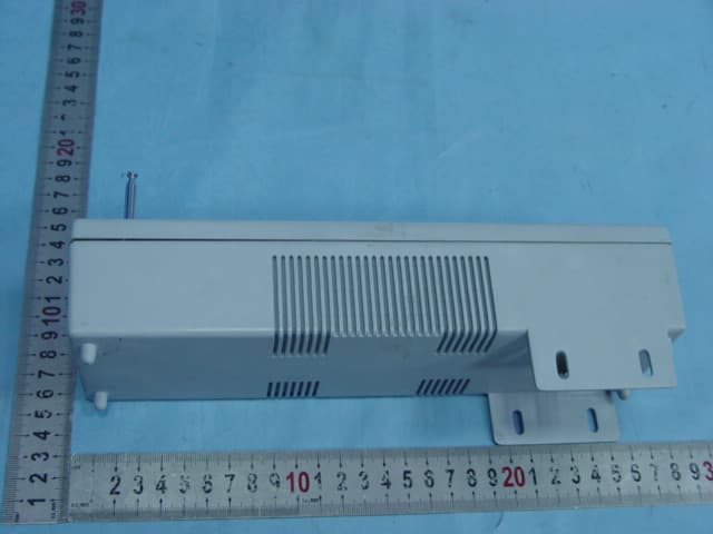
Click to zoom
Application Details
- Equipment Class
- DSC - Part 15 Security/Remote Control Transmitter
- Date of Grant
- Jan 24, 2007
- Application Purpose
- Original Equipment
- Date of Application
- Jan 24, 2007
- Equipment Note
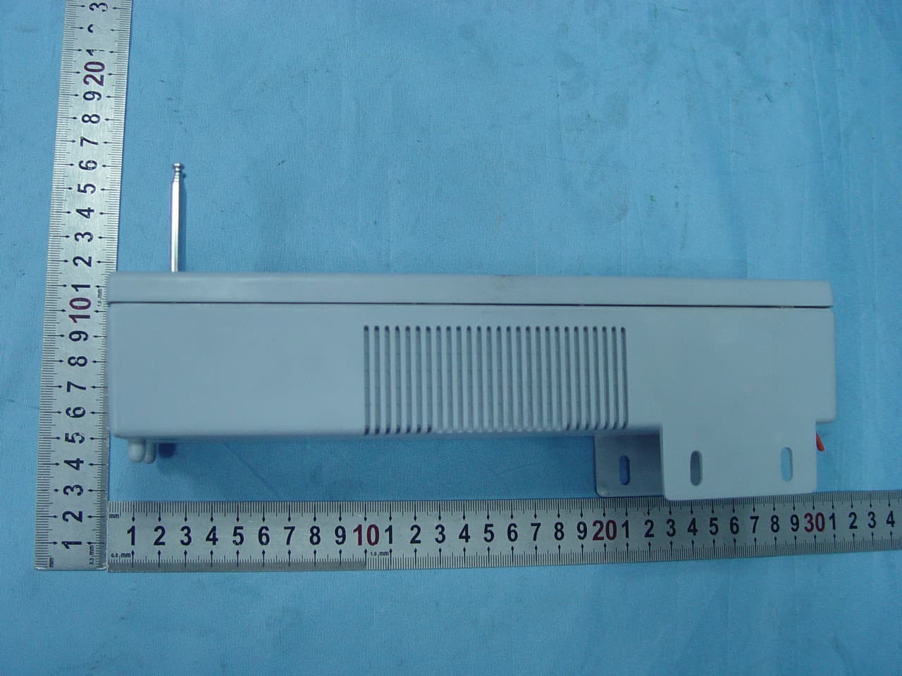
- Radio Frequency (RF) Transmitter
- Frequency Range
- 315.09500000 - 315.09500000
- Company
- Orion Energy Systems Ltd.
- Country
- United States
Documents & Files
Document Text
Text extracted from the exhibit documents filed with the FCC. Open a document above to read the original.
Users Manual
INSTALLATION AND OPERATION INSTRUCTION WTRA-4C RADIO FREQUENCY (RF) TRANSMITTER Orion Energy Systems WARNING Read this manual completely before the wiring, installation and operation of this device. This device is for in-door use only. Danger with high voltage 120 VAC or 208 to 277 VAC. There are risks of electrical shock if this device is not wired or installed properly. This device must be installed by a qualified personnel. DESCRIPTION WTRA-4C is a radio frequency transmitter which transmits radio frequency signals to Orion Energy Systems WREC-2R receivers to remotely turn lights or other devices on and off or to Orion Energy Systems WREP-4C repeaters so that the repeater will relay the signals either to a WREC-2C receiver or another WREP-4C repeater. It can transmit four (4) “off” signals; individually or its combination at one time; or four (4) “on” signals; individually or its combination at one time, but not “on” and “off” signals combination. The duration for each transmission is one second. INSTALLATION AC power supply connection: Warning: Turn power off before you connect this device to your power supply. Make sure your power supply voltage matches the transmitter power supply requirements: 120 VAC or 208 to 277 VAC. For power supply 120 VAC, connect the white wire to neutral and the black wire to the line, leave the red wire alone and cover its end with wire nut. Failure to terminate the unused wire presents a shock hazard. For 208 to 277, connect the white wire to either the neutral or line and connect the red wire to the other line, leave the black wire alone and cover its end with wire nut. Failure to terminate the unused wire presents a shock hazard. Control Wire Connection: There are nine (9) control wire terminals on the printed circuit board (PCB): GND, K1 to K8. Those are dry contacts. See FIGURE 1 WTRA-4C RF TRANSMITTER PCB BOARD LAYOUT for location. Use 24 AWG or larger wires rate 24V or greater to connect the terminals to external relays or control devices. The connection of GND with K1 to K4 forms four (4) “off” signals and GND with K5 to K8 forms four (4) “on” signals. GND, K1 and GND, K5 forms a pair of “off” and “on” signal. So does GND, K2 and GND, K6; GND, K3 and GND, K7; GND, K4 and GND, K8. You can use from one to four pairs according to your needs. Coding: 1 There is a J1 jumper socket on the transmitter printed circuit board as shown in FIGURE 1 WTRA-4C RF TRANSMITTER PCB BOARD LAYOUT. This is the transmitter address. FIGURE 1 WTRA-4C RF TRANSMITTER PCB BOARD LAYOUT You use one jumper to jump the pins high (H) and its central pin, or another jumper to jump the pins Low (L) and its central pin. Any jumper configuration forms address including no jumpers installed on the jumper socket and different jumper configuration forms different address. For example if you jump 4H and its central pin 4, 1L and its central pin 1, it forms address. In order for the transmitter to communicate with WREC- 2R receiver, you need to code the receiver address exactly the same. Otherwise the receiver can not receive the control signal. For details on how to code the receiver address, please refer to Installation and Operation Instruction WREC-2R Radio Frequency (RF) Receiver Orion Energy Systems In order for the transmitter to communicate with WREP-4C repeater, the receiving jumper socket J1 (receiving address) on the repeater PCB board needs to be coded exactly the same. For details on how to code the repeater, please refer to Installation and Operation Instruction WREP-4C Radio Frequency (RF) Repeater Orion Energy Systems OPERATION Warning: Make sure your power supply voltage matches the transmitter power supply requirements: 120 VAC or 208 to 277 VAC. Otherwise there is electrical shock hazard. After the transmitter’s power supply is properly wired and its voltage matches the line power voltage, the control wires are connected with external relays or control devices and the transmitter, receiver or repeater addresses are properly coded, turn the transmitter’s 2 power on. When GND and K1 are connected through an external relay or control device, the transmitter transmits the “off” signal to the receivers or repeaters which have the same receiving code. The same for any other off or on signals. Remember no “off” and “on” signal combination can be transmitted. Transmitter transmits the signal one (1) second only no matter how long the external relay or device connects the terminals. It can transmit the signal again only after the external relay or control devices disconnect the terminals. TROUBLESHOOTING The receivers or repeater can not receive the signal: • Check if there is power to the transmitter. • Check if the light LED 2 light is on. If it is not, it means no power to the transmitter. • Check if the transmission light LED 1 is flashing while the signal is transmitted. If not, the transmitter does not work. • Check if the transmitter address matches the receiver addres or the repeater receiving address. • Check if the jumpers are installed properly. • Check if the receiver or the repeater is too far away from the transmitter. See TCHNICAL DATA for details. • Check if there are big obstacles between the transmitter and receiver or the repeaters. If there are, either re-locate the transmitter or install more repeaters to get the signal around the obstacles. TECHNICAL DATA Power Supply: 120 VAC or 208 to 277 VAC. Antenna: Enclosed. Frequency: 315 MHz Transmission Power: 6 mV/m at 3 meter Transmission range: 300 meter at free field Modulation: ASK Number of Codes Transmitted: four (4) pair (4 off signals and 4 on signals) Operation Temperature: -20 o C to 60 o C (-4 o F to 140 o F) Certification: FCC compliance This device complies with Part 15 of the FCC Rules. If this device is operated in compliance with the following requirements, it can be operated without notification and free of charge in the area of the United States of America. 3 Warning: Changes or modifications mad…
Text truncated - open the document above for the full version.
Block Diagram
Wtra-4c-v1.1.sch-1 mon apr 08.08:54:04.2006 Power Supply Fuse Transient voltage suppression Transformer Rectification Voltage stabilization (12V) Power supply indicating light Voltage stabilization (5V) Address through jumpers Pt2262 encoder (For transmission) RF modulator and amplifier Key combination logic circuit Opto-isolator Transmitting antenna
ID Label/Location Info
FCC MARKING/LABEL FOR PART15 30mm Radio Frequency(RF) Transmitter FCC ID: UTVWTRA4CTX This device complies with Part 15 of the FCC Rules. Operation is subject to the following two conditions: (1)This device may not cause harmful interference, and(2)This device must accept any interference received, including interference that may cause undesired operation. Changes or modifications not expressly approved by the party responsible for compliance could void the user’s authority to operate the equipmen Orion Energy Systems Ltd. Model No.: WTRA-4C Operation Frequency: 315MHz 30mm
Operational Description
Transmitter Configuration: Transmitter has five modules. Key input, MCU, Opto-isolator, key combination logic circuit, PT226 encoding. RF modulator and amplifier, and power supply. Operation Principle: 1) MCU scans key input 2) MCU process the key input 3) Combination logic circuit to form the data according to the input from MCU. send the data to PT2262 for encoding. After PT226's encoding, the waveform is modulated, amplified and transmitted through the antenna. 4) Power supply to provide the power for each module. Power Supply Address through jumpers Pt2262 encoder Key combination logic circuit Opto-isolator Transmitting antenna
Schematics
12345678 A B C D 87654321 D C B A Title NumberRevisionSize A3 Date:13-Nov-2006Sheet of File:Drawn By: 1 2 3 4 BR 2W10 C6 220uF/16V 1 2 3 POWER AC120V-277V C7 1000uF/50V I N 1 G N D 2 O U T 3 IC5 78012 VCC+12V C4 104 C5 104 TRANS EI35 FUSE 1A/250V RC 1.5M R10 10K VCC+12v Q3 M6 LED1 LED R9 6.2K R5 10K R6 10K R7 10K R8 10K K1 K2 K3 K4 K5 K6 K7 K8 D1 1N4148 D2 1N4148 D3 1N4148 D4 1N4148 D5 1N4148 D6 1N4148 D7 1N4148 D8 1N4148 12345678 J1 A 0 1 A 1 2 A 2 3 A 3 4 A 4 5 A 5 6 D 5 7 D 4 8 V S S 9 D 3 1 0 D 2 1 1 D 1 1 2 D 0 1 3 T E 1 4 O S C 2 1 5 O S C 1 1 6 D O U T 1 7 V C C 1 8 U1 PT2262 R12 10K VDD RV1 5D471 RV2 5D241 R13 10K OP1OP2OP3OP4OP5OP6OP7OP8 VDD K 1 K 2 K 3 K 4 K 5 K 6 K 7 K 8 P2.2 1 P2.3 2 RST 3 RXD/P3.0 4 TXD/P3.1 5 XTAL2 6 XTAL1 7 INT0/P3.2 8 INT1/P3.3 9 ECI/T0/P3.4 10 PWM1/PCA1/T1/P3.5 11 PWM3/PCA3/P2.4 12 P2.5 13 VSS 14 P2.6 15 P2.7 16 P3.7/PCA0/PWM0 17 P1.0/ADC0 18 P1.1/ADC1 19 P1.2/ADC2 20 P1.3/ADC3 21 P1.4/SS/ADC4 22 P1.5/MOSI/ADC5 23 P1.6/MISO/ADC6 24 P1.7/SCLK/ADC7 25 P2.0/PCA2/PWM2 26 P2.1 27 VDD 28 U2 STC12C5404_SOP28 1 2 3 IN1A 1 2 3 IN1B 1 2 3 IN1C R14 1K R15 1K R16 1K R17 1K R18 1K R19 1K R20 1K R21 1K P2_0 P2_1 P2_2 P2_3 P2_4 P2_5 P2_6 P2_7 P 2 _ 0 P 2 _ 1 P 2 _ 2 P 2 _ 3 P 2 _ 4 P 2 _ 5 P 2 _ 6 P 2 _ 7 R22 1K R23 1K R24 1K R25 1K R26 1K R27 1K R28 1K R29 1K VCC+5V 1 2 3 4 J2 VCC+5V I N 1 G N D 2 O U T 3 U3 78L05 C9 220uF/16V C8 104 VCC+5V K1_1 K1_7 K1_6 K1_5 K1_4 K1_3 K1_2 K1_8 C10 104 XTAL1 XTAL2 C1 100PF R3 18K R2 47K ANT ANTENNA Q1 8050 3 1 2 Y1 R315 Q2 RF VCC+12V C2 L1 4.5*7.5T L2 4.5*4.5T C20 5.6PF C21 L4 0R L3 47nH C22 15P LED2 LED R4 4.7K VCC+12V Wtra-4c-v1.1.sch-1 mon apr 08.08:54:04.2006
Test Report
Page 1 of 33 FCC ID: UTVWTRA4CTX ACCURATE TECHNOLOGY CO. LTD REPORT NO. ATE20062808 APPLICATION CERTIFICATION On Behalf of Orion Energy Systems Ltd. Radio Frequency (RF) Transmitter Model No.: WTRA-4C FCC ID: UTVWTRA4CTX Prepared for : Orion Energy Systems Ltd. Address : 1204 Pilgrim Road, Plymouth, WI 53073, USA Prepared by : ACCURATE TECHNOLOGY CO. LTD Address : F1, Bldg. A, Changyuan New Material Port, Keyuan Rd. Science & Industry Park, Nanshan, Shenzhen, Guangdong P.R. China Tel: (0755) 26503290 Fax: (0755) 26503396 Report Number : ATE20062808 Date of Test : January 19, 2007 Date of Report : January 22, 2007 Page 2 of 33 FCC ID: UTVWTRA4CTX ACCURATE TECHNOLOGY CO. LTD REPORT NO. ATE20062808 TABLE OF CONTENTS Description Page Test Report Certification 1. GENERAL INFORMATION.......................................................................................................... 4 1.1. Description of Device (EUT)....................................................................................................................4 1.2. Description of Test Facility......................................................................................................................4 1.3. Measurement Uncertainty.........................................................................................................................4 2. MEASURING DEVICE AND TEST EQUIPMENT..................................................................... 5 3. CONDUCTED EMISSION FOR FCC PART 15 SECTION 15.207(A)...................................... 6 3.1. Block Diagram of Test Setup....................................................................................................................6 3.2. The Emission Limit For Section 15.207(a)..............................................................................................6 3.3. EUT Configuration on Measurement.......................................................................................................7 3.4. Operating Condition of EUT....................................................................................................................7 3.5. Test Procedure..........................................................................................................................................7 3.6. Power Line Conducted Emission Measurement Results..........................................................................8 4. THE FIELD STRENGTH OF RADIATION EMISSION............................................................ 9 4.1. Block Diagram of Test Setup....................................................................................................................9 4.2. The Field Strength of Radiation Emission Measurement Limits..............................................................9 4.3. Configuration of EUT on Measurement.................................................................................................10 4.4. Operating Condition of EUT..................................................................................................................10 4.5. Test Procedure........................................................................................................................................10 4.6. The Field Strength of Radiation Emission Measurement Results..........................................................11 5. 20DB OCCUPIED BANDWIDTH................................................................................................ 13 5.1. Block Diagram of Test Setup..................................................................................................................13 5.2. The Bandwidth of Emission Limit According To FCC Part 15 Section 15.231(c)................................13 5.3. EUT Configuration on Measurement.....................................................................................................14 5.4. Operating Condition of EUT..................................................................................................................14 5.5. Test Procedure........................................................................................................................................14 5.6. Measurement Result...............................................................................................................................15 6. RELEASE TIME MEASUREMENT............................................................................................ 16 6.1. Block Diagram of Test Setup..................................................................................................................16 6.2. Release Time Measurement According To FCC Part 15 Section 15.231(a)..........................................16 6.3. EUT Configuration on Measurement.....................................................................................................17 6.4. Operating Condition of EUT..................................................................................................................17 6.5. Test Procedure........................................................................................................................................17 6.6. Measurement Result...............................................................................................................................18 7. AVERAGE FACTOR MEASUREMENT.................................................................................... 19 7.1. Block Diagram of Test Setup..................................................................................................................19 7.2. Average factor Measurement..................................................................................................................19 7.3. EUT Configuration on Measurement.....................................................................................................20 7.4. Operating Condition of EUT....................................................…
Text truncated - open the document above for the full version.
Contact Information
Applicant
Jun Wang(Director)
Test Firm
Accurate Technology Co., Ltd.Sean Liu
Technical Specifications
| # | Rule Parts | Frequency Range | Power Output |
|---|---|---|---|
| 1 | 15.231 | 315.095 MHz - 315.095 MHz | - |
Other Applications from Orion Energy Systems Ltd.
UTVWREP4CRT
Jan 18, 2007Radio Frequency(RF) Repeater
Equipment Class
DSR - Part 15 Remote Control/Security Device Transceiver