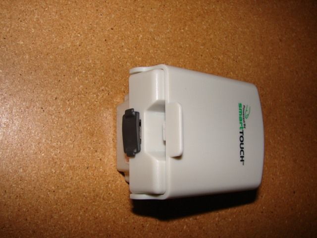
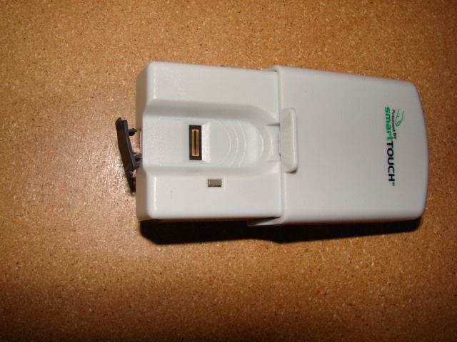
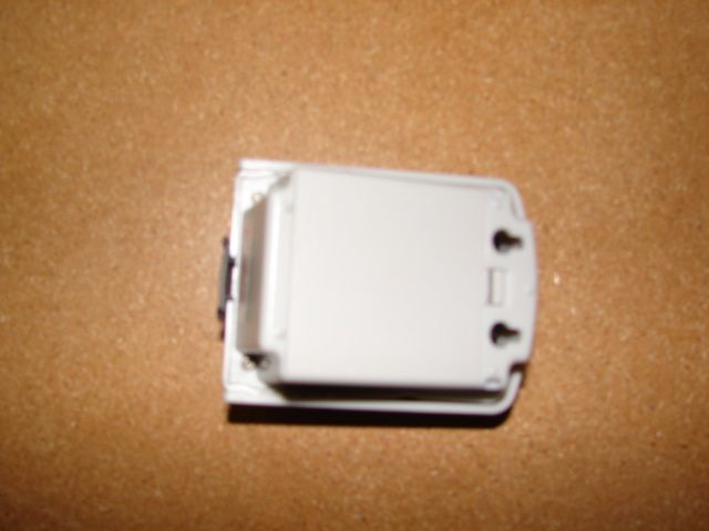
UULGDOB1BIOMETRICALLY CONTROLLED GARAGE OPENER
Biometrx Inc.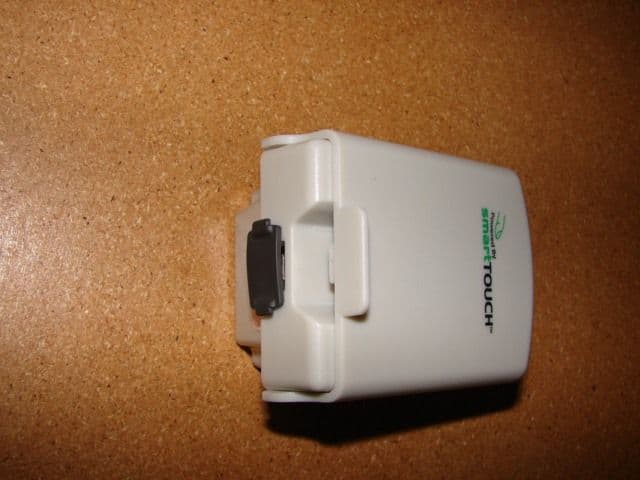
Click to zoom
Application Details
- Equipment Class
- DSC - Part 15 Security/Remote Control Transmitter
- Date of Grant
- Dec 20, 2006
- Application Purpose
- Original Equipment
- Date of Application
- Dec 20, 2006
- Equipment Note
- BIOMETRICALLY CONTROLLED GARAGE OPENER
- Frequency Range
- 433.42000000 - 434.42000000
- Company
- Biometrx Inc.
- Country
- United States
Documents & Files


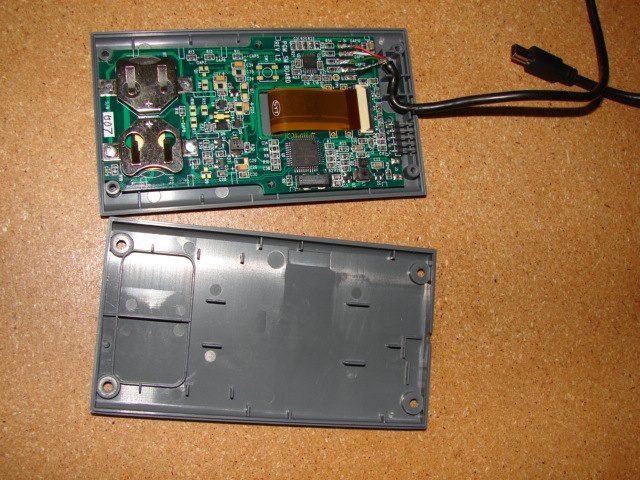
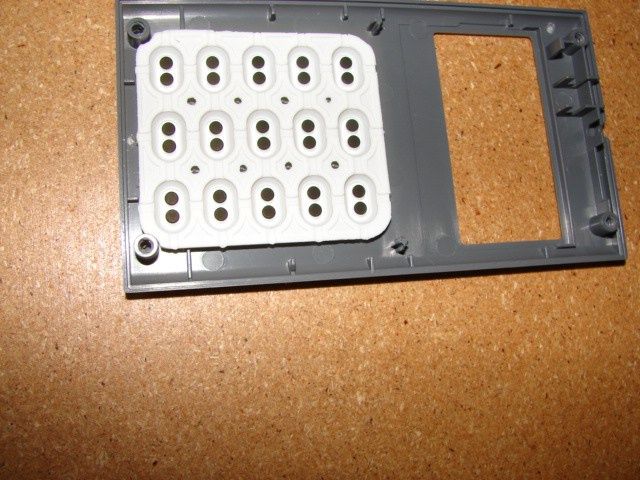
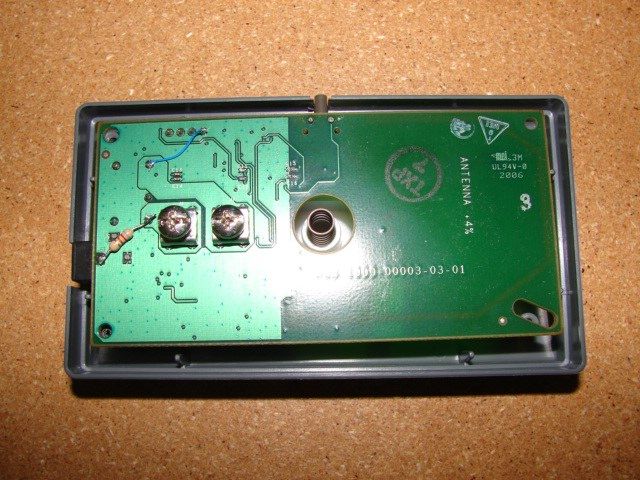
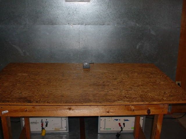


Document Text
Text extracted from the exhibit documents filed with the FCC. Open a document above to read the original.
Users Manual
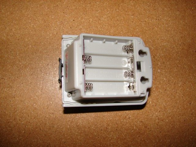
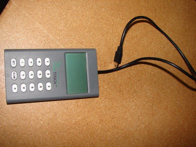
smartTOUCH ™ Finger Activated Garage Door Opener USER MANUAL Included in Box: • Programmer • Relay • Sensor Unit • Power Supply • 2 Paper Drill templates • 4 Mounting Screws • Cat-3 2-Wire Cable (20 ft.) • 2 locking brackets Hardware Required for Installation: • (4) #6 self taping screws • 2 drill templates • Philips head screwdriver (not supplied) • 20 feet of installation cable included WA R N I N G To prevent possible serious injury or death from a moving gate or garage door: - Always keep remote controls out of reach of children. Never permit children to operate, or play with remote control transmitters. - Activate gate or door only when it can be seen clearly, is properly adjusted, and there are no obstructions to door travel. - Always keep gate or garage door in sight until completely closed. Never permit anyone to cross path of moving gate or door. Step 1 Pairing Relay to Sensor Unit RECOMMENDED Perform on flat surface before mounting. A) Remove the programmer, relay and sensor unit from box B) Connect relay unit to power supply C) Remove battery door on sensor unit - Install 4 AAA batteries (not included) D) Connect programmer to sensor unit (powers up only when connected to sensor) E) Open cover of sensor unit - Green LED light will display on both sensor and relay units F) Press OK on programmer Note: Ensure sensor unit and relay are at least 3 feet apart G) Enter set–up mode - Follow prompts on LCD display [Observe relay for required feedback] - Pair sensor unit to relay Once pairing is complete, you will be prompted to define administrator. Step 2 Enrollment Define Administrators A) Connect programmer to sensor unit B) Lift sensor unit cover. Sensor unit will display green LED light C) Press “OK” on programmer Note: 3 successful swipes are required to complete enrollment. - Follow programmer prompts to enroll administrator - Programmer will advise “looking for image” and “processing image” after finger swiped - “Processing image” indicates 3 successful swipes accepted D) When prompted, please choose a 4 digit pin number - Press CAN to go back to previous page As an administrator, you can add or delete other administrators or access users. Follow enrollment process to add and delete users as needed. If during enrollment programmer freezes/powers off - disconnect programmer, close sensor unit cover, reconnect programmer, open sensor unit cover and proceed to enrollment Step 3 Test Units Once administrator is enrolled, proceed to test units A) Close sensor unit cover B) Disconnect programmer from sensor unit C) Open sensor unit cover D) Swipe previously accepted finger again - Relay will flash green and click E) Remove power supply from relay unit and proceed to installation Note: If test fails (relay unit doesn’t flash and click simultaneously) proceed to Factory Reset and pair units again. How to Swipe Finger Note A solid green LED indicates sensor unit is ready to accept finger swipe Swipe the pad of your finger firmly over the sensor in slow and steady motion. Sensor unit provides feedback if swipe is accepted. Flashing red LED swipe indicates unsuccessful read. Green LED blinks twice, turns off and returns to solid state if swipe is successful. NOTE: When programmer is connected during unit administration LCD display will indicate “bad swipe”. Reasons for unsuccessful swipe: o Wrong finger swiped o Finger swiped too fast o Finger swiped too slow o Inaccurate finger placement Select a mounting location. Step 5 Install Sensor Unit A) Select mounting location for sensor unit outside of garage B) Test to ensure sensor unit is within relay range C) Tape sensor unit drill template to the desired location D) Mark center of 2 mounting eyelets on wall E) Install the two mounting screws on the wall where marked F) Leave 1 /10 inch gap between screw and wall G) Insert locking brackets to first line (with tabs facing front of sensor unit) H) Mount sensor on wall, aligning mounting screw heads with mounting eyelets I) Slide sensor unit down on to screws and push in locking brackets till flush Factory Reset Sensor Unit - Connect programmer to sensor unit - Lift sensor unit cover - Swipe enrolled administrator finger to access administrator menu - Select “5” – system --> Select “3” – factory reset --> Press “1” – to accept factory default reset - Press “1” – to accept default - Programmer will indicate programmer factory default accepted - Close sensor unit cover - Remove programmer from sensor unit Relay Unit - Press and hold learn button - LED light will turn off - Continue holding learn button down until light turns on again - Disconnect power from relay unit for 10 seconds and then reconnect - Relay unit successfully reset Note: In order to use the sensor and relay unit, you must pair again. Note Can only be performed by administrative user mini USB port LED display swipe sensor sensor unit cover channel guide Sensor Unit Trouble Shooting Guide Step 4 mounting eyelets locking tab battery door Install Relay Unit back top Relay Unit front t o p righ t learn switch push button power port back wire channel mounting eyelets terminal screws Programmer 123 456 789 0 OKCAN LCD display keypad mini-USB cable Power Supply 1 2 3 4 5 6 7 8 9 0 OKCAN Follow Me... Note We recommend you disconnect power to opener before performing this step. -Tape relay drill template to mounting surface -Mark center of 2 mounting eyelets on wall -Install screws into walls at marked points. Leave 1/10th inch gap between screw head and wall Replacing Existing Switch Remove existing wall switch and connect 2 existing wires to terminal screws on back of relay unit -Loosen terminal screws on back of relay unit. 2 wires must be stripped approx. 3/4 inches -Bend end of wires to hook around screw heads -Once wires catch around screws, tighten screws and ensure wires are secure. *DO NOT ALLOW WIRES TO TOUCH OPPOSITE SCREW TERMINAL -Mount relay unit on wall by aligning mounting screws with mounting eyelets Not Replacing Exist…
Text truncated - open the document above for the full version.
Cover Letter(s)
500 North Broadway Suite 204 Jericho, NY 11753 (tel) 516-937-2828 (fax) 516-937-2880 www.biometrx.net Federal Communications Commission Authorization and Evaluation Division Confidentiality Request regarding application for certification of FCC ID: UULGDOB1 Pursuant to Sections 0.457 and 0.459 of the Commission’s Rules, we hereby request confidential treatment of information accompanying this application as outlined below: Exhibit Type File Name Schematics apb_rev_01a.pdf Programmer_schematic.pdf Relay_bd_09.pdf Sensor_2510_Sch_Rev05.pdf Operational Description Operational Description.doc Block Diagram HW Block Diagram.pdf The above materials contain trade secrets and proprietary information not customarily released to the public. The public disclosure of these materials may be harmful to the applicant and provide unjustified benefits to its competitors. The applicant understands that pursuant to Section 0.457 of the Rules, disclosure of this application and all accompanying documentation will not be made before the date of the Grant for this application. Sincerely, Lorraine Yarde
ID Label/Location Info
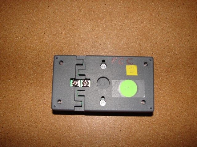
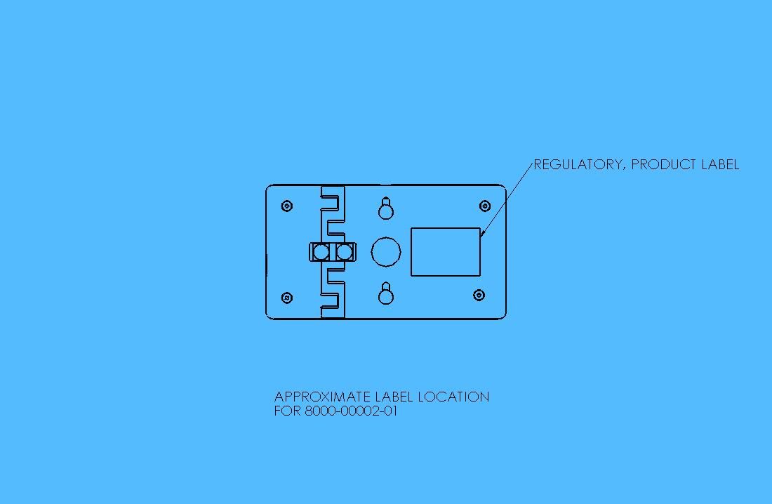
GDO-B1-PRO S/N:12345678 3V Lithium - CR2032 GDO-B1-REL S/N:12345678 5VDC 1 AMP GDO-B1 S/N:12345678 GDO-B1-SEN S/N:12345678 4AAA 1.5V Alkaline Batteries FCC ID: UULGDOB1
Test Report
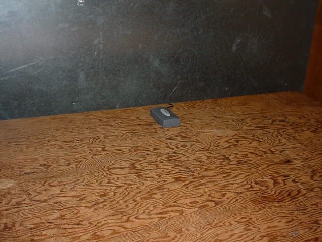
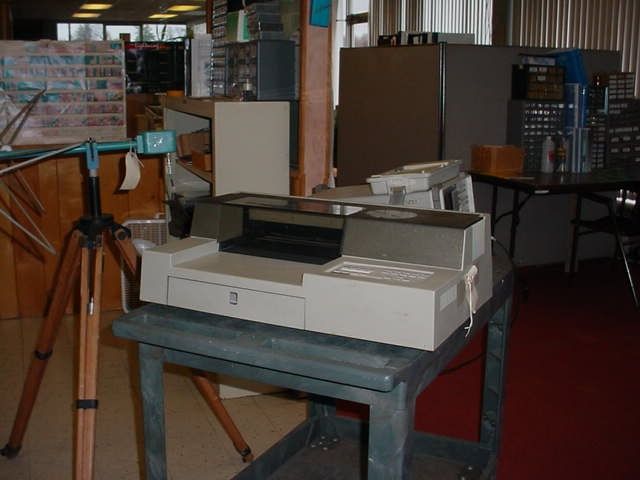
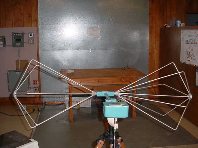
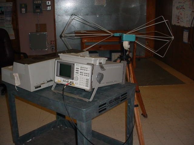
DIVERSIFIED T.E.S.T. TECHNOLOGIES, INC. – TEST REPORT Biometrx Project Number: SmartTOUCH Finger Activated Garage Door Opener 5941 This report shall not be reproduced, except in full, without the written approval of DTT, Inc. 1 of 12 October 9, 2006 Lorraine Yarde Biometrx 500 North Broadway Suite 204 Jericho, NY 11753 Dear Ms.Yarde: Enclosed is the test report for the Biometrx SmartTOUCH Finger Activated Garage Door Opener tested at our facility, located at 556 Route 222 in Groton, NY. This facility is on file with the Federal Communications Commission (FCC) per 47 CFR 2.948 (Site File Number 31040/SIT) and is NVLAP accredited. We have completed our testing of Radiated and Conducted Emissions to the FCC per CFR 47 Part 15 Class C for Unintentional Radiators. Thank you for selecting Diversified T.E.S.T. Technologies, Inc. for your testing needs. We look forward to working with you on future projects. Should you have any questions or concerns regarding this report, contact me at 607-898-4218. Please feel free to visit our website at www.dttlab.com. Sincerely, Henry McCoy Technical Associate DIVERSIFIED T.E.S.T. TECHNOLOGIES, INC. – TEST REPORT Biometrx SmartTOUCH Finger Activated Garage Door Opener Project Number: 5941 This report shall not be reproduced, except in full, without the written approval of DTT, Inc. 2 of 12 Test Report – Table of Contents TEST INFORMATION.................................................................................................... 3 TEST REGULATIONS.................................................................................................... 4 EQUIPMENT UNDER TEST (EUT) TESTING OPERATION MODE.................... 5 TEST RESULTS............................................................................................................... 6 EMISSIONS TESTING CONDITIONS......................................................................... 7 RADIATED EMISSIONS............................................................................................................... 7 CONDUCTED EMISSIONS............................................................................................................ 8 RADIATED EMISSIONS TEST DATA........................................................................................... 9 CONDUCTED EMISSIONS TEST DATA..................................................................................... 10 CERTIFICATE OF CONFORMITY........................................................................... 12 DIVERSIFIED T.E.S.T. TECHNOLOGIES, INC. – TEST REPORT Biometrx Project Number: SmartTOUCH Finger Activated Garage Door Opener 5941 This report shall not be reproduced, except in full, without the written approval of DTT, Inc. 3 of 12 T T e e s s t t I I n n f f o o r r m m a a t t i i o o n n Laboratory Diversified TEST Technologies, Inc. 556 Route 222 – PO Box 8 Groton, NY 13073 607-898-4218 Manufacturer Biometrx 500 North Broadway Suite 204 Jericho, NY 11753 Report Issue Date: October 9, 2006 Report Number: 5941-092206(Edition 1) Project Number: 5941 Date Received: September 13, 2006 Date Tested: September 13, 14, 15, and 21, 2006 Product: SmartTOUCH Finger Activated Garage Door Opener Traceability: Reference standards of measurement have been calibrated by a competent body using standards traceable to NIST. The testing performed by Diversified TEST Technologies, Inc. has shown that the product referenced above complies with the electromagnetic compatibility requirements according to the FCC per CFR 47 Part 15. The results in this test report apply only to the SmartTOUCH Finger Activated Garage Door Opener . It is the responsibility of the manufacturer to ensure that the product identification and labeling are in compliance with the applicable standards requirements. The manufacturer is also responsible for ensuring that additional units are manufactured with identical mechanical and electrical characteristics. The equipment listed above conforms to the specified requirements of the test standards listed in the Test Regulations section of this report. Complied by: Signature: Date: 10-12-06 Henry McCoy Technical Associate Reviewed by: Signature: _____________________________ Date: 10-12-06 Annelle Frierson Vice President DIVERSIFIED T.E.S.T. TECHNOLOGIES, INC. – TEST REPORT Biometrx SmartTOUCH Finger Activated Garage Door Opener Project Number: 5941 This report shall not be reproduced, except in full, without the written approval of DTT, Inc. 4 of 12 T T e e s s t t R R e e g g u u l l a a t t i i o o n n s s The tests were performed according to the following standards: FCC Part 15 Class C Certification Verification DIVERSIFIED T.E.S.T. TECHNOLOGIES, INC. – TEST REPORT Biometrx SmartTOUCH Finger Activated Garage Door Opener Project Number: 5941 This report shall not be reproduced, except in full, without the written approval of DTT, Inc. 5 of 12 E E q q u u i i p p m m e e n n t t U U n n d d e e r r T T e e s s t t ( ( E E U U T T ) ) T T e e s s t t i i n n g g O O p p e e r r a a t t i i o o n n M M o o d d e e The EUT was operated under the following conditions during testing: Standby Normal Operating Mode Practice Operation Description / Configuration of the EUT: The SmartTOUCH Garage Door Opener uses an advanced finger activated technology, that provides secure, and personalized access to your home through the garage. The EUT was powered with 120VAC, 60Hz and 4 AA Batteries during the collection of data included within this report. Rationale for EUT setup / configuration: ANSI C63.4 Modifications: None Deviations from test method: None DIVERSIFIED T.E.S.T. TECHNOLOGIES, INC. – TEST REPORT Biometrx SmartTOUCH Finger Activated Garage Door Opener Project Number: 5941 This report shall not be reproduced, except in full, without the written approval of DTT, Inc. 6 of 12 T T e e s s t t R R e e s s u u l l t t s s Radiated Emissions 30 MHz – 1000 MHz The requirements are MET NOT MET Conducted Emissions 0.15 MHz – 30…
Text truncated - open the document above for the full version.
Contact Information
Applicant
Lorraine Yarde(Chief Operating Officer)
Test Firm
Diversified T.E.S.T. TechnologiesThomas Sims
Technical Specifications
| # | Rule Parts | Frequency Range | Power Output |
|---|---|---|---|
| 1 | 15.231 | 433.42 MHz - 434.42 MHz | - |