FCCID.CO- FCC ID Database
HomeCompaniesEquipment ClassesSearch

© 2026 FCC ID Database. All rights reserved.

AboutContactData sourced from FCC public records
  1. Home/
  2. Elinchrom SA/
  3. UV7EL-SKYPORT

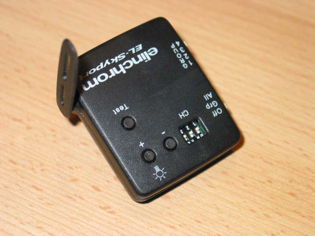
UV7EL-SKYPORTWireless flash triggering system

Elinchrom SA
Wireless flash triggering system - FCC ID UV7EL-SKYPORT - Elinchrom SA
Click to zoom

Application Details

Equipment Class
DTS - Digital Transmission System
Date of Grant
Mar 13, 2007
Application Purpose
Original Equipment
Date of Application
Jan 16, 2007
Equipment Note
Wireless flash triggering system
Frequency Range
2448.00000000 - 2475.00000000
Company
Elinchrom SA
Country
Switzerland

Documents & Files

Select a file to view
Users Manual

↗
↗
↗
↗

Cover Letter(s)

↗
↗
↗

External Photos

↗

ID Label/Location Info

↗
↗

Internal Photos

↗

Operational Description

↗

Test Report

↗

Test Setup Photos

↗

Document Text

Text extracted from the exhibit documents filed with the FCC. Open a document above to read the original.

Users Manual

Instructions for use Istruzioni per l’uso Инструкция по эксплуатации Instrucciones para el uso Universal Receiver EL-Skyport Universal Receiver 19352 C o n t e n t s : Features 2 Battery Charging 3 Operating Instructions 4 Operating Modes 4 Frequency Channel 5 Trigger Group Settings 5 Integrated SYNC Socket 6 Elinchrom RX Features 6 EL-Skyport Modules 7 Troubleshooting 8 CE Statements 8 FCC Compliance and Advisory Statement 9 Disposal and recycling 9 English English 1 - 9 Français 10 - 18 Deutsch 19 - 27 Italiano 28 - 36 Русский 37 - 45 Español 46 - 54 Gurantee 55 - 56 Battery Charging The internal Li-Ion battery is rechargeable. Use only the EL-Skyport Wall-Adapter Charger. 1. Switch OFF the unit for fastest charging time. 2. Connect the EL-Skyport charger to the Universal charge socket and connect to mains supply 3. When the Status LED is ON, charging is in progress 4. When the Status LED is OFF, the Battery is fully recharged ! CAUTION: • Use only the original Elinchrom EL-Skyport Wall-Adapter Charger (19355 EU) to charge the battery • Do not open the housing to replace the battery • Switch OFF when the Universal Receiver is not in use to save Battery power. Note: Stand-By mode does not completely switch off the unit. Status LED OFF Universal Receiver • is switched OFF or • when Charger is plugged-in, the Battery is fully recharged or • if switched ON, the unit is in Stand-By mode. (Switch off and on to reawaken) ON Universal Receiver charges. Flashing Universal Receiver is in operating mode EL-Skyport Universal Receiver 19352 Operating instructions : 2.4 GHz digital wireless Universal Receiver for flash triggering Features EL-Skyport flash trigger is designed with the latest 2.4 GHz Digital Wireless Technology. • Triggers all flash brands with SYNC socket • Up to 1/1000s shutter speed • 4 selectable trigger groups • 8 frequency channels • 40 Bit security encryption • Up to 50 m range indoors • Up to 120 m range outdoors • Internal rechargeable Battery lasts up to 30 hours • Integrated Quick Charger circuit • 3.5mm SYNC-socket for all common flash units • Auto-Standby function after 4 hours You will appreciate the convenience of this professional, and powerful wireless device. Note: Shutter speed and distance range is influenced by reflections (from ceilings, walls, floor, furniture and other equipment) and interference from other 2.4 GHz electronic equipment. For best performance the Transmitter and Receiver antenna should have direct sight, without any walls or objects in-between. 2 3 Fig. 1 3.5mm SYNC socket Operating Instructions 1. Connect the SYNC cable to the EL-Skyport SYNC socket and the flash unit SYNC socket. Use included SYNC cable. 2. Check the correct Group and Channel setting for the Transmitter and Universal Receiver. 3. Switch ON the EL-Skyport Universal Receiver and Transmitter 4. Switch flash unit ON and press “TEST” push button on EL-Skyport Transmitter for a Test flash. Operating Modes 1. Battery mode: Charge LED flashes when switched ON. If not used for 4 hours, the unit will switch to Stand-By Mode (switch Receiver OFF and ON to return to normal mode) 2. Supply mode: With Wall-Adapter Charger plugged in for long term fixed operation Note: If the EL-Skyport Receiver is used whilst charging (in Supply Mode), the Universal Receiver will not change to Stand-By mode. Frequency channel selector Flexible swivel Antenna 360 ̊ Charge socket for EL-Skyport Wall Charger only GROUP switch ON/OFF switch Status LED (green) Frequency Channel Note: Transmitter and the corresponding RX Transceivers or Universal Receivers must have the same frequency channel setting ! Frequency Channel Slide Button configuration Trigger Frequency / Mhz Remote Frequency / Mhz 123 1 (default)OffOffOff24562448 2OnOffOff24582450 3OffOnOff24602452 4On OnOff24622454 5OffOffOn24692461 6OnOffOn24712463 7OffOnOn24732465 8OnOnOn24752467 Note: After changing the frequency, switch Receiver OFF and ON again to activate the new settings. Trigger Group Settings The EL-Skyport Transmitter triggers the Universal Receiver in following modes: 1. Groups(1 to 4) sets and triggers flash units in different “Groups” è only Flash Units with the selected Group are triggerd by the Transmitter (Group setting must correspond between Transmitter and Receiver) 2. ALL Transmitter is set to ALL è The Transmitter triggers all EL-Skyport Receivers 4 5 Integrated SYNC Socket The integrated 3.5mm Mono Jack socket is for direct connection to all flash brands with max. 50 V SYNC voltage and a max. peak current of 0.5 Amps. EL-Skyport Features All EL-RX flash units accept computer operation. Use 19354, 19353 and the EL-Skyport PC/MAC Software to access EXTRA features: 1. Automatic PnP (Plug and Play) detection. The software automatically adds connected RX units to the unit list. 2. Flash Stand-By Mode: Activates and deactivates the flash trigger via EL-Skyport Software 3. Adjustable independent Flash Delay triggering for flash sequencing, between 5 milliseconds and 16 seconds 4. The EL-Skyport software offers many additional features. For further information please check www.elinchrom.com EL-Skyport Modules EL-Skyport Transmitter 19351 • Universal Transmitter triggers all EL-Skyport Receivers via the Camera Hot-shoe or SYNC cable! EL-Skyport Transceiver RX 19353 • The Transceiver is only for Elinchrom RX units. This module operates all RX features with the EL-Skyport / ERS- software and triggers the flash EL-Skyport USB RX 19354 • To operate RX flash units via the computer, the USB module, the Transceiver RX and the EL-Skyport ERS- software is required. USB RX 19354 Transmitter 19351 Transceiver RX 19353 6 7 Troubleshooting Should an error occur, first check the following points: Having this problem?Check the following points: Universal Receiver is not trig- gered by the Transmitter. Mode “All” is selected Ø Check if the Transmitter is switched ON Ø Check battery polarity Ø Check if the Receiver module is connected correctly to the uni…

Text truncated - open the document above for the full version.

Users Manual

Transmitter Instructions for use Istruzioni per l’uso Инструкция по эксплуатации Instrucciones para el uso EL-Skyport Transmitter 19351 C o n t e n t s : Features 2 Battery Installation 3 Hot-shoe connector 3 Operating Instructions 3 Frequency Channel 4 Trigger Modes 5 Integrated SYNC Socket 5 Elinchrom RX Features 5 EL-Skyport Modules 6 Troubleshooting 7 CE Statements 7 FCC Compliance and Advisory Statement 8 Disposal and recycling 8 English 1 - 8 Français 9 - 16 Deutsch 17 - 24 Italiano 25 - 32 Русский 33 - 40 Español 41 - 48 Gurantee 49 - 50 English Hot-shoe with SYNC socket Battery drawer (19373) Battery (19373) Minus pole on top Flexible swivel Antenna 360 ̊ F i g . 1 Battery Installation 1. Pull the battery drawer out carefully 2. Place the Lithium battery, see Fig. 1 for polarity 3. Close the battery drawer ! CAUTION: • Ensure correct polarity / minus pole on top • Use original Elinchrom Lithium Battery only (CR2430 3.0V 19372) • Remove battery if the EL-Skyport Transmitter is not to be used for some time • Never short-circuit battery poles Hot-shoe connector The standard Hot-shoe connector with middle contact synchronisation is designed for all digital and analogue cameras with maximum sync output of 3V (The middle contact is the positive pole). Operating Instructions EL-Skyport Transmitter 19351 Operating instructions : 2.4 GHz digital wireless Flash Trigger Transmitter Features EL-Skyport flash trigger is designed with the latest 2.4 GHz Digital Wireless Technology. • Up to 1/1000s shutter speed • 5 selectable trigger modes • 8 frequency channels • 40 Bit security encryption • Up to 50 m range indoors • Up to 120 m range outdoors • Battery life up to 3 Months • RX-feature buttons (Remote Control) • Test trigger button • Integrated Hot-shoe (middle contact) • SYNC-socket for direct connection You will appreciate the convenience of this professional, and powerful wireless device. Note: Shutter speed and distance range is influenced by reflections (from ceilings, walls, floor, furniture and other equipment) and interference from other 2.4 GHz electronic equipment. For best performance the Transmitter and Receiver antenna should have direct sight, without any walls or objects in between. 2 3 Trigger Modes The EL-Skyport Transmitter can trigger EL-Skyport Receiver modules in the following modes: 1. Off è Unit is OFF 2. Select Grp - Group(1 to 4) è Set switch to Grp. and select Group 1 to 4 è All corresponding EL-Skyport Receivers with the same selected Group (1 to 4) are triggered 3. ALL è Mode switch is set to ALL è All corresponding EL-Skyport Receivers are triggered regardless of which Group is selected. Integrated SYNC Socket The integrated 2.5mm Mono Jack socket is for direct connection to the camera or lens Elinchrom RX Features If the EL-Skyport Transmitter is used with the latest EL-Skyport Transceivers RX, the following EXTRA features are available: Depending upon which Group is selected, The following RX-unit settings can be applied: 1. Power increase in 1/10 f-stops è press push button + to increase the power of selected Group (or ALL) RX-units in 1/10 f-stops 2. Power decrease in 1/10 f-stops è press push button - to reduce the power of selected Group of (or ALL) RX-units in 1/10 f-stops 3. Modelling lamp toggle è press and hold the push button + longer than 2 seconds before release, to toggle modelling lamp of the selected Group of (or ALL) RX-units. Frequency Channel Note: Transmitter and the corresponding Transceivers RX or Universal Receivers must have the same frequency channel setting ! Fig. 2 Flexible swivel Antenna 360 ̊ Flash Test RX feature button Power increase OR modelling lamp toggle RX feature button Power decrease Frequency channel selector MODE switch GROUP switch Frequency Channel Slide Button configurationFrequency / Mhz 123 1 (default)OffOffOff2456 2OnOffOff2458 3OffOnOff2460 4On OnOff2462 5OffOffOn2469 6OnOffOn2471 7OffOnOn2473 8OnOnOn2475 N o t e : After setting, switch Transmitter OFF and ON again to activate the new frequency channel change. 4 5 Troubleshooting Should an error occur, first check the following points: Having this problem?Check the following points: No Flash unit is triggered by the Transmitter Mode “All” is selected Ø Check if the Transmitter is switched ON Ø Check battery polarity Ø Check if the Receiver module is connected correctly to the unit Ø Check if the frequency selector switch is set to the same channel Some Flash units are not trig- gered by the Transmitter Mode “Grp” is selected Ø Check if the Channel selector switch is set to the same Group Ø Reduce distance to any “not working” units TEST flash works, but the camera will not trigger Flash unit Ø Check hot-shoe fitting Ø Choose SYNC cable instead of hot-shoe connection Distance range is too small Ø Reposition the unit Ø Increase the distance to walls and ceilings Ø Position the antenna of Transmitter and Receiver Ø Use an RX extension cable to reduce the distance between modules CE Statements This device has been tested and found to comply with the requirements set up in the council directive on the approximation of the law of member states relating to EMC Directive 89/336/EEC, Low Voltage Directive 73/23/EEC and R&TTE Directive 99/5/EC EL-Skyport Modules EL-Skyport Universal 19352 • Universal Receiver for all makes of Flash having a SYNC socket! EL-Skyport Transceiver RX 19353 • This Transceiver is only for Elinchrom RX units. The module operates all RX features with the EL-Skyport / ERS- software and triggers the flash EL-Skyport USB RX 19354 • To operate RX flash units via computer the USB module should be used in conjunction with the EL-Skyport Transceivers RX and the ERS- software Universal 19352 Transceiver RX 19353 USB RX 19354 6 7 FCC Compliance and Advisory Statement This device complies with Part 15 of the FCC rules. Operation is subject of the following two conditions: 1. this device may not cause harmful interference, and 2. this device must accept any inter…

Text truncated - open the document above for the full version.

Users Manual

Instructions for use Istruzioni per l’uso Инструкция по эксплуатации Instrucciones para el uso Transceiver RX EL-Skyport Transceiver RX 19353 C o n t e n t s : Features 2 Extra RX features with EL-Transmitter 2 Computer Remote control features 3 Operating Instructions 3 Flash Trigger 3 Computer Remote Control 4 Frequency Channel 5 Trigger Group Modes 5 EL-Skyport Features 6 EL-Skyport Modules 7 Troubleshooting 8 CE Statements 8 FCC Compliance and Advisory Statement 9 Disposal and recycling 9 English 1 - 9 Français 10 - 18 Deutsch 19 - 27 Italiano 28 - 36 Русский 37 - 45 Español 46 - 54 Gurantee 55 - 56 English Operating Instructions Flash trigger 1. Plug in the Transceiver RX to your ELINCHROM RX flash unit. 2. Check for the correct Group-Switch setting and the correct Frequency Channel setting on all EL-Skyport modules. 3. Switch the ELINCHROM RX Flash Unit ON. For TEST Press the “TEST” push button on EL-Skyport Transmitter. EL-Skyport Transceiver RX 19353 Operating instructions : 2.4 GHz digital wireless Flash Trigger Universal Receiver Features The EL-Skyport flash trigger is designed with the latest 2.4 GHz Digital Wireless Technology. • 2 in 1 Remote Flash Technology (Wireless Flash triggering and Remote Control via Mac / PC) • Two channel technology for flash and data communication • For all ELINCHROM RX flash units • Up to 1/1000s shutter speed • 4 selectable trigger groups • 8 frequency channels • 40 Bit security encryption • Up to 50 m range indoors • Up to 120 m range outdoors Extra RX features with EL-Transmitter • Power increase in 1/10 f-stops • Power decrease in 1/10 f-stops • Modelling lamp toggle Note : Only the EL-Transmitter and Transceiver RX modules are required for the ELINCHROM RX units, to remotely adjust the flash power and to remotely switch modelling lamp ON or OFF. 2 3 Computer Remote control features • Wireless Remote Control of all RX features and extra options are available with EL-Skyport Software (i.e. Delay flash, Flash Stand-by, special modelling lamp features and more..) • Real Time Feedback from RX units with EL-Skyport software. WYSIWYG: What you see is what you get! • Plug and Play auto detection with EL-Skyport Software (no manual unit addressing is necessary). Experience the simplicity and convenience of this professional, and powerful wireless device. Note : Usable shutter speed and distance range are both influenced by reflections (ceilings, walls, floor, furniture and other equipment) and possible interference from other 2.4 GHz electronic equipment. For best performance the Transmitter and Receiver antenna should have direct sight, without any walls or objects in-between them. Fig. 1 Trigger Group Modes The EL-Skyport Transceiver RX can be triggered by the EL-Skyport Transmitter in the following modes: 1. Groups(1 to 4) sets and triggers flash units in different “Groups” è only Flash Units with the selected Group are triggerd by transmitter 2. ALL Transmitter Mode is set to ALL è all EL-Skyport Receiver Groups are triggerd by the Transmitter RX socket Frequency channel selector Group switch Flexible swivel Antenna 360° Computer Remote control 1. Plug in the Transceiver RX to your ELINCHROM RX flash unit. 2. Check the correct Frequency Channel on the Transceiver RX and the frequency setting in the ELSkyport software (Note: with ERS 1.0 software, only channel 1 is possible). 3. Switch ON the ELINCHROM RX Flash Unit. 4. Start EL-Skyport Software and wait until RX unit is automatically found and added to the units list. (For ERS 1.0 Software you have to start “Scan Net” to find the RX unit. If any problem please start the “Studio Wizard” and read ERS Help for more detailed information) 5. Now you can change all RX unit settings plus some extra features. Please read the EL Skyport (or ERS) help documentation for further information. Frequency Channel Note: Transmitter and the corresponding Transceivers RX or Universal Receivers must have the same frequency channel setting ! Frequency Channel Slide Button configuration Trigger Frequency / Mhz Remote Frequency / Mhz 123 1 (default)OffOffOff24562448 2OnOffOff24582450 3OffOnOff24602452 4On OnOff24622454 5OffOffOn24692461 6OnOffOn24712463 7OffOnOn24732465 8OnOnOn24752467 N o t e : After setting, switch Transceiver RX OFF and ON again to activate the new frequency channel change. 4 5 EL-Skyport Features All EL-RX units accept computer operation. Use a 19354 with the 19353 and the EL-Skyport PC/MAC Software to access the following EXTRA features: 1. Automatic PnP (Plug and Play) detection. This software automatically adds connected RX units to the unit list 2. Flash Stand-By Mode: Activates and deactivates the flash trigger via EL-Skyport Software 3. Adjustable independent Flash Delay triggering for sequencing (between 5 milliseconds and 16 seconds) 4. Save and Recall all RX unit and Universal Receiver settings. 5. Flash counter 6. The EL-Skyport software offers many additional features and information. To find out more check www.elinchrom.com EL-Skyport Modules EL-Skyport Transmitter 19351 • Universal Transmitter for triggering all EL-Skyport Receivers from the Camera via Hot- shoe or SYNC cable! EL-Skyport Universal Receiver 19352 • The Universal Receiver for all makes of Flash having a SYNC socket EL-Skyport USB RX 19354 • To operate the RX flash units via a computer the USB module is required, and is used in conjunction with the EL-Skyport Transceivers RX and the ELSkyport / ERS- software. Universal 19352 USB RX 19354 Transmitter 19351 6 7 Troubleshooting Should an error occur, first check the following points: Having this problem?Check the following points: Universal Receiver is not triggered by the Transmitter. Mode “All” is selected Ø Check if the Transmitter is switched ON Ø Check battery polarity Ø Check if the Receiver module is connected correctly to the unit Ø Check if the frequency selector switch is set to the same channel Some Flash units are not triggered by the Transmitter Mode “Grp” is se…

Text truncated - open the document above for the full version.

Users Manual

Instructions for use Istruzioni per l’uso Инструкция по эксплуатации Instrucciones para el uso USB RX English 1 - 8 Français 9 - 16 Deutsch 17 - 24 Italiano 25 - 32 Русский 33 - 40 Español 41 - 48 Gurantee 49 - 50 English EL-Skyport USB RX 19354 C o n t e n t s : Features 2 Computer Remote control features 2 Minimum requirements Windows / Mac 3 Driver Installation Windows / Mac OSX 4 Frequency Channel 5 EL-Skyport Features 5 EL-Skyport Modules 5 Elinchrom Remote Software 6 Troubleshoodting 7 CE Statements 7 FCC Compliance and Advisory Statement 8 Disposal and recycling 8 Installation Guide Windows XP 9 Windows 98 11 Windows 2000 13 Mac OS X 15 Fig. 1 Note: Shutter speed and distance range is influenced by reflections (from ceilings, walls, floor, furniture and other equipment) and interference from other 2.4 GHz electronic equipment. For best performance the Transmitter and Receiver antenna should have direct sight, without any walls or objects in between. Minimum requirements Windows PC MAC • PC 400 MHz • MAC G3 400 MHz • Free USB 1.1 Port • Free USB 1.1 Port • Windows 98SE, ME, 2000, XP, Server 2003 • MAC OSX 10.2.6 EL-Skyport USB RX 19354 Operating instructions : 2.4 GHz digital wireless Computer USB RX Features EL-Skyport flash trigger is designed with the latest 2.4 GHz Digital Wireless Technology. • Wireless Remote Control via Mac / PC • For all ELINCHROM RX flash units • Up to 1/1000s shutter speed • 4 selectable trigger groups • 8 frequency channels • 40 Bit security encryption • Up to 50 m range indoors • Up to 120 m range outdoors Computer Remote control features • Wireless Remote Control of all RX features and extra options with EL-Skyport Software (i.e. Delay flash, flash Stand-by, special modelling lamp features and more..) • Realtime feedback of RX units with EL-Skyport software. WYSIWYG: What you see is what you get! • Plug and Play auto detection with EL-Skyport Software (no manual unit addressing necessary). You will appreciate the convenience of this professional, and powerful wireless device. Flexible swivel Antenna 360 ̊ Standard USB A connector 2 3 Driver Installation Windows 1. Plug in the USB RX transceiver into a free USB port of your computer 2. Wait until Windows launches the “Add New Hardware” wizard window 3. Follow the instructions of the Windows Driver Installation program 4. Use the correct drivers for your operating system • XP, 2000, Server 2003: use folder Windows\XP_2000_Server2003 • Win98 and ME: use folder Windows\Win98_ME • XP x64: use folder Windows\XP x64 5. Check Installation help files on the CD-ROM for more detailed help for your Operating system! 6. Start EL-Skyport or ERS software Mac OSX 1. Insert the EL-Skyport driver CD in your CD drive and open Finder. Navigate to your CDROM and open the correct subfolder of your Operating system. • OS X 10.2.6 Jaguar up to OSX 10.3 Panther: use folder: <CDROM>/MacOSX/MacOSX • OS X 10.4 Tiger and Intel: use folder <CDROM>/MacOSX/MacOSX_Intel_Tiger_10_4 2. Start installation with a double click on the “FDTIUSBSerialDriver” installation package in the selected directory. Follow the installation instructions from there. 3. After system restart, plug in the RX Computer USB transceiver into a free USB port of your computer 4. Start EL-Skyport or ERS software Note: With ERS 1.0 Software do the following steps: 1. Install ERS software first 2. then do Driver Installation above Use only the latest driver from the CD-ROM! Old drivers from ERS Software CD-ROM are not recommended for the EL-Skyport USB RX transceiver!! Frequency Channel Note: The USB RX frequency channel is set by the EL-Skyport software only. With ERS 1.0 software only frequency channel 1 on the Receivers are active! The EL-Skyport software and the corresponding RX Transceivers or Universal Receivers must have the same frequency channel setting ! EL-Skyport Features All EL-RX units accept computer operation!. Use 19354, 19353 and the EL-Skyport PC / MAC Software to access EXTRA features: 1. Automatic PnP (Plug and Play) detection. The software automatically adds connected RX units to the units list. All EL-RX units and all EL-Skyport Universal Receivers are detected! 2. Flash Stand-By: Activation and deactivation of Flash trigger via EL-Skyport Software 3. Adjustable independent Flash Delay triggering for flash sequencing of between 5 milliseconds and 16 seconds. 4. Save and recall settings of RX units and Universal Receiver settings. The EL-Skyport software offers additional features and information, for details please check www.elinchrom.com EL-Skyport Modules EL-Skyport Transmitter 19351 • Universal Transmitter for triggering all EL-Skyport Receivers via Camera Hot-shoe or SYNC cable! EL-Skyport Universal Receiver 19352 • The Universal Receiver for all Flash makes having a SYNC socket EL-Skyport RX Transceiver 19353 • The Transceiver is only for Elinchrom RX units. This module operates all RX features with the EL-Skyport / ERS- software and triggers the flash 4 5 Troubleshooting Should an error occur, first check the following points: Having this problem?Check the following points: Driver Installation not possible Ø Check if the RX Computer USB transceiver correctly fits into the USB port Ø Check the Installation help files on the CD-ROM for more detailed help for your Operating system Ø Use the correct Driver file for your operating system RX-Unit is not found in ERS software Ø Check if Transceiver RX on the RX unit is switched to Frequency channel 1 only! Ø Switch on only one RX unit for test Ø Use “Studio Wizard” for correct Unit addressing Problems if more than one RX-Unit is switched on with ERS software Ø Use the “Studio Wizard” for correct Unit addressing Distance range is too small Ø Reposition the unit Ø Increase the distance to walls and ceilings Ø Position the antenna of Transmitter and Receiver Ø Use an RX extension cable to reduce the distance between modules CE Statements This device has been tested and found to comply with the requ…

Text truncated - open the document above for the full version.

Cover Letter(s)

elinca s.a. Av. Longemalle 11 Tél. +41 21 637 26 77 B.P. 458 Fax +41 21 637 26 85 CH - 1020 R e n e n s e-mail [email protected] SWITZERLAND www.elinchrom.com N° TVA 198 521 Compte ZAZ 1825-0 17.01.2007 Information The EL-Skyport Wireless System consists of four different modules • EL-Skyport Transmitter (Transmitter only) • EL-Skyport Universal Receiver (Transceiver) • EL-Skyport Transceiver RX (Transceiver) • EL-Skyport USB RX (Transceiver) We only tested the EL-Skyport Transmitter and the EL-Skyport Universal Receiver (Transmitter) modules. The EL-Skyport Transceiver RX and the EL-Skyport USB RX modules do have the same HF-circuit as the EL-Skyport Universal Receiver module. For more detailed information about the differences between these modules please check the file Î ELSkyport_DetailedPCBDescription_confidential.pdf ELINCA SA Dieter Rauch (Elinchrom Germany)

Cover Letter(s)

elinca s.a. Av. Longemalle 11 Tél. +41 21 637 26 77 B.P. 458 Fax +41 21 637 26 85 CH - 1020 R e n e n s e-mail [email protected] SWITZERLAND www.elinchrom.com N° TVA 198 521 Compte ZAZ 1825-0 Federal Communication Commission January 17, 2007 Confidentiality request FCC ID: UV7EL-SKYPORT Applicant: Elinca SA Av. Longemalle 11 CH-1020 Renens Switzerland To whom it may concern: Elinca SA requests that the documents listed below be withheld from public inspection in accordance with section 0.459 of the Commissions Rules. Documents for which the confidentiality request is sought: File name: Information contained: - ELSkyport_BlockDiagram_confidential.pdf Block diagram - ELSkyport_DetailedPCBDescription_confidential.pdf PCB description - ELSkyport_Schematics_confidential.pdf Schematics All of these documents treat confidential business information. Disclosure would, in effect, give away the fruits of the labours of Elinca’s engineering department and personnel, who have designed the equipment and manufacturing process. Disclosure would also offer competitors additional unwarranted insight into the state of the product development. The information contained in these documents is kept confidential by Elinca and not made available to third parties except to non-disclosure agreements. The material should not be disclosed for at least 25 years. While improvements in the design are made relatively frequently, disclosure of the design information would lead so insights into both design and manufacturing techniques that could have an adverse competitive effect for many years to come. Thank you for your consideration in this matter Sincerely Dieter Rauch Elinca SA

Cover Letter(s)

elinca s.a. Av. Longemalle 11 Tél. +41 21 637 26 77 B.P. 458 Fax +41 21 637 26 85 CH - 1020 R e n e n s e-mail [email protected] SWITZERLAND www.elinchrom.com N° TVA 198 521 Compte ZAZ 1825-0 Federal Communication Commission January 17, 2007 Authorization as agent FCC ID: UV7EL-SKYPORT Applicant: Elinca SA Av. Longemalle 11 CH-1020 Renens Switzerland To whom it may concern: This is a letter of authorization to accept montena emc sa as an agent for the above applicant to sign applications before the Commission on our behalf, to make representation to you on our behalf, and to receive and exchange data between our company and the Commission in connection with the certification concerning product with the above mentioned FCC ID. Sincerely Dieter Rauch Elinca SA

External Photos

EL-Skyport External Photos ELINCHROM page 1 of 1 22.12.2006 EL-Skyport Transmitter “SPTX-V1” Left top side view Right top side view Bottom view EL-Skyport External Photos ELINCHROM page 2 of 2 22.12.2006 EL-Skyport Universal Receiver “SPUNI-V1” Left top side view Right top side view Bottom view EL-Skyport External Photos ELINCHROM page 3 of 3 22.12.2006 EL-Skyport Transceiver RX “SPRX-V1” Left top side view Right top side view Bottom view EL-Skyport External Photos ELINCHROM page 4 of 4 22.12.2006 EL-Skyport USB RX “SPUSB-V1” Left top side view Right top side view Bottom view

ID Label/Location Info

EL-Skyport Transmitter Labelling ELINCHROM page 1 of 1 14.12.2006 Transmitter Bottom housing view with place holder area for Labelling Label Trade name: “Elinca SA, CH-1020 Renens Switzerland” Model number (type): “SPTX-V1” Model Serial number: i.e. “T00200” Reduced statement: “This device complies with part 15 of the FCC Rules.” (part 15.19-(a)-(3) and (5) FCC ID: Grantee Code and FCC ID Sample view: Place holder area for Labelling EL-Skyport Universal Receiver Labelling ELINCHROM page 1 of 1 14.12.2006 Universal Receiver Bottom housing view with place holder area for Labelling Label Trade name: “Elinca SA, CH-1020 Renens Switzerland” Model number (type): “SPUNI-V1” Model Serial number: i.e. “U00200” Reduced statement: “This device complies with part 15 of the FCC Rules.” (part 15.19-(a)-(3) and (5) FCC ID: Grantee Code and FCC ID Sample view: Place holder area for Labelling EL-Skyport Transceiver RX Labelling ELINCHROM page 1 of 1 14.12.2006 Transceiver RX Bottom housing view with place holder area for Labelling Label Trade name: “Elinca SA, CH-1020 Renens Switzerland” Model number (type): “SPRX-V1” Model Serial number: i.e. “R00200” Reduced statement: “This device complies with part 15 of the FCC Rules.” (part 15.19-(a)-(3) and (5) FCC ID: Grantee Code and FCC ID Sample view: Place holder area for Labelling EL-Skyport USB RX Labelling ELINCHROM page 1 of 1 14.12.2006 USB RX Bottom housing view with place holder area for Labelling Label Trade name: “Elinca SA, CH-1020 Renens Switzerland” Model number (type): “SPUSB-V1” Model Serial number: i.e. “S00200” Reduced statement: “This device complies with part 15 of the FCC Rules.” (part 15.19-(a)-(3) and (5) FCC ID: Grantee Code and FCC ID Sample view: Place holder area for Labelling

ID Label/Location Info

EL-Skyport Transmitter Labelling ELINCHROM page 1 of 1 25.01.2007 Transmitter Bottom housing view with place holder area for Labelling Label Trade name: “Elinca SA, CH-1020 Renens Switzerland” Model number (type): “SPTX-V1” Model Serial number: i.e. “T00200” Reduced statement: “This device complies with part 15 of the FCC Rules.” (part 15…

Text truncated - open the document above for the full version.

Contact Information

Applicant

Dieter Rauch(Dipl.-Ing.)
[email protected]+41 (0)216372677Fax: +41 (0)216372685

Technical Contact

Montena EMC SAErich Staub
[email protected]

rte de montena 75 · Rossens · Switzerland

Non-Technical Contact

Montena EMC SAErich Staub
[email protected]

Test Firm

Electrosuisse Montena EMCChristophe Perrenoud
[email protected]41-26-411-93-33Fax: 41-26-411-93-30

Technical Specifications

#Rule PartsFrequency RangePower Output
115C2.45 GHz - 2.48 GHz1.00 mW
Confidentiality
Long Term

Other Applications from Elinchrom SA

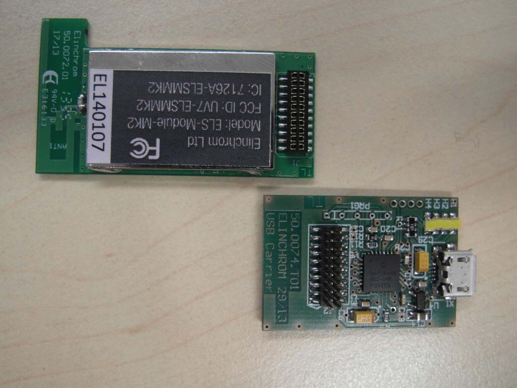
EL-Skyport MK 2 Module - FCC ID UV7-ELSMMK2 - Elinchrom SA
UV7-ELSMMK2

EL-Skyport MK 2 Module

Feb 18, 2014

Equipment Class

DTS - Digital Transmission System