UVLQCTSERIESQCT Series Transmitters
GAPOSA Srl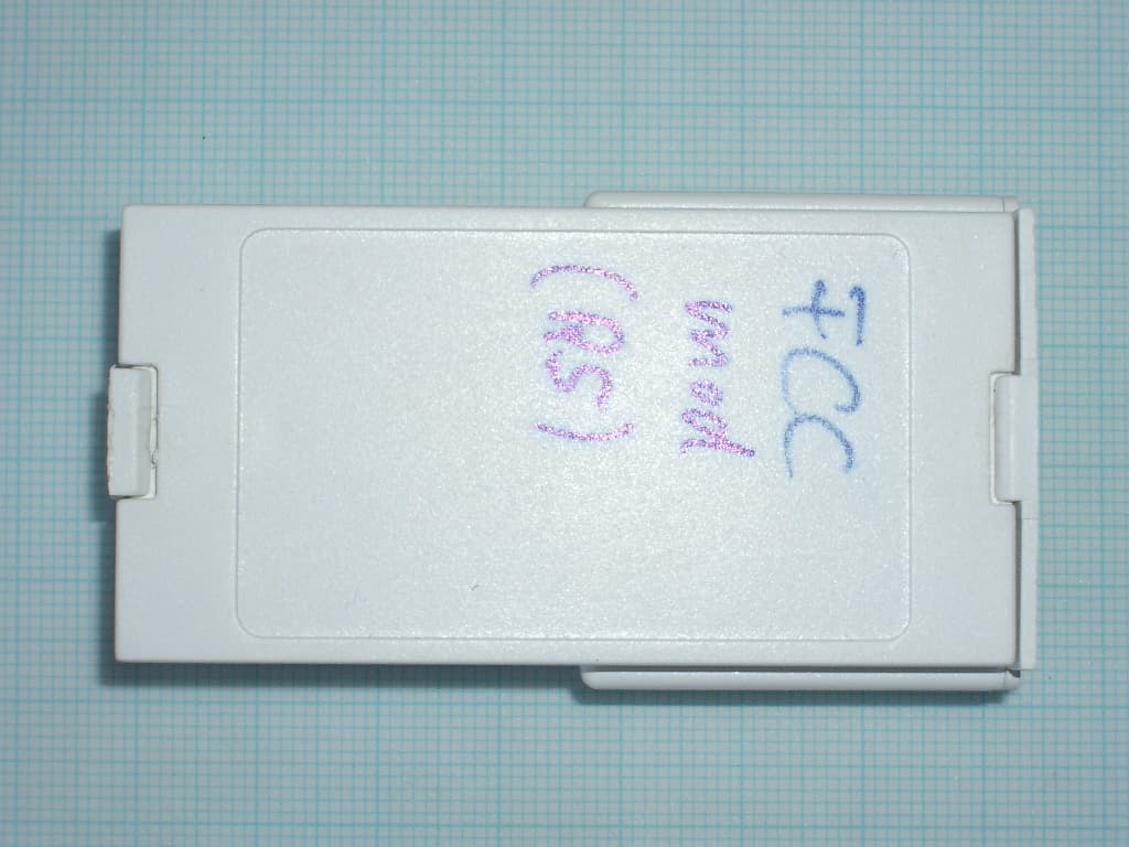
Click to zoom
Application Details
- Equipment Class
- DSC - Part 15 Security/Remote Control Transmitter
- Date of Grant
- Apr 02, 2008
- Application Purpose
- Original Equipment
- Date of Application
- Mar 30, 2008
- Equipment Note
- QCT Series Transmitters
- Frequency Range
- 434.15000000 - 434.15000000
- Company
- GAPOSA Srl
- Country
- Italy
Documents & Files
Document Text
Text extracted from the exhibit documents filed with the FCC. Open a document above to read the original.
Users Manual
Prog-Tx Led Prog-FC UP STOP DOWN Prog-Tx SEL Led Prog-FC UP STOP DOWN Installation guide QCT3-QCT3S-QCT3SD QCT34-QCT34S (Just for the electronic limit switch motors AXEL-AXELO RI) ® TECHNICAL DATA ∑Dimensions: 70x70x19 mm ∑Protection rate: IP 30 ∑Radio frequency: 434.15 MHz ∑Range: 20 mt internal; 300 mt open air ∑1 buttonUP ∑1 buttonSTOP ∑1 buttonDOWN ∑1 Prog-Tx= Instruction button ∑1 Prog-FC= limit switch setup button (AXEL) ∑1 LED ∑2 Litium 3Vbatteries (CR2025 type) QCT34-QCT34S(additional features) ∑4 channel selection button ∑4 LEDs Both transmitters are compatible with: ∑QC19 ∑All the RI motors OPERATION of the 4 channels QCT34S The4channelstransmitterhasachannel selection button (SEL) with a sequence working mode:bypressingitrepeatlyyouchange channel. Selecting group of channels: Choose with the SEL button the first channel of the group, then push it again and keep it pushed until theLEDstartsblinking. Whenmoving through the channels you can confirmthe channel to be added by pushing the SEL button until the LED stops blinking. In order to confirmthe group selection push the STOPbutton. WiththeUP, STOP, DOWN buttons all the motors belonging to that group will be activated. Toeraseagroupandgoingbacktothethe sequenceworkingmodeyouhavetopush, release and then push again the SEL button. BATTERY SUBSTITUTIONS 1.Openthecoverbyleveringupthehookonthe transmitter’s bottom 2.Lift thetransmitter card, thenremovetheusedup batteries 3.Insert thenewbatteriesandcheckthepolarity: - towards the card/+ towards the cover bottom CONFORMITY DECLARATION GAPOSA srl declares that the QCT Series is in conformity withtheessenatialrequirementsandwiththeother disposition established by the 1999/5/EC law. ThesedevicescompliewithPart 15of theFCCRules. Operation is subject to the following two conditions: (1) this devicemay not causeharmful interference, and, (2) this devicemust accept anyinterferencereceived, including interference thet may cause undesired operation”. Changes or modifications not expressly approvedby the partyresponsiblefor compliancecouldvoidtheuser’s authority to operate the equipment. OPERATION AND WARNINGS TheQCT Series transmittersenable the user to control one or more motors with receiver, installed on awnings, curtains and screens. It is possible to setup themwith group commands, in order to let more motors work simultaneously. The radio signal is shown by the transmission LED. If the LED doesn’t blink after the button pressure, then the battery has to be replaced. CAUTION: Please don’t use these transmitters in areas with risks of radio disturbs over the norm (i.e. airports or radio repeaters). These transmitters may also be disturbed by telecommunication plants and trans-ceiver with the same frequency. PROGRAMMING 1.Power up the motor to be programmed 2.Hold theProg-Txbutton until the motor starts moving. 3.Checktherotationwayof themotor, then release theProg-Txbutton. 4.Within5secondspressthe correspondingbutton(i.e.UPifthe motor rotatestothetopor DOWNif viceversa). Inthiswaythetransmitterhasbeen programmed as MASTERand therotation direction of the motor has been syncronized. IMPORTANT: Whilst you keep pressing the Prog-Txbuttonthemotorwill keepon turninginonedirection. By releasingand pressing it again the motor will rotate in the other direction (sequence working). LIMIT SWITCH SETUP UP LIMIT SWITCH 1.Pushthe Prog-Fcbutton till it makes a small movement in both direction, then press the UP button 2.Be ready to press the STOP button when themotorreachesthedesiredlimit switch position or wait till the motor stops automatically on the limit positions of the curtain/awning. Inbothcases thelimit switchsetupsthepositionwherethe motor stops. 3.For an accurate setup press theProg-Fc button while the motor is running. The motorwillmoveslowlyandjerkily towards the limit switch position. DOWN LIMIT SWITCH 4.PushtheDownbuttonandbe readytostopthemotor(by pressing the STOPbutton) when thedesiredlimit switchposition has been reached. 5.For anaccurate setuppress the Prog-Fc button while the motor is running.Themotorwillmove slowlyandjerkilytowardsthe DOW N limit switch position. ADDING MORE TRANSMITTERS/CHANNELS 1.Keep pushing the MASTERProg-Txbutton till the motor starts running 2.Checkthemotorrotationdirection,then release theProg-Txbutton. 3.Within5secondspressthecorrisponding button (i.e. UP if the motor rotates to the top or DOWNif viceversa) of thenewQCT3Sor QCT34S you wish to add. In this way a newtransmitter has been added to the motor receiver. TRANSMITTERS ERASE 1.Push simultanously theProg-TxandSTOP buttons of the MASTER transmitter until the motor makesasmall movement inboth directions. CANCELLING WITHOUT MASTER 1.Remove power. 2.Push simultaneously theProg TxandSTOP buttons of a newQCT3SorQCT34Sand then power up the motor again until it makes a small movement in both directions. INTERMEDIATE POSITION SETUP 1.Bringthecurtain/awninginthedesired intermediateposition,thenpress simultaneouslytheUPandDOWNbuttons until the motor makes a small movement in both directions. The intermediate position has been setup. RECALLING THE INTERMEDIATE POSITION Keep pushing the STOPbutton for 3 seconds at least: the curtain/awning will move till it reaches the intermediate position. ERASING THE INTERMEDIATE POSITION. Push simultaneously the UPand DOWNbuttons until the motor makes a small movement in both directions. CAUTION:If more motors with receiver have to be installed, then just one motor has to be powered up during the first programming session, in order to avoid nterferences with the other motors. CAUTION: The first limit switch to setup is always the UP one.
Block Diagram
Evaluation of GAPOSA FCC ID: UVLQCTSERIES 1.DESCRIPTION 2.ANALYSIS OF DERIVED PRODUCT 3.INSTALLATION RULES AND POSSIBLE USE LIMITATIONS 4.CONFORMITY TO EUROPEAN STANDARDS 1.DESCRIPTION Typical uses of these devices are remote controls rolling shutters or rolling curtains. The working frequencyof this remote controls is 434.15 Mhz (± 75Khz), they are saw based Colpittsoscillator, OOK carrier modulated. A frame of 64 bits contains all the needed information to be recognized by the receiver. The frame architecture is show below. They are power supplied by two lithium batteries in series (size CR2025). FRAME ARCHITECHTURE A 64bitserial string forms the frame. Start bit(1bit)Frame(6 4 bits)Pause 2.6 ms82.8 ms15.5 ms Four Channels version UP command key(i.e. for opening the rolling shutter) STOP command key(i.e. for stopping the rolling shutter) DOWN command key(i.e. for closing the rolling shutter) SELC programming key PROGFC programming key PROGTX programming key LEDchannel identifier (1up to 4 or grouping) LEDS UP STOP DOWN SELC PROGFC PROGTX DINAMIC CODE SYSTEM ID SERIAL CODE CHANNELS COMAND ROLLING CODE One channel version LED UP STOP DOWN PROGFC PROGTX 2. ANALYSIS OF DERIVED PRODUCT All versions use the same p.c.b (printed circuit board), the main difference is the number of LEDs and programming keys mounted on the PCB. Transmitters K 13802 are the same as K 13801 with the exception of the saw resonator size (3.5 x 5 mm for K13801 and 3 x 3 mm for K13802). 3. INSTALLATION RULES AND POSSIBLE USE LIMITATIONS Duty cycle has to be < of 0.1% 4. CONFORMITY TO EUROPEAN STANDARDS The equipment complies with European StandardEN 300 220-1 (2006)
Cover Letter(s)
Fermo, 28/03/2007Federal Communications Commission 7435 OaklandMills Road Columbia, MD 21046 Gentlemen, This letter is to comply with Sections 0.457 and 0.459 pertaining to confidential material. GAPOSA SRL would like to following documents regarding this submissionfor FCC FCC ID: UVL to be kept confidential. 1.Document:Schematics, type K13801 LC The above material contains trade secrets or technical data, which would customarily be guarded from competitors. We donot want these documents to be accessible to the general public. Sincerely, GAPOSA SRL Quality Manager Eng. Fadi MAHFOUZ Fadi MAHFOUZ ViaEte, 90 I-63023 FERMO (AP) Tel.:+39/0734/22.07.1 Fax:+39/0734/22.63.89 Mobile:+39/340/67.90.55.1
External Photos
RADIO LABORATORIES EMC LABORATORIES DAT-P-204/95 EMCC DR. RAŠEK Moggast, Boelwiese 8 91320 Ebermannstadt Germany FCC Registration # 90566 Annex2_ACAA1.doc Telephone: +49-9194-9016 Telefax: +49-9194-8125 Mail: [email protected] Web: http://www.emcc.de PAGE 1 of 6 ANNEX 2 TO TEST REPORT # EMCC-051027ACAA, 2006-08-07 PHOTOGRAPHS OF TEST SAMPLE EQUIPMENT UNDER TEST: Name: Remote Control Systems Model: QCT3 Serial No: none Equipment Category: Transmitter Manufacturer: GAPOSA srl Address: Contrada Ete, 90 63023 Fermo (AP) Italy Phone: ++39-07342207138 Fax: ++39-0734226389 RELEVANT STANDARD: 47 CFR Part 15C - Intentional Radiators CONTENTS Page 1 External view ........................................................................................................................................................ 2 1.1 Photograph: Front view .............................................................................................................................. 2 1.2 Photograph: Rear view............................................................................................................................... 3 2 Internal view ......................................................................................................................................................... 4 2.1 Photograph: Housing opened, Side 1 of PCB............................................................................................ 4 2.2 Photograph: Side 1 of PCB ........................................................................................................................ 5 2.3 Photograph: Side 2 of PCB ........................................................................................................................ 6 Annex 2 to Test Report #EMCC-051027ACAA Page 2 of 6 Issue Date: 2006-08-07 TEST OF GAPOSA SRL MODEL QCT3 TO 47 CFR PART 15C - INTENTIONAL RADIATORS ANNEX2_ACAA1.DOC 1 EXTERNAL VIEW 1.1 Photograph: Front view Remark: grid = 1 mm Annex 2 to Test Report #EMCC-051027ACAA Page 3 of 6 Issue Date: 2006-08-07 TEST OF GAPOSA SRL MODEL QCT3 TO 47 CFR PART 15C - INTENTIONAL RADIATORS ANNEX2_ACAA1.DOC 1.2 Photograph: Rear view Annex 2 to Test Report #EMCC-051027ACAA Page 4 of 6 Issue Date: 2006-08-07 TEST OF GAPOSA SRL MODEL QCT3 TO 47 CFR PART 15C - INTENTIONAL RADIATORS ANNEX2_ACAA1.DOC 2 INTERNAL VIEW 2.1 Photograph: Housing opened, Side 1 of PCB Annex 2 to Test Report #EMCC-051027ACAA Page 5 of 6 Issue Date: 2006-08-07 TEST OF GAPOSA SRL MODEL QCT3 TO 47 CFR PART 15C - INTENTIONAL RADIATORS ANNEX2_ACAA1.DOC 2.2 Photograph: Side 1 of PCB Annex 2 to Test Report #EMCC-051027ACAA Page 6 of 6 Issue Date: 2006-08-07 TEST OF GAPOSA SRL MODEL QCT3 TO 47 CFR PART 15C - INTENTIONAL RADIATORS ANNEX2_ACAA1.DOC 2.3 Photograph: Side 2 of PCB
Internal Photos
RADIO LABORATORIES EMC LABORATORIES DAT-P-204/95 EMCC DR. RAŠEK Moggast, Boelwiese 8 91320 Ebermannstadt Germany FCC Registration # 90566 Annex2_ACAA1.doc Telephone: +49-9194-9016 Telefax: +49-9194-8125 Mail: [email protected] Web: http://www.emcc.de PAGE 1 of 6 ANNEX 2 TO TEST REPORT # EMCC-051027ACAA, 2006-08-07 PHOTOGRAPHS OF TEST SAMPLE EQUIPMENT UNDER TEST: Name: Remote Control Systems Model: QCT3 Serial No: none Equipment Category: Transmitter Manufacturer: GAPOSA srl Address: Contrada Ete, 90 63023 Fermo (AP) Italy Phone: ++39-07342207138 Fax: ++39-0734226389 RELEVANT STANDARD: 47 CFR Part 15C - Intentional Radiators CONTENTS Page 1 External view ........................................................................................................................................................ 2 1.1 Photograph: Front view .............................................................................................................................. 2 1.2 Photograph: Rear view............................................................................................................................... 3 2 Internal view ......................................................................................................................................................... 4 2.1 Photograph: Housing opened, Side 1 of PCB............................................................................................ 4 2.2 Photograph: Side 1 of PCB ........................................................................................................................ 5 2.3 Photograph: Side 2 of PCB ........................................................................................................................ 6 Annex 2 to Test Report #EMCC-051027ACAA Page 2 of 6 Issue Date: 2006-08-07 TEST OF GAPOSA SRL MODEL QCT3 TO 47 CFR PART 15C - INTENTIONAL RADIATORS ANNEX2_ACAA1.DOC 1 EXTERNAL VIEW 1.1 Photograph: Front view Remark: grid = 1 mm Annex 2 to Test Report #EMCC-051027ACAA Page 3 of 6 Issue Date: 2006-08-07 TEST OF GAPOSA SRL MODEL QCT3 TO 47 CFR PART 15C - INTENTIONAL RADIATORS ANNEX2_ACAA1.DOC 1.2 Photograph: Rear view Annex 2 to Test Report #EMCC-051027ACAA Page 4 of 6 Issue Date: 2006-08-07 TEST OF GAPOSA SRL MODEL QCT3 TO 47 CFR PART 15C - INTENTIONAL RADIATORS ANNEX2_ACAA1.DOC 2 INTERNAL VIEW 2.1 Photograph: Housing opened, Side 1 of PCB Annex 2 to Test Report #EMCC-051027ACAA Page 5 of 6 Issue Date: 2006-08-07 TEST OF GAPOSA SRL MODEL QCT3 TO 47 CFR PART 15C - INTENTIONAL RADIATORS ANNEX2_ACAA1.DOC 2.2 Photograph: Side 1 of PCB Annex 2 to Test Report #EMCC-051027ACAA Page 6 of 6 Issue Date: 2006-08-07 TEST OF GAPOSA SRL MODEL QCT3 TO 47 CFR PART 15C - INTENTIONAL RADIATORS ANNEX2_ACAA1.DOC 2.3 Photograph: Side 2 of PCB
Operational Description
Evaluation of GAPOSA FCC ID: UVLQCTSERIES 1.DESCRIPTION 2.ANALYSIS OF DERIVED PRODUCT 3.INSTALLATION RULES AND POSSIBLE USE LIMITATIONS 4.CONFORMITY TO EUROPEAN STANDARDS 1.DESCRIPTION Typical uses of these devices are remote controls rolling shutters or rolling curtains. The working frequencyof this remote controls is 434.15 Mhz (± 75Khz), they are saw based Colpittsoscillator, OOK carrier modulated. A frame of 64 bits contains all the needed information to be recognized by the receiver. The frame architecture is show below. They are power supplied by two lithium batteries in series (size CR2025). FRAME ARCHITECHTURE A 64bitserial string forms the frame. Start bit(1bit)Frame(6 4 bits)Pause 2.6 ms82.8 ms15.5 ms Four Channels version UP command key(i.e. for opening the rolling shutter) STOP command key(i.e. for stopping the rolling shutter) DOWN command key(i.e. for closing the rolling shutter) SELC programming key PROGFC programming key PROGTX programming key LEDchannel identifier (1up to 4 or grouping) LEDS UP STOP DOWN SELC PROGFC PROGTX DINAMIC CODE SYSTEM ID SERIAL CODE CHANNELS COMAND ROLLING CODE One channel version LED UP STOP DOWN PROGFC PROGTX 2. ANALYSIS OF DERIVED PRODUCT All versions use the same p.c.b (printed circuit board), the main difference is the number of LEDs and programming keys mounted on the PCB. Transmitters K 13802 are the same as K 13801 with the exception of the saw resonator size (3.5 x 5 mm for K13801 and 3 x 3 mm for K13802). 3. INSTALLATION RULES AND POSSIBLE USE LIMITATIONS Duty cycle has to be < of 0.1% 4. CONFORMITY TO EUROPEAN STANDARDS The equipment complies with European StandardEN 300 220-1 (2006)
Test Setup Photos
RADIO LABORATORIES EMC LABORATORIES DAT-P-204/95 EMCC DR. RAŠEK Moggast, Boelwiese 8 91320 Ebermannstadt Germany FCC Registration # 90566 Annex1_ACAA.doc Telephone: +49-9194-9016 Telefax: +49-9194-8125 Mail: [email protected] Web: http://www.emcc.de Page 1 of 5 ANNEX 1 TO TEST REPORT # EMCC-051027ACAA, 2006-08-07 PHOTOGRAPHS OF TEST SETUPS EQUIPMENT UNDER TEST: Name: Remote Control Systems Model: QCT3 Serial No: none Equipment Category: Transmitter Manufacturer: GAPOSA srl Address: Contrada Ete, 90 63023 Fermo (AP) Italy Phone: ++39-07342207138 Fax: ++39-0734226389 RELEVANT STANDARD: 47 CFR Part 15C - Intentional Radiators CONTENTS Page 1 CONDUCTED EMISSIONS TEST ......................................................................................................................... 2 1.1 Photograph: none....................................................................................................................................... 2 2 RADIATED EMISSIONS TEST ............................................................................................................................. 3 2.1 Photograph: Electric field, prescan, f = 30 MHz to 1 GHz, EUT vertical.................................................... 3 2.2 Photograph: Electric field, f = 30 MHz to 1 GHz, EUT horizontal .............................................................. 4 2.3 Photograph: Electric field, f > 1 GHz, EUT horizontal ................................................................................ 5 Annex 1 to Test Report #EMCC-051027ACAA Page 2 of 5 Issue Date: 2006-08-07 TEST OF GAPOSA SRL MODEL QCT3 TO 47 CFR PART 15C - INTENTIONAL RADIATORS ANNEX1_ACAA.DOC 1 CONDUCTED EMISSIONS TEST 1.1 Photograph: none not applicable Annex 1 to Test Report #EMCC-051027ACAA Page 3 of 5 Issue Date: 2006-08-07 TEST OF GAPOSA SRL MODEL QCT3 TO 47 CFR PART 15C - INTENTIONAL RADIATORS ANNEX1_ACAA.DOC 2 RADIATED EMISSIONS TEST 2.1 Photograph: Electric field, prescan, f = 30 MHz to 1 GHz, EUT vertical Annex 1 to Test Report #EMCC-051027ACAA Page 4 of 5 Issue Date: 2006-08-07 TEST OF GAPOSA SRL MODEL QCT3 TO 47 CFR PART 15C - INTENTIONAL RADIATORS ANNEX1_ACAA.DOC 2.2 Photograph: Electric field, f = 30 MHz to 1 GHz, EUT horizontal Annex 1 to Test Report #EMCC-051027ACAA Page 5 of 5 Issue Date: 2006-08-07 TEST OF GAPOSA SRL MODEL QCT3 TO 47 CFR PART 15C - INTENTIONAL RADIATORS ANNEX1_ACAA.DOC 2.3 Photograph: Electric field, f > 1 GHz, EUT horizontal
Contact Information
Applicant
Fadi Mahfouz
Test Firm
EMCCons Dr. Rasek GmbH & Co. KGWinfried hoffmann
Technical Specifications
| # | Rule Parts | Frequency Range | Power Output |
|---|---|---|---|
| 1 | 15.231 | 434.15 MHz - 434.15 MHz | - |