UVQ-YJ-SWAP30G802.11g Super Wireless Access Point
yVes Technology CO., LTD.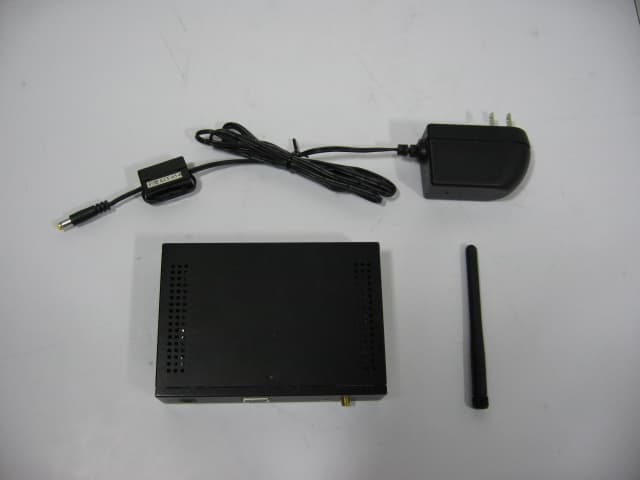
Click to zoom
Application Details
- Equipment Class
- DTS - Digital Transmission System
- Date of Grant
- Feb 28, 2007
- Application Purpose
- Original Equipment
- Date of Application
- Feb 28, 2007
- Equipment Note
- 802.11g Super Wireless Access Point
- Frequency Range
- 2412.00000000 - 2462.00000000
- Company
- yVes Technology CO., LTD.
- Country
- Taiwan
Documents & Files
Document Text
Text extracted from the exhibit documents filed with the FCC. Open a document above to read the original.
Users Manual
Regulatory Approvals FCC Statement This equipment has been tested and found to comply with the limits for a Class B digital device, pursuant to Part 15 of the FCC Rules. These limits are designed to provide reasonable protection against harmful interference in a residential installation. This equipment generates, uses and can radiate radio frequency energy and, if not installed and used in accordance with the instructions, may cause harmful interference to radio communica- tions. However, there is no guarantee that interference will not occur in a particular installation. If this equipment does cause harmful interference to radio or television reception, which can be determined by turning the equipment off and on, the user is encouraged to try to correct the interference by one of the following measures: Reorient or relocate the receiving antenna. Increase the separation between the equipment and receiver. Connect the equipment into an outlet on a circuit different from that to which the receiver is connected. Consult the dealer or an experienced radio/TV technician for help. To assure continued compliance, any changes or modifications not expressly approved by the party responsible for compliance could void the user's authority to operate this equipment. (Example - use only shielded interface cables when connecting to computer or peripheral devices). FCC Radiation Exposure Statement This equipment complies with FCC RF radiation exposure limits set forth for an uncontrolled environment. This equipment should be installed and operated with a minimum distance of 20 centimeters between the radiator and your body. This device complies with Part 15 of the FCC Rules. Operation is subject to the following two conditions: (1) This device may not cause harmful interference, and (2) This device must accept any interference received, including interference that may cause undesired operation. This transmitter must not be co-located or operating in conjunction with any other antenna or transmitter. The antennas used for this transmitter must be installed to provide a separation distance of at least 20 cm from all persons and must not be co-located or operating in conjunction with any other antenna or transmitter. Channel The Wireless Channel sets the radio frequency used for communication. Access Points use a fixed Channel. You can select the Channel used. This allows you to choose a Channel which provides the least interference and best performance. In the USA and Canada, 11 channel are available. If using multiple Access Points, it is better if adjacent Access Points use different Channels to reduce interference. In "Infrastructure" mode, Wireless Stations normally scan all Channels, looking for an Access Point. If more than one Access Point can be used, the one with the strongest signal is used. (This can only happen within an ESS.) If using "Ad-hoc" mode (no Access Point), all Wireless stations should be set to use the same Channel. However, most Wireless stations will still scan all Channels to see if there is an existing "Ad-hoc" group they can join. Note: This equipment marketed in USA is restricted by firmware to only operate on 2.4G channel 1-11 SAP30g Super Access Point Instllation Guide Version 1.1.0 (4/28/2006) Content 1 Installation..............................................................................................................3 1.1 Package list ............................................................................................3 1.2 Hardware Installation.............................................................................3 2 How to Start ...........................................................................................................3 2.1 Before start to configure ........................................................................3 2.2 What the SAP30g acts ...........................................................................3 2.2.1 Access Point...................................................................................3 2.2.2 Client..............................................................................................3 2.2.3 WDS...............................................................................................3 2.2.4 WDS + AP .....................................................................................3 2.2.5 AP + Repeater ................................................................................3 3 Configuration .........................................................................................................4 3.1 Configure AP by Wizard ........................................................................4 3.1.1 Open configuration page http://192.168.1.250..........................4 3.1.2 After password check, wizard will be executed.............................4 3.1.3 LAN Interface Setup ......................................................................5 3.1.4 Wireless Basic Setting ...................................................................5 3.1.4.1 AP setting ................................................................................6 3.1.4.2 Client Setting ..........................................................................6 3.1.4.3 WDS Setting ...........................................................................7 3.1.4.4 WDS+AP Setting ....................................................................7 3.1.5 Wireless Security Setup .................................................................8 3.1.5.1 Security (WEP) .......................................................................8 3.1.5.2 Security WPA(TKIP) ..............................................................9 3.1.5.3 Security WPA2 (AES).............................................................9 3.1.5.4 Security WPA2 (Mixed)........................................................10 3.1.6 Finish......................................................................................…
Text truncated - open the document above for the full version.
External Photos
Project No.: 0610003 Page 2 of 1 0 Neutron Engineering Inc. 0610003 Project No.: 0610003 Page 3 of 1 0 Neutron Engineering Inc. 0610003 0610003
ID Label/Location Info
Model No: SAP30g FCC ID: UVQ-YJ-SWAP30G Made in Taiwan This device complies with Part 15 of the FCC Rules. Operation is subject to the following two conditions: (1) This device may not cause harmful interference, and (2) this device must accept any interference received, including interference that may cause undesired operation.
Internal Photos
Project No.: 0610003 Page 4 of 1 0 Neutron Engineering Inc. 0610003 0610003 Project No.: 0610003 Page 5 of 1 0 Neutron Engineering Inc. 0610003 0610003 Project No.: 0610003 Page 6 of 1 0 Neutron Engineering Inc. 0610003 0610003 Project No.: 0610003 Page 7 of 1 0 Neutron Engineering Inc. 0610003 0610003 Project No.: 0610003 Page 8 of 1 0 Neutron Engineering Inc. 0610003 Project No.: 0610003 Page 9 of 1 0 Neutron Engineering Inc. 0610003 0610003 Project No.: 0610003 Page 10 of 10 Neutron Engineering Inc. 0610003 0610003
Operational Description
1. CPU, U16, RTL8186 is a highly integrated System-on-a-Chip with a high-performance 32-bit RISC micro-controller, two Ethernet MACs, and a WLAN controller embedded onto a single chip. The embedded 32-bit RISC CPU runs at up to 180MHz and features separate 8K instruction and data caches. It needs an external 40MHz oscillator for reference frequency; this oscillator is also used for RF module. This chip is responsible to control RF-Baseband Transceiver (RTL8225). The RTL8186 features two fast Ethernet MACs; one perhaps used for a LAN interface and the other connected to a WAN port. An IEEE 802.11a/b/g WLAN MAC and base-band processor is embedded. The RTL8186 provides a glueless interface for external SDRAM and flash memory devices. It allows customers to use 1MB to 64MB SDRAM/flash memory with 16-bit or 32-bit variable length in great flexibility. The RTL8186/RTL8186P also supports NOR and NAND type flash, and system booting from the NAND type flash is at no extra cost. Additionally, The RTL8186 provides UART, PCI, and PCM interfaces as well as up to 58 GPIO (General Purpose I/O) pins. With the PCM interface, wireless VoIP applications are made possible. 2. FLASH, U17, MX29LV160CBTC-70G, 16Mbits Flash, bottom boot sector, 70ns. It is used to store the normal and test firmware. SDRAM, U18, M12L64164A-7TG is 67,108,864 bits synchronous Dynamic RAM organized as 4 x 1,048,576 words by 16bits. It is used to store the dynamic operation code. 3. The RTL8225 is a fully integrated RF transceiver compliant with IEEE Wireless LAN standards 802.11b, and 802.11g. When used with a baseband/MAC processor (e.g. RTL8186) and a 2.4GHz power amplifier, it forms a complete solution for the 2.4GHz ISM band. The RTL8225 uses direct conversion/zero-IF architecture to limit the number of required active blocks and avoid external, cumbersome, IF band-pass SAW filters for channel selection. The receive path includes sets of single-ended Low Noise Amplifiers (LNA), followed by RF-to-baseband I/Q demodulators, baseband filters, and discrete-step variable-gain amplifiers. The entire receive chain provides linear and monotonic automatic gain control, RSSI signal, and fast DC offset cancellation mechanisms to a baseband processor. The transmitter path includes integrated reconstruction filters, discrete-step variable-gain amplifiers, a baseband-to-RF I/Q modulator, and pre amplifiers. A linear and monotonic gain control is distributed throughout the transmitter chain to ensure high linearity as well as to simplify Automatic Gain Control (AGC). The modulator and demodulator are driven by an internal Voltage Controlled Oscillator (VCO). The VCO is phase-locked by an internal 3-wire-interfaced PLL. The RTL8225 needs two external LDO regulators, one is DC3V0 (U6), and other is 1V8 (U7). It is also need external oscillator to generate a 40MHz (X1) clock source as input to the RTL8225. 4. Driver amplifier, U10, SE2527L is a 2.4 GHz power amplifier designed for use in the 2.4 GHz ISM band for wireless LAN applications. The device incorporates a power detector for closed loop monitoring of the output power. Power amplifier, U1, RF2163 is a linear, medium power, high efficiency amplifier IC has been designed for use as the final RF amplifier in 2.4GHz spread-spectrum transmitters. The device is provided in a 16-pin leadless chip carrier with a backside ground and is self-contained with the exception of the output matching network and power supply feed line. 5. Power part: there are several regulators are used on this system. U_5Vrf1, U_P1, MP1583DN is used to transfer DC18V to DC5V and DC3V3; U6, CM2838GPIM25 is used to transfer DC3V3 to DC3V; U7 CM2838GDIM25 is used to transfer DC3V3 to DC1V8, U2, 1117-ADJ is used to transfer DC3V3 to DC1V8. 6. U20, RTL8201CP is a single-chip/single-port PHYceiver with a MII (Media Independent Interface)/SNI (Serial Network Interface). It implements all 10/100M Ethernet Physical-layer functions including the Physical Coding Sublayer (PCS), Physical Medium Attachment (PMA), Twisted Pair Physical Medium Dependent Sublayer (TP-PMD), with an auto crossover detection function, 10Base-Tx Encoder/Decoder, and Twisted-Pair Medium Access Unit (TPMAU). 8. GaAs IC SPDT Switch, U5, AS193-73, features use where extremely high linearity, low control voltage, high isolation, low insertion loss and ultra miniature package size are required, and very low DC power consumption. It used to implementations a RF Transmit and Receive switch.
RF Exposure Info
1.1. Test Result of RF Exposure Evaluation . Product: 802.11g Super Wireless Access Point . Test Item: RF Exposure Evaluation Data . Test site: OATSI-SD . Test Mode: Normal Operation 1.1.1. Antenna Gain The maximum Gain is 2.0 dBi. 1.1.2. EUT Operation condition Software provided by client enabled the EUT to transmit and receive data at lowest, middle and highest channel individually. 1.1.3. Output Power into Antenna & RF Exposure Evaluation Distance Modulation Standard: 802.11b Test Date: Oct. 2, 2006 Temperature: 27 °C Humidity: 55% Channel Channel Frequency (MHz) Output Power to Antenna (dBm) Power Density (S) (mW/cm 2 ) 01 2412 23.13 0.064856 06 2437 23.14 0.065006 11 2462 23.13 0.064856 Modulation Standard: 802.11g Test Date: Oct. 2, 2006 Temperature: 27 °C Humidity: 55% Channel Channel Frequency (MHz) Output Power to Antenna (dBm) Power Density (S) (mW/cm 2 ) 01 2412 23.20 0.067445 06 2437 23.17 0.065456 11 2462 23.17 0.065456 The MPE is calculated as 0.067445 mW / cm 2 < limit 1 mW / cm 2 . So, RF exposure limit warning or SAR test are not required. For 2400-2483.5 MHz, the EUT will only be used with a separation of 20cm or greater between the antenna and nearby persons and can therefore be considered a mobile transmitter per 47CFR2.1091 (b). The RF Exposure Information page from the manual is included here for reference.
Test Report
Report No.: NEI-FCCP-1-0609066 Page 2 of 86 Neutron Engineering Inc. Declaration Neutron represents to the client that testing is done in accordance with standard procedures as applicable and that test instruments used has been calibrated with the standards traceable to National Measurement Laboratory (NML) of R.O.C., or National Institute of Standards and Technology (NIST) of U.S.A. Neutron's reports apply only to the specific samples tested under conditions. It is manufacture’s responsibility to ensure that additional production units of this model are manufactured with the identical electrical and mechanical components. Neutronshall have no liability for any declarations, inferences o r generalizations drawn by the client or others from Neutron issued reports. Neutron’s reports must not be used by the client to claim product endorsement by the authorities or any agency of the Government. This report is the confidential property of the client. As a mutual protection to the clients, the public and Neutron-self, extracts from the test report shall not be reproduced except in full with Neutron’s authorized written approval. Neutron’s laboratory quality assurance procedures are in compliance with the ISO Guide 17025 requirements, and accredited by the conformity assessment authorities listed in this test report. Limitation For the use of the authority's logo is limited unless the Test Standard(s)/Scope(s)/Item(s) mentioned in this test report is (are) included in the conformity assessment authorities acceptance respective. Report No.: NEI-FCCP-1-0609066 Page 3 of 86 Neutron Engineering Inc. Table of Contents Page 1 . CERTIFICATION 5 2 . SUMMARY OF TEST RESULTS 6 2.1 TEST FACILITY 7 2.2 MEASUREMENT UNCERTAINTY 7 3 . GENERAL INFORMATION 8 3.1 GENERAL DESCRIPTION OF EUT 8 3.2 DESCRIPTION OF TEST MODES 9 3.3 BLOCK DIGRAM SHOWING THE CONFIGURATION OF SYSTEM TESTED 10 3.4 DESCRIPTION OF SUPPORT UNITS 11 4 . EMC EMISSION TEST 12 4.1 CONDUCTED EMISSION MEASUREMENT 12 4.1.1 POWER LINE CONDUCTED EMISSION LIMITS 12 4.1.2 MEASUREMENT INSTRUMENTS LIST 12 4.1.3 TEST PROCEDURE 13 4.1.4 DEVIATION FROM TEST STANDARD 13 4.1.5 TEST SETUP 13 4.1.6 EUT OPERATING CONDITIONS 14 4.1.7 TEST RESULTS 15 4.2 RADIATED EMISSION MEASUREMENT 19 4.2.1 RADIATED EMISSION LIMITS 19 4.2.2 MEASUREMENT INSTRUMENTS LIST 20 4.2.3 TEST PROCEDURE 20 4.2.4 DEVIATION FROM TEST STANDARD 20 4.2.5 TEST SETUP 21 4.2.6 EUT OPERATING CONDITIONS 21 4.2.7 TEST RESULTS (Between 30 – 1000 MHz) 22 4.2.8 TEST RESULTS (Above 1000 MHz) 34 4.2.9 TEST RESULTS (Restricted Bands Requirements) 58 5 . BANDWITH TEST 66 5.1 APPLIED PROCEDURES / LIMIT 66 5.1.1 MEASUREMENT INSTRUMENTS LIST 66 5.1.2 TEST PROCEDURE 66 5.1.3 DEVIATION FROM STANDARD 66 5.1.4 TEST SETUP 66 5.1.5 EUT OPERATION CONDITIONS 66 5.1.6 TEST RESULTS 67 Report No.: NEI-FCCP-1-0609066 Page 4 of 86 Neutron Engineering Inc. Table of Contents Page 6 . PEAK OUTPUT POWER TEST 71 6.1 APPLIED PROCEDURES / LIMIT 71 6.1.1 MEASUREMENT INSTRUMENTS LIST 71 6.1.2 TEST PROCEDURE 71 6.1.3 DEVIATION FROM STANDARD 71 6.1.4 TEST SETUP 71 6.1.5 EUT OPERATION CONDITIONS 71 6.1.6 TEST RESULTS 72 7 . ANTENNA CONDUCTED SPURIOUS EMISSION 73 7.1 APPLIED PROCEDURES / LIMIT 73 7.1.1 MEASUREMENT INSTRUMENTS LIST 73 7.1.2 TEST PROCEDURE 73 7.1.3 DEVIATION FROM STANDARD 73 7.1.4 TEST SETUP 73 7.1.5 EUT OPERATION CONDITIONS 73 7.1.6 TEST RESULTS 74 8 . POWER SPECTRAL DENSITY TEST 78 8.1 APPLIED PROCEDURES / LIMIT 78 8.1.1 MEASUREMENT INSTRUMENTS LIST 78 8.1.2 TEST PROCEDURE 78 8.1.3 DEVIATION FROM STANDARD 78 8.1.4 TEST SETUP 78 8.1.5 EUT OPERATION CONDITIONS 78 8.1.6 TEST RESULTS 79 9 . RF EXPOSURE TEST 83 9.1 APPLIED PROCEDURES / LIMIT 83 9.1.1 MEASUREMENT INSTRUMENTS LIST 83 9.1.2 TEST RESULTS 84 10 . EUT TEST PHOTO 85 Report No.: NEI-FCCP-1-0609066 Page 5 of 86 Neutron Engineering Inc. 1. CERTIFICATION E q u i p m e n t : 802.11g Super Wireless Access Point M o d e l N o . : SPA30G A p p l i c a n t : yVes Technology Co., LTD. Data of Test : Oct. 02, 2006 ~ Nov. 06, 2006 Te s t I t e m : ENGINEERING SAMPLE Standards : FCC Part15, Subpart C / RSS-210: 2004/ ANCI C63.4 : 2003 The above equipment has been tested and found compliance with the requirement of the relative standards by Neutron Engineering Inc. EMC Laboratory. The test data, data evaluation, and equipment configuration contained in our test report (Ref No. NEI-FCCP-1-0610003) were obtained utilizing the test procedures, test instruments, test sites that has been accredited by the Authority of NVLAP and CNLA according to the ISO-17025 quality assessment standard and technical standard(s). Report No.: NEI-FCCP-1-0609066 Page 6 of 86 Neutron Engineering Inc. 2. SUMMARY OF TEST RESULTS Test procedures according to the technical standards: FCC Part15, Subpart C Standard Section Test Item Judgment Remark 15.207 Conducted Emission PASS 15.247 (c) Antenna conducted Spurious Emission PASS 15.247 (a)(2) 6dB Bandwidth PASS 15.247 (b) Peak Output Power PASS 15.247 (c) Radiated Spurious Emission PASS 15.247 (d) Power Spectral Density PASS 15.203 Antenna Requirement PASS 1.1307 1.1310 2.1091 2.1093 RF Exposure Compliance PASS NOTE: (1)” N/A” denotes test is not applicable in this Test Report Report No.: NEI-FCCP-1-0609066 Page 7 of 86 Neutron Engineering Inc. 2.1 TEST FACILITY The test facilities used to collect the test data in this report is C01/OS02 at the location of No.132-1, Lane 329, Sec. 2, Palain Road, Shijr City, Taipei, Taiwan. 2.2 MEASUREMENT UNCERTAINTY The reported uncertainty of measurement y ± U,where expended uncertainty U is based on a standard uncertainty multiplied by a coverage factor of k=2,providing a level of confidence of approximately 95 %。 A. Conducted Measurement : Test Site Method Measurement Frequency Range U,(dB) NOTE C01 ANSI150 KHz ~ 30MHz 1.94 B. Radiated Measurement : Test Site Method Measurement Frequency Range Ant. H / V U,(dB) NOTE OS-01 ANSI30MHz ~ 200MHz V 3.82 30MHz ~ 200MHz H 3.60 200MHz ~ 1,000MHz V 3.86 200MHz ~ 1,000MHz H 3.9…
Text truncated - open the document above for the full version.
Test Report
Report No.: NEI-FCCP-1-0609066 Page 66 of 8 6 Neutron Engineering Inc. 5. BANDWITH TEST 5.1 APPLIED PROCEDURES / LIMIT FCC Part15 (15.247) , Subpart C Section Test Item Limit Frequency Range (MHz) Result 15.247 (a)(2) Bandwidth >= 500KHz (6dB bandwidth) 2400-2483.5 PASS 5.1.1 MEASUREMENT INSTRUMENTS LIST Item Kind of Equipment Manufacturer Type No. Serial No. Calibrated until 1 Spectrum Analyzer R&S FSP_40 100129 Jan. 09, 2007 Remark: ” N/A” denotes No Model No. , Serial No. or No Calibration specified. 5.1.2 TEST PROCEDURE a. The EUT was directly connected to the spectrum analyzer and antenna output port as show in the block diagram below, b. Spectrum Setting : RBW= 100KHz, VBW=100KHz, Sweep time = Auto. 5.1.3 DEVIATION FROM STANDARD No deviation. 5.1.4 TEST SETUP 5.1.5 EUT OPERATION CONDITIONS The EUT tested system was configured as the statements of 4.1.6 Unless otherwise a special operating condition is specified in the follows during the testing. Report No.: NEI-FCCP-1-0609066 Page 67 of 8 6 Neutron Engineering Inc. 5.1.6 TEST RESULTS EUT: 802.11g Super Wireless Access Point Model No. : SPA30G Temperature: 27 °C Relative Humidity: 55 % Pressure: 1004 hPa Te s t P o w e r : AC 120V/60Hz Test Mode : 802.11b/CH01, CH06, CH11 Test Channel Frequency (MHz) Bandwidth (MHz) LIMIT (MHz) CH01 2412 10.12 >=500KHz CH06 2437 10.12 >=500KHz CH11 2462 10.16 >=500KHz 802.11b/CH01 Report No.: NEI-FCCP-1-0609066 Page 68 of 8 6 Neutron Engineering Inc. 802.11b/CH06 802.11b/CH11 Report No.: NEI-FCCP-1-0609066 Page 69 of 8 6 Neutron Engineering Inc. EUT: 802.11g Super Wireless Access Point Model No. : SPA30G Temperature: 27 °C Relative Humidity: 55 % Pressure: 1004 hPa Te s t P o w e r : AC 120V/60Hz Test Mode : 802.11g/CH01, CH06, CH11 Test Channel Frequency (MHz) Bandwidth (MHz) LIMIT (MHz) CH01 2412 15.40 >=500KHz CH06 2437 15.36 >=500KHz CH11 2462 15.60 >=500KHz 802.11g/CH01 Report No.: NEI-FCCP-1-0609066 Page 70 of 8 6 Neutron Engineering Inc. 802.11g/CH06 802.11g/CH11 Report No.: NEI-FCCP-1-0609066 Page 71 of 8 6 Neutron Engineering Inc. 6. PEAK OUTPUT POWER TEST 6.1 APPLIED PROCEDURES / LIMIT FCC Part15 (15.247) , Subpart C Section Test Item Limit Frequency Range (MHz) Result 15.247 (b)(1) Peak Output Power 1 watt or 30dBm 2400-2483.5 PASS 6.1.1 MEASUREMENT INSTRUMENTS LIST Item Kind of Equipment Manufacturer Type No. Serial No. Calibrated until 1 Power Meter Anritsu ML2487A 6K00001568 Oct. 28, 2007 2 Power Meter sorson Anritsu MA2491A 030989 Feb. 12, 2007 Remark: ” N/A” denotes No Model No. , Serial No. or No Calibration specified. 6.1.2 TEST PROCEDURE a. The EUT was directly connected to the spectrum analyzer and antenna output port as show in the block diagram below, b. Spectrum Setting : RBW= 1MHz, VBW= 1MHz, Sweep time = Auto. 6.1.3 DEVIATION FROM STANDARD No deviation. 6.1.4 TEST SETUP 6.1.5 EUT OPERATION CONDITIONS The EUT tested system was configured as the statements of 4.1.6 Unless otherwise a special operating condition is specified in the follows during the testing. Report No.: NEI-FCCP-1-0609066 Page 72 of 8 6 Neutron Engineering Inc. 6.1.6 TEST RESULTS EUT: 802.11g Super Wireless Access Point Model No. : SPA30G Temperature: 27 °C Relative Humidity: 55 % Pressure: 1004 hPa Te s t P o w e r : AC 120V/60Hz Test Mode : CH01, CH06, CH11 802.11b Test Channel Frequency (MHz) Peak Output Power (dBm) LIMIT (dBm) LIMIT (W) CH01 2412 23.13 30 1 CH06 2437 23.14 30 1 CH11 2462 23.13 30 1 802.11g Test Channel Frequency (MHz) Peak Output Power (dBm) LIMIT (dBm) LIMIT (W) CH01 2412 23.20 30 1 CH06 2437 23.17 30 1 CH11 2462 23.17 30 1 Report No.: NEI-FCCP-1-0609066 Page 73 of 8 6 Neutron Engineering Inc. 7. ANTENNA CONDUCTED SPURIOUS EMISSION 7.1 APPLIED PROCEDURES / LIMIT FCC Part15 (15.247) , Subpart C Section Test Item Limit Frequency Range (MHz) Result 15.247 (c) Antenna conducted Spurious Emission 20dB less than the peak value of fundamental frequency 30-25000 PASS 7.1.1 MEASUREMENT INSTRUMENTS LIST Item Kind of Equipment Manufacturer Type No. Serial No. Calibrated until 1 Spectrum Analyzer R&S FSP_40 100129 Jan. 09, 2007 Remark: ” N/A” denotes No Model No. , Serial No. or No Calibration specified. 7.1.2 TEST PROCEDURE a. The EUT was directly connected to the spectrum analyzer and antenna output port as show in the block diagram below, b. Spectrum Setting : RBW= 100KHz, VBW=100KHz, Sweep time = Auto. 7.1.3 DEVIATION FROM STANDARD No deviation. 7.1.4 TEST SETUP 7.1.5 EUT OPERATION CONDITIONS The EUT tested system was configured as the statements of 4.1.6 Unless otherwise a special operating condition is specified in the follows during the testing. Report No.: NEI-FCCP-1-0609066 Page 74 of 8 6 Neutron Engineering Inc. 7.1.6 TEST RESULTS EUT: 802.11g Super Wireless Access Point Model No. : SPA30G Temperature: 27 °C Relative Humidity: 55 % Pressure: 1004 hPa Te s t P o w e r : AC 120V/60Hz Test Mode : 802.11b/CH01, CH11 Channel of Worst Data: CH11 The max. radio frequency power in any 100kHz bandwidth outside the frequency band The max. radio frequency power in any 100 kHz bandwidth within the frequency band. FREQUENCY(MHz) POWER(dBm) FREQUENCY(MHz) POWER(dBm) 2495.5 -37.25 2461.4 16.4 Result In any 100kHz bandwidth outside the frequency band, the radio frequency power is at least 20dB below that in the 100kHz bandwidth within the band that contains the highest lever of the desired power. 802.11b/CH01 Report No.: NEI-FCCP-1-0609066 Page 75 of 8 6 Neutron Engineering Inc. 802.11b/CH11 Report No.: NEI-FCCP-1-0609066 Page 76 of 8 6 Neutron Engineering Inc. EUT: 802.11g Super Wireless Access Point Model No. : SPA30G Temperature: 27 °C Relative Humidity: 55 % Pressure: 1004 hPa Te s t P o w e r : AC 120V/60Hz Test Mode : 802.11g/CH01, CH11 Channel of Worst Data: CH11 The max. radio frequency power in any 100kHz bandwidth outside the frequency band The max. radio frequency power in any 100 kHz bandwidth within the frequency band. FREQUENCY(MHz) POWER(dBm) FREQUENCY(MHz) POWER(dBm) 2486.1 -37.26 2463.4 5.…
Text truncated - open the document above for the full version.
Test Setup Photos
Report No.: NEI-FCCP-1-0609066 Page 85 of 8 6 Neutron Engineering Inc. 10. EUT TEST PHOTO Conducted Measurement Photos Report No.: NEI-FCCP-1-0609066 Page 86 of 8 6 Neutron Engineering Inc. Radiated Measurement Photos X
Contact Information
Applicant
Angelo Su
Technical Contact
Neutron Engineering, Inc.Yvonne Chen
B1, No.37, Lane 365, YuangGuang St. · Taipei · Taiwan
Test Firm
BTL Inc.Andy Yeh
Technical Specifications
| # | Rule Parts | Frequency Range | Power Output |
|---|---|---|---|
| 1 | 15C | 2.41 GHz - 2.46 GHz | 209.00 mW |