UW7RZF061211CFL
ShenZhen SAST Electronic Co., Ltd.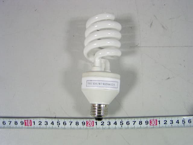
Click to zoom
Application Details
- Equipment Class
- 8CC - Part 18 Consumer Device
- Date of Grant
- Feb 22, 2007
- Application Purpose
- Original Equipment
- Date of Application
- Feb 22, 2007
- Equipment Note
- CFL
- Frequency Range
- 0.04000000 - 0.05000000
- Country
- China
Documents & Files
Document Text
Text extracted from the exhibit documents filed with the FCC. Open a document above to read the original.
Users Manual
Ionic Lite Users Manual This is a circuit for driving compact flouresent lamp (CFL) with negative ions, and the mains voltages is 120V /60Hz,and the funtions of negative ions are as belows: 1)The negative ions can effectively activate the oxygen molecule in the air and prevent air-conditioner related disease. 2)It can improve the function of the lung.When people inhale negative ions, their lung can absorb 20% more oxygen and blow off 15% more carbon ioxide. 3)It can activate many kinds of enzyme and improve metabolism. 4)It can improve people's immunity. 5)It can make people energetic,raise efficiency and improve sleep quality. 6)Small amount of ozone will be produced when the anion generator works.Associated with negative ion,the lamp can sterilize all kinds of viruses and germs. 7)It can clear the dust and smoke by neutralizing their positive electronic charge and making them fall down. 8)It can reduce television and computer's harm to people's eyes and keep television and computer from dust. 9)The hair itself has positive ions,which will absorb dusts to its surface.A great amount of static electron is produced when people comb their hair,which makes their hair stand.The negative ion can neutralize these static electon and make hair fall smoothly. Block Diagram The CFL circuit has been designed for a nominal mains voltage of 120 Vrms, 60 Hz. The circuit consists of the folwing sections,Figure 1 shows the block diagram of the circuit. Figure 1 EMI Filter AC Rectifier Start-up Circuit Half Bridge Inverter resonant circuit 120Vac 60Hz negative ions The AC mains voltage is rectified by four bridge rectifying diodes D1, D2, D3 ,D4 and two voltage-doubling capacitors C10 and C11, and then get a DC supply voltage (Vdc ,it is around 300Vdc) for the half bridge inverter. An EMI-filter formed by L1 and C1, The half bridge inverter is of the voltage fed type belonging to a group of high frequency resonant inverters, which are very attractive to drive lamp circuits. They can achieve a high efficiency, due to the ZVS2 principle, so that switching losses of the two switching transistors T1 and T2 is substantially reduced. Half Bridge Inverter The circuit is of the instant-start type to obtain almost immediate light output. When the mains voltage is applied to the circuit, the startup circuit generates a start pulse and the circuit will generate a high AC voltage across the igniter capacitor which is connected in parallel with the lamp. Normally, the lamp will breakdown and the circuit operates in the burn phase. Startup Phase After switch on of the system, the rectified mains voltage is applied to the voltage-doubling capacitors C10 and C11. The result is a high DC voltage, which is an input for the half bridge inverter (power components: Vdc-C3-E-C-F-L2-N1-T2-GND). During the startup phase, capacitor C9 is charged via the resistor R1. As soon as the voltage across C9 reaches 35 V, diac DB3 will breakdown and T2 is switched on. the half bridge midpoint voltage changes rapidly from Vdc to zero so that a positive voltage is applied to the secondary winding N3 and keeps T2 conducting. After switch-on of T2, diode D5 discharges C9 to prevent double triggering of T2. Now the circuit is oscillating and the start circuit is deactivated by diode D5. Ignition Phase After start, L2 and C5 form a series resonance circuit which is able to generate a large voltage across C5. The worst case ignition voltage for low temperatures. Burn Phase After ignition, the lamp will become low ohmic and is set to the operating point by the ballast coil L2 at a given operating frequency. Warning: This product complier with Part 18 of the FCC rules but may cause interference to televisions, radios, wireless remote control or maritime safety communications equipment or other critical navigation or communication equipment operation between 0.45-30MHz. If interference should occur, move the lamp away from the appliance a distance of three feet or more. Or plug the lamp or the compliance into a different outlet.
External Photos
External Photos SIL06-15w: EUT - Front View SIL06-15w: EUT - Back View SIL06-23w: EUT - Front View SIL06-23w: EUT - Back View SIL06-28w: EUT - Front View SIL06-28w: EUT - Back View
ID Label/Location Info
ID Label FCC ID Label FCC ID: UW7RZF061211
ID Label/Location Info
ID Label/Location Label Location Information Specifications: Text is Black or white in color and is left justified. Labels are printed in indelible ink on permanent adhesive backing or silk-screened onto the EUT or shall be affixed at a conspicuous location on the EUT. Refer to the below arrow. SIL06-15w SIL06-23w SIL06-28w
Internal Photos
Internal Photos SIL06-15w: EUT - Inside View SIL06-15w: EUT – PCB Front View SIL06-15w: EUT – PCB Rear View SIL06-23w: EUT - Inside View SIL06-23w: EUT – PCB Front View SIL06-23w: EUT – PCB Rear View SIL06-28w: EUT - Inside View SIL06-28w: EUT – PCB Front View SIL06-28w: EUT – PCB Rear View
Parts List/Tune Up Info
Quantity 15W BX 1A/250v 1 VDE127818 R5.R3 15Ω/0.25w 2 R1 270KΩ/0.5w 1 R2 390KΩ/0.25w 1 R6.R4 2.2 Ω/0.5w 2 R0 0.5mH/0.25w 1 C10.C1110uF/ 250v2 C1.C2.C3.C4.C0 104/250 v5 C7.C10.C9 223n /63 v3 C5332J /1000v1 C8 1n0 / 1000v1 DB332V 2 D1-D5 1N4007 5 D6-D9 FR107 4 T1.T2 13003 2 L2 E16 1 L1 9X10.6mH 1 L1-310*5*3 1 PCBJY241TB11 UL E199273 Panan PCB Co.Ltd Continence Daping Techology Co. Ltd Sheng Ai Electronic Co.Ltd Continence Continence Huaqiang Capacitor Electronic Co.Ltd Huaqiang Capacitor Electronic Co.Ltd Daping Techology Co. Ltd Daping Techology Co. Ltd Zi Jiang Capacitor Factory Huaqiang Capacitor Electronic Co.Ltd Yiyang Zijiang Electronic ments Co., Ltd Component List 11-07-2006 Zhengtai Electronic Co.Ltd Certificatio n NumberTypeGradeManufacturer Zhengtai Electronic Co.Ltd Zhengtai Electronic Co.Ltd San wei INC Zhengtai Electronic Co.Ltd Zhengtai Electronic Co.Ltd Quantity 23W BX 2A/250v 1 VDE127818 R5.R3 22Ω/0.25w 2 R1 270KΩ/0.5w 1 R2 390KΩ/0.25w 1 R6.R4 2.2 Ω/0.5w 2 R0 0.5mH/0.25w 1 C10.C1127uF/ 250v2 C1.C2.C3.C4.C0 104/250 v5 C7.C10.C9 223n /63 v3 C5392J /1000v1 C8 1n0 / 1000v1 DB332V 2 D1-D5 1N4007 5 D6-D9 FR107 4 T1.T2 13003 2 L2 E19 1 L1 9X10.6mH 1 L1-310*5*3 1 PCBJY241TB11 UL E199273 Panan PCB Co.Ltd Continence Daping Techology Co. Ltd Sheng Ai Electronic Co.Ltd Continence Continence Huaqiang Capacitor Electronic Co.Ltd Huaqiang Capacitor Electronic Co.Ltd Daping Techology Co. Ltd Daping Techology Co. Ltd Zi Jiang Capacitor Factory Huaqiang Capacitor Electronic Co.Ltd Yiyang Zijiang Electronic ments Co., Ltd Component List 11-07-2006 Zhengtai Electronic Co.Ltd Certificatio n NumberTypeGradeManufacturer Zhengtai Electronic Co.Ltd Zhengtai Electronic Co.Ltd San wei INC Zhengtai Electronic Co.Ltd Zhengtai Electronic Co.Ltd Quantity 28W BX 2A/250v 1 VDE127818 R5.R3 22Ω/0.25w 2 R1 270KΩ/0.5w 1 R2 390KΩ/0.25w 1 R6.R4 2.2 Ω/0.5w 2 R0 0.5mH/0.25w 1 C10.C1127uF/ 250v2 C1.C2.C3.C4.C0 104/250 v5 C7.C10.C9 223n /63 v3 C5 472J /1000v1 C8 1n0 / 1000v1 DB332V 2 D1-D5 1N4007 5 D6-D9 FR107 4 T1.T2 13005 2 L2 E19 1 L1 9X10.6mH 1 L1-310*5*3 1 PCBJY241TB11 UL E199273 Zhengtai Electronic Co.Ltd Zhengtai Electronic Co.Ltd San wei INC Zhengtai Electronic Co.Ltd Zhengtai Electronic Co.Ltd Zi Jiang Capacitor Factory Huaqiang Capacitor Electronic Co.Ltd Yiyang Zijiang Electronic ments Co., Ltd Component List 11-07-2006 Zhengtai Electronic Co.Ltd Certificatio n NumberTypeGradeManufacturer Huaqiang Capacitor Electronic Co.Ltd Huaqiang Capacitor Electronic Co.Ltd Daping Techology Co. Ltd Daping Techology Co. Ltd Panan PCB Co.Ltd Continence Daping Techology Co. Ltd Sheng Ai Electronic Co.Ltd Continence Continence
Schematics
Schematic Diagram C1 C5 C3 C9 D9 D2 D5 D7 D3 F N2 N3 N1 R3 R6 T1T2 R2 L1 C8 D8 R5 DB3 R4 C1 1C1 0 D1D4 R1 L2 15W-28W Po rtPo rt 120Vac60Hz EF C2 C0 TR
Test Report
Note: This test report is for the customer shown above and their specific product only. It may not be duplicated or used in part without prior written consent from Bay Area Compliance Laboratory Corp. (Shenzhen). This report must not be used by the customer to claim product certification, approval, or endorsement by NVLAP, NIST or any agency of the Federal Government. FCC PART 18 EMI MEASUREMENT AND TEST REPORT For ShenZhen SAST Electronic Co., Ltd. Suite1A, Building#1, NanGuang personage Garden, FuQiang Road, FuTian, ShenZhen 518000, Guangdong, China FCC ID: UW7RZF061211 This Report Concerns: Original Report Equipment Type: Ionic Lite Test Engineer: Henry Yang Report Number: RSZ06122651 Test Date: 2007-01-04 Report Date: 2007-01-12 Reviewed By: EMC Manager: Boni Baniqued Prepared By: Bay Area Compliance Laboratory Corp. (Shenzhen) 6/F, the 3rd Phase of WanLi Industrial Building, ShiHua Road, FuTian Free Trade Zone Shenzhen, Guangdong, China Tel: +86-755-33320018 Fax: +86-755-33320008 ShenZhen SAST Electronic Co., Ltd. FCC ID: UW7RZF061211 Report # RSZ06122651 Page 2 of 15 FCC Part 18 Report TABLE OF CONTENTS GENERAL INFORMATION.......................................................................................................................................3 PRODUCT DESCRIPTION FOR EQUIPMENT UNDER TEST (EUT) .....................................................................................3 OBJECTIVE...................................................................................................................................................................3 RELATED SUBMITTAL(S)/GRANT(S).............................................................................................................................3 TEST METHODOLOGY..................................................................................................................................................3 TEST FACILITY.............................................................................................................................................................3 EXTERNAL I/O CABLE..................................................................................................................................................4 SYSTEM TEST CONFIGURATION ..........................................................................................................................5 JUSTIFICATION.............................................................................................................................................................5 EQUIPMENT MODIFICATIONS.......................................................................................................................................5 CONFIGURATION OF TEST SETUP.................................................................................................................................5 BLOCK DIAGRAM OF TEST SETUP................................................................................................................................5 CONDUCTED EMISSIONS ........................................................................................................................................6 MEASUREMENT UNCERTAINTY....................................................................................................................................6 EUT SETUP..................................................................................................................................................................6 EMI TEST RECEIVER SETUP.........................................................................................................................................7 TEST EQUIPMENT LIST AND DETAILS...........................................................................................................................7 TEST PROCEDURE........................................................................................................................................................7 TEST RESULTS SUMMARY............................................................................................................................................7 TEST DATA..................................................................................................................................................................8 PLOT(S) OF TEST DATA................................................................................................................................................9 ShenZhen SAST Electronic Co., Ltd. FCC ID: UW7RZF061211 Report # RSZ06122651 Page 3 of 15 FCC Part 18 Report GENERAL INFORMATION Product Description for Equipment under Test (EUT) The ShenZhen SAST Electronic Co., Ltd.’s model: SIL06-15w; SIL06-23w; SIL06-28w or the “EUT” as referred to in this report is the CFL which measures approximately SIL06-15w: 13.5cm L x 5.5cm W x 5.5cm H, SIL06-15w: 15.0cm L x 5.5cm W x 5.5cm H, SIL06-28w: 16.5cm L x 5.5cm W x 5.5cm H, rated input voltage: AC 120V/60Hz. * The test data gathered are from production sample, serial number: 0612113, Provided by the manufacturer, we received EUT on 2006-12-26. Objective The following test report is prepared on behalf of ShenZhen SAST Electronic Co., Ltd. in accordance with Part 2, Subpart J, and Part 18, Subparts A, B and C of the Federal Communication Commissions rules and regulations. The objective of the manufacturer is to determine compliance with FCC Part 18 limits. Related Submittal(s)/Grant(s) No related submittal(s). Test Methodology All measurements contained in this report were conducted with MP-5, FCC Methods of Measurements of Radio Noise Emissions from ISM Equipment, February 1986. All measurement was performed at Bay Area Compliance Laboratory Corp. (Shenzhen). The radiated testing was performed at an antenna-to-EUT distance of 3 meters. Test Facility The Test site used by Bay Area Compliance Laboratory Corp. (Shenzhen) to collect test data is located in the 6/F, the…
Text truncated - open the document above for the full version.
Test Setup Photos
Test Setup Photos SIL06-15w: Conducted Emissions - Front View SIL06-15w: Conducted Emissions - Side View SIL06-23w: Conducted Emissions - Front View SIL06-23w: Conducted Emissions - Side View SIL06-28w: Conducted Emissions - Front View SIL06-28w: Conducted Emissions - Side View
Contact Information
Applicant
Lin Wang
Test Firm
Bay Area Compliance Laboratory Corp. (Shenzhen)John Chan
Technical Specifications
| # | Rule Parts | Frequency Range | Power Output |
|---|---|---|---|
| 1 | 18 | 0.04 MHz - 0.05 MHz | - |