UWWCONSOLE100WIRELESS BICYCLE COMPUTER
Atech Scientific Measurement Limited.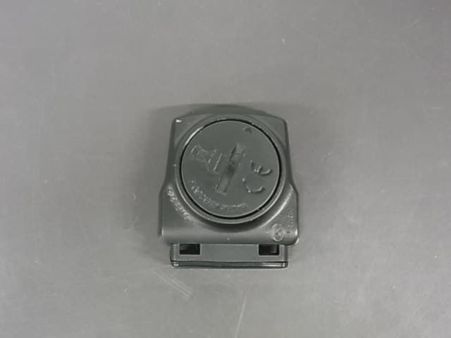
Click to zoom
Application Details
- Equipment Class
- DCD - Part 15 Low Power Transmitter Below 1705 kHz
- Date of Grant
- Jan 13, 2014
- Application Purpose
- Original Equipment
- Date of Application
- Jan 13, 2014
- Equipment Note
- WIRELESS BICYCLE COMPUTER
- Frequency Range
- 0.11070000 - 0.11070000
- Country
- Hong Kong
Documents & Files
Document Text
Text extracted from the exhibit documents filed with the FCC. Open a document above to read the original.
External Photos
External Photo
Internal Photos
Internal Photo
Operational Description
Operation Description Console 100 is operated by a 3V button cell. The oscillator operates when magnet getting close to the reed switch sensor. The oscillator works with LC network and amplifier transistor. A 110kHz RF signal is transmitted once via a ferrite bar antenna with specified interval which controlled by parameter of circuitry. This transmitter transmits an ON-OFF Keying modulation to receiver. Circuit composition 1. Switch Reed switch 2. RF circuit T3, L1, L2
Test Report
TEST REPORT Report No. : AR0066921(2) Date : 27 Nov 2013 For and on behalf of CMA Industrial Development Foundation Limited Authorized Signature : Page 1 of 32 Mr. WONG Lap-pong, Andrew Assistant Manager Electrical Division FCC ID: UWWCONSOLE100 Application No. : LR033775(3) Applicant : Atech Scientific Measurement Limited Unit A-C, 18F., Luk Hop Ind. Bldg. 8 Luk Hop Street San Po Kong, Kowloon Client : EASTON BELL SPORTS (ASIA) LTD SUITE 1003 SKYLINE TOWER, 39 WANG KWONG KOWLOON BAY, KOWLOON Sample Description : One(1) item of submitted sample stated to be Wireless bicycle computer - Console 100 of Model No. BCAC0667 Sample registration No. : RR036985-002 Radio Frequency : 110.72 kHz Transmitter Rating : 1 x 3V button cell No. of submitted sample : Three (3) set (s) Date Received : 04 Sep 2013 Test Period : 24 Sep 2013 to 26 Nov 2013. Test Requested : FCC Part 15 Certificate Test Method : 47 CFR Part 15 (10-1-12 Edition), ANSI C63. 4 – 2009 Test Engineer : Mr. LEUNG Shu-kan, Ken Test Result : See attached sheet(s) from page 2 to 32. Conclusion : The submitted sample was found to comply with requirement of FCC Part 15 Subpart C. TEST REPORT Report No. : AR0066921(2) Date : 27 Nov 2013 Page 2 of 32 FCC ID: UWWCONSOLE100 Table of Contents 1 General Information ................................................................................................................................... 3 1.1 General Description ............................................................................................................................ 3 1.2 Location of the test site ....................................................................................................................... 4 1.3 List of measuring equipment............................................................................................................... 5 1.4 Measurement Uncertainty ................................................................................................................... 6 2 Description of the radiated emission test ................................................................................................... 7 2.1 Test Procedure .................................................................................................................................... 7 2.2 Test Result .......................................................................................................................................... 8 2.3 Radiated Emission Measurement Data ............................................................................................... 9 3 Description of the Line-conducted Test ................................................................................................... 10 3.1 Test Procedure .................................................................................................................................. 10 3.2 Test Result ........................................................................................................................................ 10 3.3 Graph and Table of Conducted Emission Measurement Data .......................................................... 10 4 Photograph ...............................................................................................................................................11 4.1 Photographs of the Test Setup for Radiated Emission and Conducted Emission ............................. 11 4.2 Photographs of the External and Internal Configurations of the EUT.............................................. 11 5 Supplementary document ......................................................................................................................... 12 5.1 Bandwidth ......................................................................................................................................... 12 5.2 Duty cycle ......................................................................................................................................... 12 5.3 Transmission time ............................................................................................................................. 12 5.4 Power Spectral Density..................................................................................................................... 12 5.5 Average on time ................................................................................................................................ 12 6 Appendices...............................................................................................................................................13 TEST REPORT Report No. : AR0066921(2) Date : 27 Nov 2013 Page 3 of 32 FCC ID: UWWCONSOLE100 1 General Information 1.1 General Description The equipment under test (EUT) is a transmitter. It operates at 110.72 kHz and the oscillation of radio control is generated by a LRC circuit. The EUT is powered by 1 x 3V button cell. The oscillator operates when magnet getting close to the reed switch sensor. The oscillator works with LC network and amplifier. RF signal is transmitted once via a ferrite bar antenna to receiver. The antenna / antenna terminal is permanently attached in EUT and the radio output power is unable to adjust. The brief circuit description is listed as follows: - Reed Switch and its associated circuit act as switch - T3, L1, L2 and its associated circuit act as RF circuit TEST REPORT Report No. : AR0066921(2) Date : 27 Nov 2013 Page 4 of 32 FCC ID: UWWCONSOLE100 1.2 Location of the test site FCC Registered Test Site Number: 552221 Radiated emissions measurements are investigated and taken pursuant to the procedures of ANSI C63.4 – 2009. A Semi-Anechoic Chamber Testing Site is set up for investigation and located at: Ground Floor, Yan Hing Centre, 9 – 13 Wong Chuk Yeung Street, Fo Tan, Shatin, New Territories, Hong Kong. Conducted emissions measurements are investigated and also taken pursuant to the procedures of ANSI C63.4 – 2009…
Text truncated - open the document above for the full version.
Test Report
TEST REPORT Report No. : AR0066921(2) Date : 27 Nov 2013 Tested by: Reviewed by: Mr. LEUNG Shu-kan, Ken Mr. WONG Lap-pong, Andrew Page 19 of 32 FCC ID: UWWCONSOLE100 A5. Bandwidth Plot Bandwidth 1
Test Setup Photos
Test Set Up 9kHz – 30MHz (Front view) 9kHz – 30MHz (Back view) 30MHz – 1GHz (Front view) 30MHz – 1GHz (Back View)
Contact Information
Applicant
Jamson Cheng(Sales Manager)
Test Firm
CMA Industrial Development Foundation LimitedJoey Kwok
[email protected]+852 2690 8255
Technical Specifications
| # | Rule Parts | Frequency Range | Power Output |
|---|---|---|---|
| 1 | 15C | 0.1107 MHz - 0.1107 MHz | - |
Other Applications from Atech Scientific Measurement Limited.

UWW-WS
Feb 15, 2007Wireless Digital Thermometer
Equipment Class
DSC - Part 15 Security/Remote Control Transmitter