UXEMWSSTSR2MICROWAVE SENSORS, MODEL: MWS-ST-2 AND MWS-SR-2
Wire Automatic Device Co., Ltd.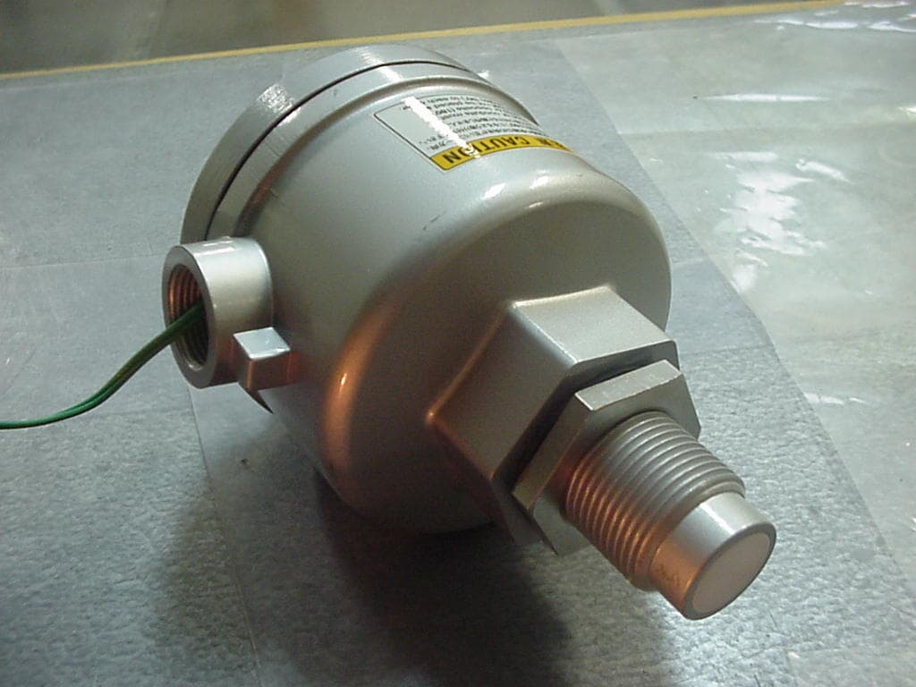
Click to zoom
Application Details
- Equipment Class
- FDS - Part 15 Field Disturbance Sensor
- Date of Grant
- Feb 14, 2007
- Application Purpose
- Original Equipment
- Date of Application
- Feb 13, 2007
- Equipment Note
- MICROWAVE SENSORS, MODEL: MWS-ST-2 AND MWS-SR-2
- Frequency Range
- 24.15300000 - 24.15300000
- Country
- Japan
Documents & Files
Document Text
Text extracted from the exhibit documents filed with the FCC. Open a document above to read the original.
Users Manual
FCC ID: UXEMWSSTSR2 Report No. M060937_Cert_MWS_ST_SR EMC Technologies Pty Ltd – 57 Assembly Drive, Tullamarine VIC 3043 Australia www.emctech.com.au EMC Technologies Report Number: M060937_Cert_MWS_ST_SR APPENDIX G USER MANUAL 1 WADECO MICROWAVE LEVEL SWITCH MWS-ST/SR-2 DELUXE MODEL MICROWAVE LEVEL SWITCH OPERATION MANUAL MWS MWSMWS MWS- -- -ST/SR ST/SRST/SR ST/SR- -- -2 DELUXE 2 DELUXE 2 DELUXE 2 DELUXE SERIES SERIESSERIES SERIES DELUXE MODEL MWS-ST-2 [TRANSMITTER] MWS-SR-2 [TRANSCEIVER] 2 WADECO MICROWAVE LEVEL SWITCH MWS-ST/SR-2 DELUXE MODEL TABLE of CONTENTS OPERATION PRINCIPAL...... 3 FEATURES........................ 4 SPECIFICATIONS............... 5 APPLICATIONS.................. 6 HARDWARE OPTIONS........ 9 DIMENSIONS & PART NUMBERS......................... 11 INSTALLATION & MOUNTING........................ 13 WIRING............................. 16 FUNCTION OF SWITCHES, INDICATORS AND RHEOSTATS...................... 18 SENSITIVITY ADJUSTMENT.................... 19 GUARANTEE..................... 20 FCC Modification Warning Any changes or modifications not expressively approved by WADECO LTD. could void the user's authority to operate this equipment. NOTE: This equipment has been tested and found to comply with the limits for a Class B digital device, pursuant to Part 15 of the FCC Rules. These limits are designed to provide reasonable protection against harmful interference in a residential installation. This equipment generates, uses and can radiate radio frequency energy and, if not installed and used in accordance with the instructions, may cause harmful interference to radio communications. However, there is no guarantee that interference will not occur in a particular installation. If this equipment does cause harmful interference to radio or television reception, which can be determined by turning the equipment off and on, the user is encouraged to try to correct the interference by one or more of the following measures: • Reorient or relocate the receiving antenna, • Increase the separation between the equipment and receiver, • Connect the equipment into an outlet on a circuit different from that to which the receiver is connected, • Consult the dealer or an experienced radio/TV technician for help. 3 WADECO MICROWAVE LEVEL SWITCH MWS-ST/SR-2 DELUXE MODEL OPERATION PRINCIPAL General The MWS- ST/SR type microwave sensor is a level switch consisting of a transmitter (MWS-ST-2) and a transceiver (MWS-SR-2) installed face-to-face. The transmitter emits a continuous, low power microwave beam towards the transceiver and an output relay is released when the beam is obstructed. The sensor has wide application across all areas of industry where highly reliable, non- contact level detection is required . The sensor is generally used for process control by monitoring presence/absence of product, flow/no flow conditions and point level detection in bins and silos. The sensor may also be used as a proximity switch for detection of vehicles such as dump trucks and rail cars. Penetrability of Microwaves Harsh environments may result in a buildup of contaminants on the sensing head; however, the sensor is easily able to penetrate such buildup thanks to the high penetrability of microwaves. When microwaves transmitted through air encounter an object, some will be reflected, some absorbed and the rest will pass through the object. The amount of microwaves passing through the object depends on its composition. Generally speaking, microwaves cannot penetrate metals and are reflected; water absorbs the most microwaves. Microwaves can easily pass through plastics, glass, ceramic, paper etc. Safety of Microwaves The sensor’ s output is regulated to assure compliance with FCC Rule 15, covering field disturbance devices. With low output power, the sensor’s power is well below the American OSHA exposure specifications as stated in Section 1910.97. There are no health hazards to personnel operating WADECO sensors: no license, approval or caution sign posting is required. Heterodyne vs. Diode Detection The MWS- ST/SR level switch is the first of its kind to utilize the heterodyne detection method rather than the, now obsolete, diode detection method. Received power level Detection output Heterodyne method (WADECO) Noise level Diode method (commonly used) Minimum received power: -70dBm Minimum received power: -50dBm The heterodyne detection method gives detection output that is proportional to the received power level, whereas the diode detection method gives detection output that is proportional to the square of the received power level. Therefore the heterodyne method allows detection with a minimum received power that is lower than that of the minimum level required by the diode detection method. This greatly increases the operating range/penetrability without any increase in the power of the transmitted microwave radiation. 4 WADECO MICROWAVE LEVEL SWITCH MWS-ST/SR-2 DELUXE MODEL FEATURES 100m Range with heterodyne detection Approx. 100m range with a Ø27mm antenna, thanks to the Heterodyne detection method. High penetration Easily penetrates process buildup on antenna, firebrick, refractory etc., thanks to the increased operating range. Unaffected by adverse environments The sensor is unaffected by surface contaminants, flames, steam, vapor or airborne particles. Simple beam alignment Easy initial beam alignment at installation, thanks to the wide beam angle. Selectable detection mode Either broken beam (BLOCK) or unbroken beam (UNBLOCK) detection method may be selected. On delay time rheostat On delay time, adjustable 0.1~10secs., prevents instantaneous detection of falling material whist filling. 15 LED indicator bank A 15 LED indicator array displays the received power level and the sensitivity- set- point, allowing for visual sensitivity adjustment and maintenance. No set-to-set interference Four channels are availabl e (CH1~4), selectable by rotary switch, eliminating set- to-set i nterference…
Text truncated - open the document above for the full version.
Cover Letter(s)
Sensors for the 21 Sensors for the 21Sensors for the 21 Sensors for the 21 st stst st Century Century Century Century Wire Automatic Device Co., Ltd. 1-9-27, Jokoji, Amagasaki-shi, Hyogo-ken 660-0811, Japan TEL: 81-6-6482-3838 FAX: 81-6-6481-6321 Web: http://www.wadeco.co.jp Mailto: [email protected] Federal Communications Commission Authorization and Evaluation Division Confidentiality Request regarding application for certification of FCC ID: UXEMWSSTSR2. Pursuant to Sections 0.457 and 0.459 of the Commission’s Rules, we hereby request confidential treatment of information accompanying this application as outlined below: Exhibit Type File Name Operational Description Block Diagram Schematics Appendix C Operational Description.pdf Appendix D Block Diagram.pdf Appendix E Schematics.pdf The above materials contain trade secrets and proprietary information not customarily released to the public. The public disclosure of these materials may be harmful to the applicant and provide unjustified benefits to its competitors. The applicant understands that pursuant to Section 0.457 of the Rules, disclosure of this application and all accompanying documentation will not be made before the date of the Grant for this application. Sincerely, Michael Hartnett International Sales and Marketing Manager Wire Automatic Device Co., Ltd. (WADECO Ltd.) 1-9-27 Jokoji, Amagasaki-shi, Hyogo-ken 660-0811, JAPAN. Tel: +81-6-6482-3838, Fax: +81-6-6481-6321 International Mobile: +81-80-3114-9356 Mobile Email: [email protected] Email: [email protected] Web: http://www.wadeco.co.jp
Cover Letter(s)
EMC Technologies Pty Ltd, 57 Assembly Drive, Tullamarine VIC 3043 Australia Ph: +613 9335 3333 Fax: +613 9338 9260 www.emctech.com.au EMC Technologies Pty Ltd ABN 82 057 105 549 57 Assembly Drive Tullamarine Victoria Australia 3043 Ph: + 613 9335 3333 Fax: + 613 9338 9260 email: [email protected] To: TIMCO Engineering Inc. Attention: Certification Manager No. of pages: 1 From: Donna Lennon Date: 25 th January 2007 EMC Ref: M060937_Cert_MWS_ST_SR Subject: FCC APPROVAL – FCC ID: UXEMWSSTSR2 Please receive EMC Technologies’ Report M060937_Cert_MWS_ST_SR for review. The EUT is a Microwave Sensors, Model: MWS-ST-2 and MWS-SR-2. Test results are recorded as follows: Documents submitted: EMC Technologies Report – M060937_Cert_MWS_ST_SR Test results - FCC Part 15.245 Required FCC Forms: Agent Authority, Confidentiality Request and Form 731 EMC Technologies Pty Ltd is acting as agent for WADECO Ltd during this product approval. Their corresponding FRN is 0015954506 The FCC ID for this application is FCC ID: UXEMWSSTSR2 Regards _____________ Donna Lennon Report Secretary EMC Technologies Pty Ltd
External Photos
FCC ID: UXEMWSSTSR2 Report No. M060937_Cert_MWS_ST_SR EMC Technologies Pty Ltd – 57 Assembly Drive, Tullamarine VIC 3043 Australia www.emctech.com.au EMC Technologies Report Number: M060937_Cert_MWS_ST_SR APPENDIX B1 TEST SAMPLE PHOTOS - EXTERNAL FCC ID: UXEMWSSTSR2 Report No. M060937_Cert_MWS_ST_SR EMC Technologies Pty Ltd – 57 Assembly Drive, Tullamarine VIC 3043 Australia www.emctech.com.au MWS-ST-2 and MWS-SR-2
ID Label/Location Info
FCC ID: UXEMWSSTSR2 Report No. M060937_Cert_MWS_ST_SR EMC Technologies Pty Ltd – 57 Assembly Drive, Tullamarine VIC 3043 Australia www.emctech.com.au EMC Technologies Report Number: M060937_Cert_MWS_ST_SR APPENDIX F FCC LABELLING DETAILS
Internal Photos
FCC ID: UXEMSWSTSR2 Report No. M060937_Cert_MWS_ST_SR EMC Technologies Pty Ltd – 57 Assembly Drive, Tullamarine VIC 3043 Australia www.emctech.com.au MWS-ST-2 FCC ID: UXEMSWSTSR2 Report No. M060937_Cert_MWS_ST_SR EMC Technologies Pty Ltd – 57 Assembly Drive, Tullamarine VIC 3043 Australia www.emctech.com.au MWS-ST-2 TRANSMITTER – DOPPLER MODULE PHOTOS
Test Report
TIMCO ENGINEERING INC. 849 NW State Road 45 Newberry, Florida 32669 http://www.timcoengr.com 888.472.2424 F 352.472.2030 email: [email protected] APPLICANT: WIRE AUTOMATIC DEVICE CO., LTD. FCC PART 15 SUBPART 15.245 TEST REPORT APPLICANT WIRE AUTOMATIC DEVICE CO., LTD. 1-9-27, JOKOJI, AMAGASAKI-SHI, HYOGO-KEN 660-0811 JAPAN TEL FCC ID: UXEMWS-SR-2 PRODUCT DESCRIPTION MICROWAVE SWITCH DATE SAMPLE RECEIVED January 25, 2006 DATE TESTED February 1, 2007 TESTED BY Richard Block APPROVED BY Mario de Aranzeta TIMCO REPORT NO. W\WADECO_UXE\200UT7\200UT7TestReport.doc TEST RESULTS PASS FAIL THE ATTACHED REPORT SHALL NOT BE REPRODUCED EXCEPT IN FULL WITHOUT THE WRITTEN APPROVAL OF TIMCO ENGINEERING, INC. FCC ID: UXEMWS-SR-2 REPORT #: W\WADECO_UXE\200UT7\200UT7TestReport.doc COVER SHEET TIMCO ENGINEERING INC. 849 NW State Road 45 Newberry, Florida 32669 http://www.timcoengr.com 8.472.2424 F 352.472.2030 email: [email protected] 88 APPLICANT: WIRE AUTOMATIC DEVICE CO., LTD. FCC ID: UXEMWS-SR-2 REPORT #: W\WADECO_UXE\200UT7\200UT7TestReport.doc TABLE OF CONTENTS TABLE OF CONTENTS APPLICANT: WIRE AUTOMATIC DEVICE CO., LTD. FCC ID: UXEMWS-SR-2 TEST REPORT CONTAINING: PAGE 1............TEST EQUIPMENT LIST & TEST PROCEDURE PAGE 2............TEST PROCEDURE CONTD. PAGE 3-4..........RADIATION INTERFERENCE TEST DATA PAGE 5............TEST SETUP PHOTO PAGE 6 OCCUPIED BANDWIDTH PAGE 7............OCCUPIED BANDWIDTH PLOTS TIMCO ENGINEERING INC. 849 NW State Road 45 Newberry, Florida 32669 http://www.timcoengr.com 888.472.2424 F 352.472.2030 email: [email protected] APPLICANT: WIRE AUTOMATIC DEVICE CO., LTD. EMC Equipment List Device Manufacturer Model Serial Number Cal/Char Date Due Date 3/10-Meter OATS TEI N/A N/A Listed 3/27/04 3/26/07 3-Meter Anechoic Chamber TEI N/A N/A Listed 5/11/04 5/11/07 Antenna: Biconnical Eaton 94455-1 1057 CAL 12/12/05 12/12/07 Antenna: Biconnical Eaton 94455-1 1096 CAL 10/11/06 10/11/08 Antenna: Biconnical Electro-Metrics BIA-25 1171 CAL 4/29/05 4/29/07 Analyzer Gray Tower Quasi- Peak Adapter Agilent 85650A 2811A01279 CAL 4/13/05 4/13/07 Analyzer Gray Tower RF Preselector Agilent 85685A 2926A00983 CAL 9/5/05 9/5/07 Analyzer Gray Tower Spectrum Analyzer Agilent 8566B 2928A04729 2848A18049 CAL 4/13/05 4/13/07 LISN Electro-Metrics ANS-25/2 2604 CAL 10/5/06 10/5/08 LISN Electro-Metrics EM-7820 2682 CAL 4/28/05 4/28/07 Antenna: Log- Periodic Eaton 96005 1243 CAL 12/14/05 12/14/07 Mixer Agilent 11970A,K,Q various 12/12/06 12/12/08 DR Horn ETS 3117 ETS-1 12/30/06 12/30/08 Mixer Oleson Microwave M12HWA M08HWA E30425-1 12/12/06 12/12/08 Antennas Std Gain Oleson Microwave 40-60 GHz 60-90 GHz 90-110 GHz various N/A N/A Spectrum Receiver R& S ESIB-40 100274 11/25/05 11/25/07 FCC ID: UXEMWS-SR-2 REPORT #: W\WADECO_UXE\200UT7\200UT7TestReport.doc Page 1 of 7 TIMCO ENGINEERING INC. 849 NW State Road 45 Newberry, Florida 32669 http://www.timcoengr.com 888.472.2424 F 352.472.2030 email: [email protected] APPLICANT: WIRE AUTOMATIC DEVICE CO., LTD. TEST PROCEDURE RADIATION INTERFERENCE: The test procedure used was ANSI C63.4-2003 using a Agilent spectrum analyzer with a preselector. The analyzer was calibrated in dB above a microvolt at the output of the antenna. The resolution bandwidth was 100 kHz and the video bandwidth was 300 kHz up to 1.0 GHz and 1.0 MHz with a video BW of 1.0 MHz above 1.0 GHz. The ambient temperature of the DUT was 78° F with a humidity of 40%. FORMULA OF CONVERSION FACTORS: The field strength at 3m was established by adding the meter reading of the spectrum analyzer (which is set to read in units of dBuV) to the antenna correction factor supplied by the antenna manufacturer. The antenna correction factors are stated in terms of dB/m. The gain of the preselector was accounted for in the spectrum analyzer meter reading. Example: Freq (MHz) METER READING + ACF = FS 33 20 dBuV + 10.36 dB = 30.36 dBuV/m @ 3m ANSI C63.4-2003 10.1.7 MEASUREMENT PROCEDURES: The DUT was placed on a table 80 cm high and with dimensions of 1m by 1.5m. The DUT was placed in the center of the table (1.5m side). The table used for radiated measurements is capable of continuous rotation. When an emission was found, the table was rotated to produce the maximum signal strength. At this point, the antenna was raised and lowered from 1 m to 4 m. The antenna was placed in both the horizontal and vertical planes. FCC ID: UXEMWS-SR-2 REPORT #: W\WADECO_UXE\200UT7\200UT7TestReport.doc Page 2 of 7 TIMCO ENGINEERING INC. 849 NW State Road 45 Newberry, Florida 32669 http://www.timcoengr.com 888.472.2424 F 352.472.2030 email: [email protected] APPLICANT: WIRE AUTOMATIC DEVICE CO., LTD. APPLICANT: WIRE AUTOMATIC DEVICE CO., LTD. FCC ID: UXEMWS-SR-2 NAME OF TEST: RADIATION INTERFERENCE RULES PART NUMBER: 15.245, 15.209 REQUIREMENTS: Field Strength of Fundamental Field Strength of Harmonics 24075- 24175 MHz 127.96 dBuV/m @3 meters 87.96 dBuV/m @3 meters EMISSIONS RADIATED OUTSIDE OF THE SPECIFIED FREQUENCY BANDS, EXCEPT FOR HARMONICS, SHALL BE ATTENUATED BY AT LEAST 50 dB BELOW THE LEVEL OF THE FUNDAMENTAL OR TO THE GENERAL RADIATED EMISSION LIMITS IN 15.209, WHICHEVER IS THE LESSER ATTENUATION. TEST DATA: Tuned Frequency GHz Emission Frequency GHz Meter Reading dBuV Ant. Polarity V/H Correction Factor dB/m Field Strength dBuV/m Margin dB 24.153 24.153 111.85 H 8.35 120.2 17.76 24.153 48.306 49.4 H 40.39 89.79 8.17 24.153 72.459 42.9 H 47.8 90.7 7.26 Tuned Frequency GHz Emission Frequency GHz Meter Reading dBuV Ant. Polarity V/H Correction Factor dB/m Field Strength dBuV/m Margin dB 24.111 24.111 117.17 H 8.35 125.52 12.44 24.111 48.222 37.5 H 40.39 77.89 20.07 24.111 72.333 47.3 H 47.8 95.1 2.86 The fundamental was measured at a 3 meters distance and the harmonics measured at 1 meter distance. The table above shows a 3 meter to 1 meter correction factor of 10 dB for the harmonics. FCC ID: UXEMWS-SR-2 REPORT #: W\WADECO_UXE\200UT7\200UT7TestReport.doc Page 3 of 7 TIMCO ENGINEERING INC. 849 NW State Road 45 Newberry, Flori…
Text truncated - open the document above for the full version.
Test Report
FCC ID: UXEMWSSTSR2 Report No. M060937_Cert_MWS_ST_SR EMC Technologies Pty Ltd – 57 Assembly Drive, Tullamarine VIC 3043 Australia www.emctech.com.au EMC Technologies Report Number: M060937_Cert_MWS_ST_SR APPENDIX A MEASUREMENT INSTRUMENTATION DETAILS EQUIPMENT TYPE MAKE/MODEL SERIAL NUMBER LAST CAL. DD/MM/YY DUE DATE DD/MM/YY CAL. INTERVAL EMI RECEIVER Rohde & Schwarz, Model ESIB40 SN 1088 7490, 20 Hz – 40 GHz 22/06/06 22/06/07 1 YEAR *2 HP 8546A Sn.3549A00290 04/04/06 04/04/07 1 YEAR *4 ANTENNAS EMCO 3115 DOUBLE RIDGED HORN 1 - 18 GHz Sn: 8908-3282 24/02/06 24/02/09 3 YEAR *1 EMCO 3116 Double Ridged Guide Horn 18 - 40 GHz Sn: 2276 -------- -------- *3 ETS Standard Gain Horn, M/N: 3160-03 25/06/04 25/06/07 3 YEAR *1 ETS Standard Gain Horn, M/N: 3160-04 28/10/03 28/10/06 3 YEAR *1 Narda Standard Gain Horn, M/N: 644 25/06/04 25/06/07 3 YEAR *1 ETS Standard Gain Horn, M/N: 3160-06 25/06/04 25/06/07 3 YEAR *1 ETS Standard Gain Horn, M/N: 3160-07 25/06/04 25/06/07 3 YEAR *1 ETS Standard Gain Horn, M/N: 3160-08 25/06/04 25/06/07 3 YEAR *1 EMCO 93110B BICONICAL 24/06/06 24/06/07 1 YEAR *1 20 – 300 MHz Sn: 9803-3077 EMCO 93146 LOG PERIODIC 15/06/06 15/06/07 1 YEAR *1 200 -1000MHz Sn: 9807-5112 LISN EMCO 3825/2 Sn 9607-2567 16/05/06 16/05/07 1 YEAR *1 Note *1. In-house calibration. Refer to Quality Manual. Note *2. NATA calibration by Vicom Note *3. Manufacturer’s Calibration Note *4. NATA calibration by Agilent Technologies (Aust) Pty Ltd TEST SITES Shielded Room Test Laboratory Melbourne 11m x 8m x 4m Chamber-semi-anechoic 8.8m x 5.8m x 3.1m Test Chamber 3.4m x 6.1m x 2.5m Test Chamber 3.4m x 7.3m x 7.5m Test Chamber Jan 06 N/A N/A N/A Jan 07 N/A N/A N/A 1 YEAR *1 N/A N/A N/A Open Area Test Site Melbourne 3/10 Metre site. 1-4 metre antenna mast. 1.2 metre/400 kg Turntable. (Situated at Lerderderg Gorge, near Bacchus Marsh, Victoria) 11/02/06 11/02/07 1 YEAR *1 Note *1. In-house calibration. Refer to Quality Manual.
Test Report
FCC ID: UXEMWSSTSR2 Report No. M060937_Cert_MWS_ST_SR EMC Technologies Pty Ltd – 57 Assembly Drive, Tullamarine VIC 3043 Australia www.emctech.com.au EMC Technologies Report Number: M060937_Cert_MWS_ST_SR APPENDIX H GRAPHS OF EMI MEASUREMENT EMC Technologies Pty. Ltd. - Global Product Certification Job No:m060937 Test Date: 24-11-06 GRAPH No. 1 p:\PCF\M060937_1.PCF EMC Technologies (Melbourne) 57 Assembly Drv Tullamarine, 3043, Vic, Australia Phone+(613) 9335 3333 Fax+(613) 9338 9260 WADECO Ltd Microwave Sensors MWS-ST-2 and MWS-SR-2 Conducted Emissions - Active Line Conducted Emissions (dBuV) m060937c Limits: Legend: Source: _ FCC_BQPN FCC PART 15 CLASS B CONDUCTED QP LIMITS (2002) _ FCC_BAVN FCC PART 15 CLASS B CONDUCTED AVERAGE LIMIT (2002) __ Active Line 1 2 6 Ver 0.55 Build 146conducted lab 1 using L- 22 LISN t:L0220507 c1:C1450207 c2:C1600807 p:NONE a:L0180707Site ID: Room#3,57 Assembly Drv. Tullamarine, VIC Test Officer:Ann Stevens Frequency (MHz) 1 10 .15 30 10 20 30 40 50 60 70 EMC Technologies Pty. Ltd. - Global Product Certification Job No:m060937 Test Date: 24-11-06 GRAPH No. 2 p:\PCF\M060937_2.PCF EMC Technologies (Melbourne) 57 Assembly Drv Tullamarine, 3043, Vic, Australia Phone+(613) 9335 3333 Fax+(613) 9338 9260 WADECO Ltd Microwave Sensors MWS-ST-2 and MWS-SR-2 Conducted Emissions - Neutral Line Conducted Emissions (dBuV) m060937c Limits: Legend: Source: _ FCC_BQPN FCC PART 15 CLASS B CONDUCTED QP LIMITS (2002) _ FCC_BAVN FCC PART 15 CLASS B CONDUCTED AVERAGE LIMIT (2002) __ Neutral Line 3 4 5 Ver 0.55 Build 146conducted lab 1 using L- 22 LISN t:L0220507 c1:C1450207 c2:C1600807 p:NONE a:L0180707Site ID: Room#3,57 Assembly Drv. Tullamarine, VIC Test Officer:Ann Stevens Frequency (MHz) 1 10 .15 30 10 20 30 40 50 60 70 EMC Technologies Pty. Ltd. - Global Product Certification Job No:m060937 Test Date: 12-10-06 GRAPH No. 3 p:\PCF\m060937_3.PCF EMC Technologies (Melbourne) 57 Assembly Drv Tullamarine, 3043, Vic, Australia Phone+(613) 9335 3333 Fax+(613) 9338 9260 WADECO Ltd Microwave Sensors MWS-ST-2 and MWS-SR-2 Radiated Emissions - Vertical Polarity Radiated Emissions (dBuV/m) m060937r # = Ambient Limits: Legend: Source: _ FCCB-10 FCC CLASS B RAD 10M LIMITS __ Vertical Emissions 8 9 10 11 12 4 6 7 Ver 0.55 Build 146radiated emissions site 1 lerderderg t:A1360607_10M c1:C1311206 c2:NONE p:NONE a:NONESite ID: OATS1,Lerderderg Gorge Rd, Bacchus Marsh, VIC Test Officer:Kevin Hansen Peaks:No Freq Peak QP Val FCCB-10 dL1 (MHz) (dBuV/m) (dBuV/m) (dB) 1 60.01 26.5 25.6 29.5 -3.9 2 55.03 25.7 24.3 29.5 -5.2 3 80.01 24.4 23.9 29.5 -5.6 4 40.02 22.6 21.4 29.5 -8.1 Frequency (MHz) 100 29.8 1001 10 20 30 40 50 60 70 v ^ 1 ~ v ^ 2 ~ v ^ 3 ~ v ^ 4 ~ # # # # # # # # # # # # # # # # # # # # # # # # # # # # # # # # # # # # # # # # # # # # # # # # # # # # # # # # # # # # # # # # # # # # # # # # # # # # # # # # # # # # # # # # # # # # # # # # # # # # # # # # # # # # # # # # # # # # # # # # # # # # # # # # # # # # # # # # # # # # # # # # # # # # # # # # # # # # # # # # # # # # # # # # # # # # # # # # # # # # # # # # # # # # # # # # # # # # # # # # # # # # # # # # # # # # # # # # # # # EMC Technologies Pty. Ltd. - Global Product Certification Job No:m060937 Test Date: 12-10-06 GRAPH No. 4 p:\PCF\m060937_4.PCF EMC Technologies (Melbourne) 57 Assembly Drv Tullamarine, 3043, Vic, Australia Phone+(613) 9335 3333 Fax+(613) 9338 9260 WADECO Ltd Microwave Sensors MWS-ST-2 and MWS-SR-2 Radiated Emissions - Horizontal Polarity Radiated Emissions (dBuV/m) m060937r # = Ambient Limits: Legend: Source: _ FCCB-10 FCC CLASS B RAD 10M LIMITS __ Horizontal Emissions 13 14 15 16 17 1 2 3 Ver 0.55 Build 146radiated emissions site 1 lerderderg t:A1360607_10M c1:C1311206 c2:NONE p:NONE a:NONESite ID: OATS1,Lerderderg Gorge Rd, Bacchus Marsh, VIC Test Officer:Kevin Hansen Peaks:No Freq Peak QP Val FCCB-10 dL1 (MHz) (dBuV/m) (dBuV/m) (dB) 1 72.80 19.5 11.7 29.5 -17.9 2 46.86 19.3 10.8 29.5 -18.7 3 86.04 18.8 10.6 29.5 -18.9 Frequency (MHz) 100 29.8 1001 10 20 30 40 50 60 70 v ^ 1 ~ v ^ 2 ~ v ^ 3 ~ # # # # # # # # # # # # # # # # # # # # # # # # # # # # # # # # # # # # # # # # # # # # # # # # # # # # # # # # # # # # # # # # # # # # # # # # # # # # # # # # # # # # # # # # # # # # # # # # # # # # # # # # # # # # # # # # # # # # # # # # # # # # # # # # # # # # # # # # # # # # # # # # # # # # # # # # # # # # # # # # # # # # # # # # # # # # # # # # # # # # # # # # # # # # # # # # # # # # # #
Test Report
FCC ID: UXEMWSSTSR2 Report No. M060937_Cert_MWS_ST_SR EMC Technologies Pty Ltd – 57 Assembly Drive, Tullamarine VIC 3043 Australia www.emctech.com.au EMC Technologies Report Number: M060937_Cert_MWS_ST_SR APPENDIX I BANDEDGE Bandedge – Low Bandedge - High
Test Report
Page 1 of 11 EMI TEST REPORT FOR CERTIFICATION to FCC PART 15 Subpart C (Section 15.245) FCC ID: UXEMWSSTSR2 Test Samples: Microwave Sensors Model Numbers: MWS-ST-2 and MWS-SR-2 Report Number M060937_Cert_MWS_ST_SR Tested for: WADECO Ltd Issue Date: 19 th January 2006 EMC Technologies Pty Ltd reports apply only to the specific samples tested under stated test conditions. It is the manufacturer’s responsibility to assure that additional production units of this model are manufactured with identical electrical and mechanical components. EMC Technologies Pty Ltd shall have no liability for any deductions, inferences or generalisations drawn by the client or others from EMC Technologies Pty Ltd issued reports. This report shall not be used to claim, constitute or imply product endorsement by EMC Technologies Pty Ltd. The tests, calibrations or measurements covered by this document have been performed in accordance with NATA requirements which include the requirements of ISO/IEC 17025 and are traceable to national standards of measurement. This document shall not be reproduced, except in full. EMC Technologies Pty Ltd ABN 82 057 105 549 57 Assembly Drive Tullamarine Victoria Australia 3043 Ph: + 613 9335 3333 Fax: + 613 9338 9260 email: [email protected] FCC ID: UXEMWSSTSR2 Report No. M060937_Cert_MWS_ST_SR Page 2 of 11 The tests reported herein have been performed in accordance with its terms of accreditation for FCC Part 15.This document shall not be reproduced, except in full. EMI TEST REPORT FOR CERTIFICATION to FCC PART 15 Subpart C (Section 15.245) EMC Technologies Report No. M060937_Cert_MWS_ST_SR Issue Date: 19 th January 2006 CONTENTS 1.0 INTRODUCTION 2.0 GENERAL INFORMATION 3.0 CONDUCTED EMI MEASUREMENTS 4.0 RADIATED EMI MEASUREMENTS 5.0 ANTENNA REQUIREMENT 6.0 COMPLIANCE STATEMENT APPENDIX A: MEASUREMENT INSTRUMENT DETAILS APPENDIX B: REPORT PHOTOGRAPHS APPENDIX C: OPERATIONAL DESCRIPTION APPENDIX D: BLOCK DIAGRAM APPENDIX E: SCHEMATICS APPENDIX F: FCC LABELLING DETAILS APPENDIX G: USER MANUAL APPENDIX H: GRAPHS of EMI MEASUREMENTS APPENDIX I: BANDEDGE PLOTS FCC ID: UXEMWSSTSR2 Report No. M060937_Cert_MWS_ST_SR Page 3 of 11 The tests reported herein have been performed in accordance with its terms of accreditation for FCC Part 15.This document shall not be reproduced, except in full. EMI TEST REPORT FOR CERTIFICATION to FCC PART 15 Subpart C (Section 15.245) Report Number: M060937_Cert_MWS_ST_SR Test Samples: Microwave Sensors Model Numbers: MWS-ST-2 (Transmitter) MWS-SR-2 (Transceiver) Manufacturer: WADECO Ltd FCC ID: UXEMWSSTSR2 Equipment Type: Intentional Radiator (Transmitter and Transceiver) Tested for: WADECO Ltd Address: 1-9-27 Jokoji, Amagasaki-shi Hyogo-ken 660-0811, JAPAN Contact: Michael Hartnett Test Standards: FCC Part 15, Subpart C – Intentional Radiators Section 15.245: Operation within the bands 902 – 928 MHz, 2435 – 2465 MHz, 5785 – 5815 MHz, 10500 – 10550 MHz and 24075 – 24175 MHz. ANSI C63.4 – 2003 OET Bulletin No. 65 Test Dates: 11 th October 2006 to 13 th January 2007 Test Officers: Chieu Huynh B.Eng (Hons) Electronics Kevin Hansen Attestation: I hereby certify that the device(s) described herein were tested as described in this report and that the data included is that which was obtained during such testing. Authorised Signatory: Chris Zombolas Technical Director EMC Technologies Pty Ltd FCC ID: UXEMWSSTSR2 Report No. M060937_Cert_MWS_ST_SR Page 4 of 11 The tests reported herein have been performed in accordance with its terms of accreditation for FCC Part 15.This document shall not be reproduced, except in full. EMI TEST REPORT FOR CERTIFICATION to FCC PART 15 Subpart C (Section 15.245) 1.0 INTRODUCTION EMI testing was performed on the Microwave Sensors, Model: MWS-ST-2 and MWS-SR-2. The test sample complied with the requirements of 47 CFR, Part 15 Subpart C - Section 15.245. Test results and procedures were performed in accordance with the following Federal Communications Commission (FCC) standards/regulations: 47 CFR, Part 15, Subpart C: Rules for intentional radiators (particularly section 15.245) Section 15.203: Antenna requirements Section 15.205: Restricted bands of operation Section 15.207: Conducted Emission Limits Section 15.209: Radiated Emission Limits (General requirements) Section 15.245: Operation within the bands 902 – 928 MHz, 2435 – 2465 MHz, 5785 – 5815 MHz, 10500 – 10550 MHz and 24075 – 24175 MHz. 1.1 Summary of Results FCC Part 15, Subpart C Clauses Test Performed Result 15.203 Antenna Requirement Not Applicable 15.205 Operation in Restricted Band Complies 15.207 Conducted Emissions Complies 15.209 Radiated Emissions Complies 15.245 (b) Fundamental Field Strength Complies 15.245 (b) Harmonics and Spurious Emissions Complies The measurement procedure used was in accordance with ANSI C63.4-2003 and OET Bulletin No. 65. The instrumentation conformed to the requirements of ANSI C63.2-1996. 1.2 Modifications No modifications were performed. FCC ID: UXEMWSSTSR2 Report No. M060937_Cert_MWS_ST_SR Page 5 of 11 The tests reported herein have been performed in accordance with its terms of accreditation for FCC Part 15.This document shall not be reproduced, except in full. 2.0 GENERAL INFORMATION (Information supplied by the Client) 2.1 Product Details Test Samples: Microwave Sensors Model Numbers: MWS-ST-2 (Transmitter) MWS-SR-2 (Transceiver) Transmit Frequencies: 24.111 GHz (MWS-ST-2) 24.153 GHz (MWS-SR-2) Manufacturer: WADECO Ltd Nominal Voltage: 100 VAC 2.2 Operational Description The MWS-ST/SR type microwave sensor is a level switch consisting of a MWS-ST and a MWS- SR installed face-to-face. The MWS-ST emits a continuous, low power microwave beam towards the MWS-SR and an output relay is released when the beam is obstructed. 2.3 Test Configuration The test samples were transmitting and receiving continuously during the test. The device has no antenna port; all tests were performed as radiated measurement. The antenna type is a cone horn antenn…
Text truncated - open the document above for the full version.
Test Setup Photos
FCC ID: UXEMWSSTSR2 Report No. M060937_Cert_MWS_ST_SR EMC Technologies Pty Ltd – 57 Assembly Drive, Tullamarine VIC 3043 Australia www.emctech.com.au EMC Technologies Report Number: M060937_Cert_MWS_ST_SR APPENDIX B3 TEST SETUP PHOTOS FCC ID: UXEMWSSTSR2 Report No. M060937_Cert_MWS_ST_SR EMC Technologies Pty Ltd – 57 Assembly Drive, Tullamarine VIC 3043 Australia www.emctech.com.au FCC ID: UXEMWSSTSR2 Report No. M060937_Cert_MWS_ST_SR EMC Technologies Pty Ltd – 57 Assembly Drive, Tullamarine VIC 3043 Australia www.emctech.com.au
Contact Information
Applicant
Michael Hartnett(Mr.)
Test Firm
EMC Technologies Pty. Ltd.Michael Evans
Technical Specifications
| # | Rule Parts | Frequency Range | Power Output |
|---|---|---|---|
| 2 | 15.245 | 24.153 MHz - 24.153 MHz | - |