UZ9HMM433MHZController and Transmitter
Jin Hua Honest Mechanical Manufacturing Co., Ltd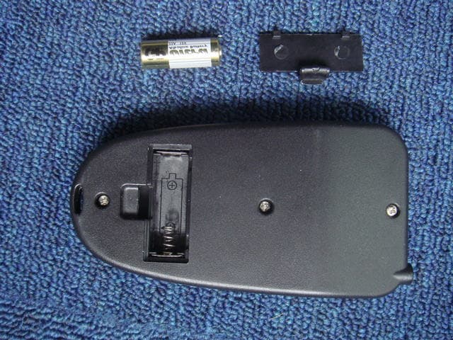
Click to zoom
Application Details
- Equipment Class
- DSC - Part 15 Security/Remote Control Transmitter
- Date of Grant
- Apr 30, 2007
- Application Purpose
- Original Equipment
- Date of Application
- Apr 29, 2007
- Equipment Note
- Controller and Transmitter
- Frequency Range
- 433.93000000 - 433.93000000
- Country
- China
Documents & Files
Document Text
Text extracted from the exhibit documents filed with the FCC. Open a document above to read the original.
Users Manual
Page 1-13 OPERATION MANUAL CONTROL Roll the knurled knob of the combined ON/OFF switch and Speed control forwards to turn on the power to the cart. Turning this knob further will progressively apply more power to the drive wheels and start the forward motion of the cart. Reversing this knob will reduce the speed of the cart. When this switch is turned ON for the first time the small LED on the handle should briefly illuminate to indicate that all electrical systems are operating properly. REMOTE CONTROL There is a cluster of 5 buttons in the middle of the remote control transmitter. The left direction arrow turns the cart to the left The right direction arrow turns the cart to the right Page 2-13 The “Up” direction button makes the cart go in a forward direction. It also provides acceleration. The “Down” direction button makes the cart go in the reverse direction. It is necessary to bring the trolley to a complete standstill before changing directions – forward to reverse – or reverse to forward. This button is also used for braking. The STOP button is used to stop the cart The two top buttons marked with SET and SAVE are only to be used if necessary for calibration of the alignment of the cart. See below ALIGNMENT ADJUSTMENT The two buttons at the top of the transmitter are only for emergency use if it is decided that the alignment of the cart is permanently and drastically pulling to one side or the other on flat ground. Before making any adjustments with these buttons it should be understood that a golf trolley with a very narrow wheelbase and with an uneven – and sometimes shifting – load will probably never be able to maintain a forward direction and a straight line – mainly because even a small directional bias at the start quickly magnifies to a much larger directional deviation. Indeed the whole point of having a remote operation cart is to be able to ignore the exact position of the cart – as long as it is within the fairway and clear of other golfers and water hazards. The user has the ability to bring his cart and clubs over to him when he gets up to his ball. To initiate this process start with a forward motion of the golf trolley, and then press the set button once. . ̧ Pressing the left arrow button one time will cause the left-hand drive wheel to reduce in speed by 1% ̧ Pressing the same button twice will produce a speed reduction of 2% ̧ This process can be repeated up to a differential reduction of 20% ̧ All of the above applies equally to the right arrow button ̧ Having completed this process pressing the save button will save the chosen settings ̧ If pressing the set button. then pressing save button. haven’t pressing left arrow or right arrow .The two drive wheel speed will the same. Page 3-13 TRANSMITTER USE • Your LX400 transmitter has been designed for ease of use whether you are left or right handed. • Take time to practice the difference between a single touch of a key and a prolonged push especially with left and right functions. • Never store the transmitter in a pocket with metal or sharp objects, or loose change. Never allow the transmitter to get immersed in water. • Because of the need for a removable battery cover, the transmitter is not waterproof, so when playing in the rain it is important to store it in a dry place like a pocket, and to protect it during use. • The transmitter takes a replaceable battery, you will need to carefully remove the belt-clip and then slide off the battery compartment cover to replace it. • Do not use a rechargeable battery in the handset as these batteries do not give sufficient voltage for this transmitter NOTE: This equipment has been tested and found to comply with the limits, pursuant to part 15 of the FCC Rules. These limits are designed to provide reasonable protection against harmful interference in a residential installation. This equipment generates uses and can radiate radio frequency energy and, if not installed and used in accordance with the instructions, or modified not expressed approved by the party responsible for compliance, may cause harmful interference to radiocommunications.
Test Report
Report No. FCC07-8018 Page 1 of 19 FCC TEST REPORT of Controller and Transimtter FCC ID UZ9HMM433MHZ Brand Name N/A Model No. HMM-SH Report No. FCC07-8018 Date Apr 24, 2007 Prepared for HONEST MECHANICAL MANUFACTURING CO.,LTD. Ting Cun,Duohu Street,Dongmei Industrial Park,Jindong District,Jinhua City,Zhejiang Prov Prepared by ShenZhen Electronic Product Quality Testing Center Electronic Testing Building, Shahe Road, Xili, Nanshan District, ShenZhen, 518055, P.R.China Tel: 86 755 26627338 Fax: 86 755 26627238 This test report consists of 19 pages in total. It may be duplicated completely for legal use with the approval of the applicant. It should not be reproduced except in full, without the written approval of our laboratory. The client should not use it to claim product endorsement by SET. The test results in the report only apply to the tested sample. The test report shall be invalid without all the signatures of testing engineers, reviewer and approver. Report No. FCC07-8018 Page 2 of 19 Table of Contents 1 Test Report Certification ............................................................................................................... 3 2 General Information ...................................................................................................................... 4 2.1 Description of EUT ............................................................................................................... 4 2.2 Objective ............................................................................................................................... 4 2.3 Test Standards and Results .................................................................................................... 4 2.4 List of Equipments Used ....................................................................................................... 5 2.5 Test Facility ........................................................................................................................... 5 2.6 Environmental conditions ..................................................................................................... 5 3 Radiated Emission Test ................................................................................................................. 6 3.1 Limits of Radiated Emission ................................................................................................. 6 3.2 Test Procedure ....................................................................................................................... 7 3.3 Test Setup .............................................................................................................................. 7 3.4 EUT Setup and Operating Conditions................................................................................... 8 3.5 Test Results............................................................................................................................ 8 4 Occupied Bandwidth Test ........................................................................................................... 12 4.1 Limits of Occupied Bandwidth ........................................................................................... 12 4.2 Test Procedure ..................................................................................................................... 12 4.3 Test Setup ............................................................................................................................ 12 4.4 EUT Setup and Operating Conditions................................................................................. 12 4.5 Test Results.......................................................................................................................... 12 5 Dwell Time Test ........................................................................................................................ 14 5.1 Limits of dwell time ............................................................................................................ 14 5.2 Test Procedure ..................................................................................................................... 14 5.3 Test Setup ............................................................................................................................ 14 5.4 EUT Setup and Operating Conditions................................................................................. 14 5.5 Test Results.......................................................................................................................... 14 Appendix IPhotographs of the EUT.............................................................................................. 16 Appendix IIPhotographs of the Test Configuration ...................................................................... 19 Report No. FCC07-8018 Page 4 of 19 2 General Information 2.1 Description of EUT Description: Controller and Transimtter Model No.: HMM-SH Type of Antenna: Integral Antenna Operation Frequency: 433.93MHz Power Supply: DC 12.0V(“AA” size 1.5V battery) Ports: NONE 1. Refer to technical document for further information. 2.2 Objective Perform EMC test according to FCC rules Part 2, Part 15 for FCC ID Certification. 2.3 Test Standards and Results The EUT has been tested according to 47 CFR − Part 2 Frequency Allocations and Radio Treaty Matters: General Rules and Regulations (10-1-05 Edition) − Part 15 Radio Frequency Devices (2006-08-14 Edition) Test items and the results are as bellow: ? FCC Rules Test Type Result Test Date 1 §15.231(a) Transmit time PASS 2007.03.06 2 §15.231(b) Radiated Emission PASS 2007.04.29 3 §15.231(c) Measured bandwidth PASS 2007.04.23 Report No. FCC07-8018 Page 5 of 19 2.4 List of Equipments Used Description Manufacturer Model No. Cal. Due Date Serial No. Test Receiver Rohde & Schwarz ESIB26 2007.06.05 A0304218 Loop Antenna Rohde & Schwarz HFH2-Z2 2007.06.05 A0304220 Ultra Broadband Ant. Rohde & Schwarz HL562…
Text truncated - open the document above for the full version.
Test Setup Photos
Test Photos 1. Radiated Emission Test (30MHz~1000MHz) 2. Radiated Emission Test (above 1000MHz)
Contact Information
Applicant
Echo Wang(Manager)
Technical Contact
Honest Mechanical Manufacturing Co LtdZhou Chi Hua
[email protected]86 0579 2160155
Ting Cun, Duohu Street, Dongmei Industrial Park · Jinhua · China
Non-Technical Contact
Honest Mechanical Manufacturing Co Ltd
86 0579 2160155
Test Firm
ShenZhen Electronic Product Quality Testing CenterXingsun Lin
Technical Specifications
| # | Rule Parts | Frequency Range | Power Output |
|---|---|---|---|
| 1 | 15.231 | 433.93 MHz - 433.93 MHz | - |