V2W3644Emergency Alrt System Encoder/Decoder
Sage Alerting Systems, Inc.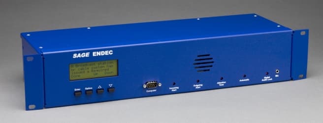
Click to zoom
Application Details
- Equipment Class
- EAD - Part 11 Emergency Alert Devices
- Date of Grant
- Apr 10, 2008
- Application Purpose
- Original Equipment
- Date of Application
- Apr 10, 2008
- Equipment Note
- Emergency Alrt System Encoder/Decoder
- Company
- Sage Alerting Systems, Inc.
- Country
- United States
Documents & Files
Document Text
Text extracted from the exhibit documents filed with the FCC. Open a document above to read the original.
Users Manual
Technical Support: 914-872-4069 Sage Alerting Systems, Inc. For update information & downloadable files: www.sagealertingsystems.com/support Model 3644 E mergency A lert S ystem Encoder/Decoder User‟s Guide and Reference Manual Version 1.0 For use with software version 1.0 SAGE DIGITAL ENDEC Copyright 2008, Sage Alerting Systems, Inc. All Rights Reserved. MHz Sub-Alert is a trademark of Mega Hertz VDS840EAS is a trademark of Video Data Systems, Inc. Chyron Codi is a trademark of Chyron Corporation All other Trademarks are hereby acknowledged. FCC Information: FCC ID V2W3644 The Sage Digital ENDEC is fully compliant with FCC Part 11. This device complies with Part 15 of the FCC Rules. Operation is subject to the following two conditions: (1) This device may not cause harmful interference, and (2) This device must accept any interference received, including interference that may cause undesired operation. Note: This equipment has been tested and found to comply with the limits for a Class A digital device, pursuant to part 15 of the FCC Rules. These limits are designed to provide reasonable protection against harmful interference when the equipment is operated in a commercial environment. This equipment generates, uses, and can radiate radio frequency energy and, if not installed and used in accordance with the instruction manual, may cause harmful interference to radio communications. Operation of this equipment in a residential area is likely to cause harmful interference in which case the user will be required to correct the interference at his own expense. Sage EAS ENDEC - Contents 3 Digital ENDEC Manual Rev 1.0 1. Quick Start 7 1.1 What you need to know about EAS 7 1.2 Bench Testing 8 1.3 Hookup 8 1.4 Customizing 9 1.4.1 Menu Basics 9 1.4.2 Passwords 11 1.4.3 Menu Annotation Format 11 1.4.4 Doing the Minimum 11 1.4.5 Sending a Weekly Test 12 1.4.6 Relaying a Monthly Test 12 1.4.7 Sample Instruction Sheet 12 2. Introduction to EAS 15 2.1 The National View 15 2.2 Your Local Area 15 2.3 Your responsibilities 16 2.4 The EAS Alert Format 16 3. Introduction to the ENDEC 19 3.1 Front Panel 19 3.2 ENDEC Back Panel 20 3.3 Memory - What’s Saved and What Isn’t 21 4. ENDEC Hardware Setup 23 4.1 Printer 23 4.2 Analog Audio 23 4.3 Audio Levels 25 4.4 Digital Audio 27 4.5 Digital Audio Levels 28 4.6 Serial Ports 28 4.7 Relays 29 5. ENDEC Software Setup 31 5.1 Call Sign 31 5.2 Time 32 5.3 Local Area 33 5.4 Filtering Incoming Alerts 34 5.5 Outgoing Alerts 38 5.6 Audio Sources 40 5.7 Relay Programming 40 5.7.1 Relay Program Definitions 41 5.7.2 Assigning Relay Programs 43 5.8 Random Required Weekly Test feature 44 5.9 Marine Location Codes 45 5.10 ENDECSET program 46 6. Typical Tasks 49 6.1 Weekly Test 49 6.2 Relaying an ALERT 49 6.3 Originating an Alert 50 6.3.1 Originating with templates 50 6.4 Viewing, Reprinting, Sending Old Alerts 51 6.5 Killing a Pending Alert 52 6.6 Playing Incoming Alert audio as it is Received 52 7. ENDEC Peripherals 53 7.1 Hand Control (RC-1) 53 Sage EAS ENDEC - Contents 4 Digital ENDEC Manual Rev 1.0 7.1.1 RS-232 Hookup 53 7.1.2 ENDEC Setup 53 7.1.3 Changing the RC-1 Default Parameters 54 7.1.4 Modifying model RC-1 for use with +5v ENDECs. 54 7.1.5 Using the Hand Control for Menus 55 7.1.6 Using the Hand Control One-touch buttons 55 7.1.7 Using the Macro Buttons 56 7.2 LED Sign 56 7.3 VDS Character Generator 56 7.4 Chyron CODI Character Generator 57 7.5 Monitor Radio Receivers 57 7.6 Modem Access 57 8. Interfacing with other Devices 59 8.1 Raw EAS input and output 59 8.2 Serial Printer 59 8.3 Alert Text Output (Generic Character Generator) 60 8.4 News Room Software 60 8.5 Commercial Tally 61 8.6 Daylight Only Stations 61 8.7 Older EBS Equipment 61 9. Controlling Multiple Stations 63 9.1 Station Numbers and Names 63 9.2 Configuring the ENDEC for MSRP Use 64 9.3 Controlling an Individual Station 65 9.4 Controlling Other Stations 65 9.5 MSRP Automatic Operation 65 9.6 Unattended Operation 66 10. Cable TV Options 67 10.1 Non-Volatile Audio Storage 67 10.2 MHz Sub Alert 67 10.2.1 MENU.MHZ SUB-ALERT.ATTN DURATION 68 10.2.2 MENU.MHZ SUB-ALERT.MHZ ENABLE 68 10.2.3 MENU.MHZ SUB-ALERT.REPEATS 68 10.3 MENU.MHZ SUB-ALERT.RWT MODE 68 10.3.1 MENU.MHZ SUB-ALERT.TUNE TO CHAN 68 10.3.2 MENU.MHZ SUB-ALERT.TUNE TO REP 69 10.3.3 MENU.MHZ SUB-ALERT.USER PAGE 69 11. ENDEC Command Reference 71 11.1 MENU.ALERTS.CLEAR ALERT LOG 71 11.2 MENU.ALERTS.CLEAR LED SIGN 71 11.3 MENU.ALERTS.ORIGINATE ALERT 71 11.4 MENU.ALERTS.PREVIEW AUDIO 71 11.5 MENU.ALERTS.PREVIEW NVAUDIO 71 11.6 MENU.ALERTS.RECORD AUDIO 71 11.7 MENU.ALERTS.RECORD NVAUDIO 72 11.8 MENU.ALERTS.SEND PENDING 73 11.9 MENU.ALERTS.VIEW ALERT LOG 74 11.10 MENU.CHANGE ADMIN 75 11.11 MENU.CHANGE PASSWORD 75 11.12 MENU.CHANGE PRO PASS 75 11.13 MENU.CONFIG.ALLOW BUILD EAN 76 11.14 MENU.CONFIG.ATTN DURATION 76 11.15 MENU.CONFIG.AUTO START 76 11.16 MENU.CONFIG.AUTO STOP. 76 Sage EAS ENDEC - Contents 5 Digital ENDEC Manual Rev 1.0 11.17 MENU.CONFIG.CALL SIGN 76 11.18 MENU.CONFIG.CODI CRAWL SPEED 76 11.19 MENU.CONFIG.CODI MODE 76 11.20 MENU.CONFIG.CRAWL REPS 76 11.21 MENU.CONFIG.CRAWL RWT 77 11.22 MENU.CONFIG.DEFAULT DURATION 77 11.23 MENU.CONFIG.DEFAULT REC 77 11.24 MENU.CONFIG.LANGUAGE 77 11.25 MENU.CONFIG.LED SIGN MODE 77 11.26 MENU.CONFIG.LED SIGN SOUND 77 11.27 MENU.CONFIG.LED SIGN TIME 77 11.28 MENU.CONFIG.MENU TIMEOUT 78 11.29 MENU.CONFIG.MODE 78 11.30 MENU.CONFIG.NV AUDIO LEN 78 11.31 MENU.CONFIG.NV LEAD-IN 78 11.32 MENU.CONFIG.NWS HUNT TIME 78 11.33 MENU.CONFIG.NWS PRACTICE 79 11.34 MENU.CONFIG.NWS SELECT 79 11.35 MENU.CONFIG.OLD SCAN METHOD 79 11.36 MENU.CONFIG.ORIGINATOR 79 11.37 MENU.CONFIG.PRINT ALL ALERTS 79 11.38 MENU.CONFIG.PRINT ZCZC 79 11.39 MENU.CONFIG.PRINTER 79 11.40 MENU.CONFIG.PRO EXTRA STAT 79 11.41 MENU.CONFIG.PRO READ ONLY 80 11.42 MENU.CONFIG.PROCESSOR LEAD 80 11.43 MENU.CONFIG.SCAN SELECT 80 11.44 MENU.CONFIG.STRICT TIME 80 11.45 MENU.CONFIG.UNKNOWN FIPS 80 11.46 MENU.CONFIG.VDS RELAY ON 80 11.47 MENU.DATE/TIME 81 11.48 MENU.D…
Text truncated - open the document above for the full version.
Block Diagram
Block Diagram FCC ID: V2W3644 This diagram shows the frequencies of all clocks in the device, and all inputs and outputs to the device. 24.576 MHz Sage Digital EndecBlock Diagram (Overview) Two Serial PortsTwo USB Ports10/100 LAN Port Microprocessor Board Power 19 VDC +12, +9, +5, +3.3,+2.5, +1.8, +1.5,-5, -12 volts 14.74 MHz25.00 MHz FPGA 4 x 20 LCD 22.5792 MHz ADC CODECS (3) AES Audio UARTS (4) 3.072 MHz6.144 MHz 22.5792 or 24.576 MHz 768 kHz DSP 40.00 MHz Four Serial Ports AES/EBU digitalaudio Encoder audio In 6 monitor audioports in Speaker/Line Out Five Status LEDs Four UI Buttons Four Status Relays Four Contact Closure Inputs Program Audio Out Microphone In
External Photos
Sage Alerting Systems, Inc. Page 1 of 3 Exterior Photographs Exterior Photographs FCC ID: V2W3644 Exterior. Note – In the final enclosure “SAGE ENDEC” is replaced by “SAGE DIGITAL ENDEC”. Sage Alerting Systems, Inc. Page 2 of 3 Exterior Photographs Exterior Front. Note – In the final enclosure “SAGE ENDEC” is replaced by “SAGE DIGITAL ENDEC”. Sage Alerting Systems, Inc. Page 3 of 3 Exterior Photographs Exterior Back. Note: In the final product, “15 VAC” is replaced with “19 VDC”.
ID Label/Location Info
Label Placement FCC ID: V2W3644 1. Label Content 2. Placement Sage Digital ENDEC FCC ID V2W3644 www.sagealertingsystems.com This device complies with parts 11 and 15 of the FCC Rules. Operation is sub ject to the following two conditions: (1) This device ma y not cause harmful interference, and (2) This device must accept an y interference received, including interference that may cause undesired operation. LAN 10/100 Com 5 Com 6 Com 3 Com 4 Attn RlyAttn RlyEnc RlyEnc RlyDec RlyDec RlyGndMon 1 inMon 2 inMon 3 inMon 4 inMon 5 inMon 6 inGndGndEnc inD in 1Line OutSpkr OutSpkr In . Gnd USB 1 USB 2 Com 2 Digital Audio InOut Main Audio InMain/Alert Audio Out LR LR Rly 4Rly 4D in 2D in 3D in 4D in 5 On/Off PWR FCC ID LABEL 2.50in. 1.00in. Material:Permanent Polyester Adhesive:Acrylic Brady LAT-21-747-1 or equivalent Rear Panel
Internal Photos
Sage Alerting Systems, Inc. Page 1 of 8 Board Photographs Interior Photographs FCC ID: V2W3644 Top cover removed. Sage Alerting Systems, Inc. Page 2 of 8 Board Photographs Front Panel – reverse Sage Alerting Systems, Inc. Page 3 of 8 Board Photographs Main PCB - Top Sage Alerting Systems, Inc. Page 4 of 8 Board Photographs Main PCB - Bottom Sage Alerting Systems, Inc. Page 5 of 8 Board Photographs CPU - Top Sage Alerting Systems, Inc. Page 6 of 8 Board Photographs CPU - Bottom Sage Alerting Systems, Inc. Page 7 of 8 Board Photographs Audio Interface - Top Sage Alerting Systems, Inc. Page 8 of 8 Board Photographs Audio Interface - Bottom
Operational Description
Brief Functional Description Page 1 of 2. Sage Digital ENDEC Brief Functional Description FCC ID: V2W3644 Theory of Operation The Sage Digital ENDEC monitors audio on six unbalanced input ports, looking for EAS data tones or the two-tone attention signal. When the EAS data tones are received, the ENDEC checks for proper syntax, then a match of at least two headers, then checks against the most recent 10 alerts sent or received for duplicates. Finally, it checks against user settable “filters” that control what is done with the incoming alert. Actions include log only, hold then delete, hold then relay, and immediate relay. The ENDEC will record up to two minutes of audio for each active alert in its internal FLASH memory. The user can assign a priority to each filter, high priority alerts replace lower priority alerts in FLASH audio memory. The EAN message always has the highest priority, and the audio storage is used as a two minute ring buffer so that the length of an EAN message is unlimited. Internally, the ENDEC can store much more than two minutes, but to simplify operations for typical users, the ENDEC makes only the most recently received alert by priority available for relay. When receiving an alert, the ENDEC restarts its internal audio recorder at the end of the two tone alert signal or at the end of the NWS 1050 Hz attention signal so that these signals are not included as part of the two minute limit, and then are not rebroadcast when the alert is relayed. An alert can also be originated from the front panel, or with optional hardware or software remote controls. In the case of the required weekly test, only the headers and end of message data is required. For alerts that do require audio, it can be supplied via the “encoder in” connector on the back of the ENDEC, or the microphone input connector on the front of the ENDEC. Major Block Descriptions Refer to the “Block Diagram” exhibit. Power supply. The input voltage of 19v is supplied from an external switching power supply. Microprocessor Board. All of the user interface functions and overall control of the ENDEC are performed by this board. It has a direct connection to USB, LAN, and two serial ports, as well as the 4x20 character LCD display. Regulated +5v is supplied to this board. FPGA. This chip provides the glue logic between the CPU, DSP, ADC, and the codecs. DSP. This chip receives digitized data from the codecs, making the digital audio available to the CPU for storage. It also detects the EAS data tones. It detects the EAS two tone and the NWS 1050 Hz tone. It generates all tones needed for transmission of data, and interfaces to the codecs to provide conversion of stored digital audio to analog when sending an alert. CODECs. These three chips provide six channels of audio input and two channels of audio output, under direction of the DSP. One output channel drives the speaker/line out for local monitoring, the other output channel is switched into the program stream for alerts. Brief Functional Description Page 2 of 2. Sage Digital ENDEC AES audio. This set of two chips allows the ENDEC to pass through digital audio and to switch in alert audio. ADC. This chip digitizes the encoder in and the microphone in audio when sending a locally generated alert. UARTs. An additional four uarts are provided on the main PCB for a total of six.
Schematics
Schematics are not required for unintentional radiators.
Test Report
Report Number 3148183BOX-001 Page 1 of 59 EMISSIONS TEST REPORT Report Number: 3148183BOX-001 Project Number: 3148183 Testing performed on the Endec Model: 3644 FCC ID: V2W3644 To CFR47 Telecommunications Part 11 “Emergency Alert System (EAS)” Subpart B Part 15 Subpart B “Unintentional Radiators” For Sage Alerting Systems Inc. Test Performed by: Test Authorized by: Intertek – ETL SEMKO 70 Codman Hill Road Boxborough, MA 01719 Sage Alerting Systems Inc. 800 Westchester Avenue Suite 641 North Rye Brook, NY 10573 Prepared by: Date: 04/09/2008 Nicholas Abbondante Reviewed by: Date: 04/10/08 Jeff Goulet This report is for the exclusive use of Intertek’s Client and is provided pursuant to the agreement between Intertek and its Client. Intertek’s responsibility and liability are limited to the terms and conditions of the agreement. Intertek assumes no liability to any party, other than to the Client in accordance with the agreement, for any loss, expense or damage occasioned by the use of this report. Only the Client is authorized to copy or distribute this report and then only in its entirety. Any use of the Intertek name or one of its marks for the sale or advertisement of the tested material, product or service must first be approved in writing by Intertek. The observations and test results in this report are relevant only to the sample tested. This report by itself does not imply that the material, product, or service is or has ever been under an Intertek certification program. This report must not be used to claim product endorsement by A2LA, NIST nor any other agency of the U.S. Government. Report Number 3148183BOX-001 Page 2 of 59 1.0 Job Description 1.1 Client Information This EUT has been tested at the request of: Company: Sage Alerting Systems Inc. 800 Westchester Avenue Suite 641 North Rye Brook, NY 10573 Contact: Mr. Harold Price Telephone: Fax: Email: 412-835-2994 412-833-9482 [email protected] 1.2 Equipment Under Test Equipment Type: Endec Model Number(s): 3644 Serial number(s): 1, 2 EUT receive date: 04/02/2008 EUT received condition: Prototypes in Good Condition Test start date: 04/02/2008 Test end date: 04/09/2008 1.3 Test Plan Reference: Tested according to the standards listed and ANSI C63.4:2003 1.4 Test Configuration 1.4.1 Block Diagram Part 11 Testing: Part 15 Testing: Endec Support Encoder/Decoder Laptop RS-232 3x Wire Power Power Remote Endec Power Ethernet RS-232 USB 3x Audio Wire, 600 Ohm Termination Ground, Monitor 1, Monitor 2 RS-232 Ground Freeplay Radio Headphone out into Mic in Report Number 3148183BOX-001 Page 3 of 59 1.4.2. Cables: Cable Shielding Connector Length (m) Qty. Ground None Wire 1.0 1 Audio, Ground Braid Wire/Drain Wire, 600 Ohm Term. 1.2 1 Audio, Monitor 1 Braid Wire/Drain Wire, 600 Ohm Term. 1.2 1 Audio, Monitor 2 Braid Wire/Drain Wire, 600 Ohm Term. 1.2 1 XLR Cable, Main/Alert Out Braid Metal/360 Balanced XLR 1.85 1 USB Braid Metal/360 USB 3.0 1 Ethernet None Plastic RJ-45 2.9 1 RS-232, COM1 Braid Metal/360 DB9 1.8 1 RS-232, COM2 Braid Metal/360 DB9 2.9 1 AC Mains None Plastic 1.8 1 DC Mains None Metal/Jack 1.8 1 Cable description pertains to Part 15 testing 1.4.3. Support Equipment: Name: Model No.: Serial No.: Sage Endec 1822 D6602 Name: Model No.: Serial No.: Sage Endec Remote RC-1 6279783 Name: Model No.: Serial No.: CUI Inc. AC/DC Power Supply 3A-621DN19 N/L Name: Model No.: Serial No.: Radio Freeplay SFD 00 034 590 Name: Model No.: Serial No.: Laptop N/A N/A 1.5 Mode(s) of Operation: The EUT was being fed 19V DC by the EUT AC/DC power supply, which was powered from 120V/60Hz AC power, except during the voltage variation test. 1.6 Modifications required for compliance: A Wurth Elektronik ferrite #74271131 was placed in a single pass configuration located at the EUT, on both the front panel RS-232 cable and on the rear panel USB cable. The EUT was grounded during testing from the ground lug to the ground plane. Report Number 3148183BOX-001 Page 4 of 59 2.0 Test Summary TEST STANDARD RESULTS FCC Part 11 Subpart B & FCC Part 15 Subpart B SUB-TEST TEST PARAMETER COMMENT EAS Protocol FCC 11.31 The EAS protocol must meet the protocol requirements of 11.31. See Test Details for a detailed list of requirements. Pass EAS Encoder FCC 11.32 The EAS encoder must meet the operational requirements of 11.32. See Test Details for a detailed list of requirements. Pass EAS Decoder FCC 11.33 The EAS decoder must meet the operational requirements of 11.33. See Test Details for a detailed list of requirements. Pass Radiated Emissions FCC 15.109 Emissions must be below the 15.109 Class A limits Pass AC Line-Conducted Emissions FCC 15.107 Emissions must be below the 15.107 Class A limits Pass REVISION SUMMARY – The following changes have been made to this Report: Date Project No. Project Handler Page(s) Item Description of Change Report Number 3148183BOX-001 Page 5 of 59 3.0 Sample Calculations The field strength is calculated by adding the Antenna Factor and Cable Factor, and subtracting the Amplifier Gain (if any) from the measured reading. The basic equation with a sample calculation is as follows: FS = RA + AF + CF - AG Where FS = Field Strength in dBμV/m RA = Receiver Amplitude (including preamplifier) in dBμV CF = Cable Attenuation Factor in dB AF = Antenna Factor in dB AG = Amplifier Gain in dB In the following table(s), the reading shown on the data table reflects the preamplifier gain. An example for the calculations in the following table is as follows. Assume a receiver reading of 52.0 dBμV is obtained. The antenna factor of 7.4 dB and cable factor of 1.6 dB is added. The amplifier gain of 29 dB is subtracted, giving a field strength of 32 dBμV/m. This value in dBμV/m was converted to its corresponding level in μV/m. RA = 52.0 dBμV AF = 7.4 dB/m CF = 1.6 dB AG = 29.0 dB FS = 32 dBμV/m Level in μV/m = [10( 32 dBμV/m)/20] = 39.8 μV/m The following is how net line-conducted readings were determined: NF = RF + LF + CF + AF Where NF = Net Reading …
Text truncated - open the document above for the full version.
Test Setup Photos
Report Number 3148183BOX-001 Page 36 of 59 Setup Photos General Tests Report Number 3148183BOX-001 Page 37 of 59 Setup Photos 11.32(d) AM Frequency Report Number 3148183BOX-001 Page 38 of 59 Setup Photos 11.32(d) FM Frequency Report Number 3148183BOX-001 Page 39 of 59 Setup Photos 11.32(b) Report Number 3148183BOX-001 Page 40 of 59 Setup Photos 11.32(b) Report Number 3148183BOX-001 Page 54 of 59 Radiated Emissions Setup Photos Report Number 3148183BOX-001 Page 55 of 59 Radiated Emissions Setup Photos Report Number 3148183BOX-001 Page 58 of 59 AC Line-Conducted Emissions Setup Photos Report Number 3148183BOX-001 Page 59 of 59 AC Line-Conducted Emissions Setup Photos
Contact Information
Applicant
Harold E Price(President)
Test Firm
Intertek Testing Services NA Inc.Yaqing Liu
[email protected]978 635 8662
Technical Specifications
| # | Rule Parts | Frequency Range | Power Output |
|---|---|---|---|
| 1 | 11 | - | - |