V5SEAPGTWY-0822EAPRO-GTWY
Winland Electronics, Inc.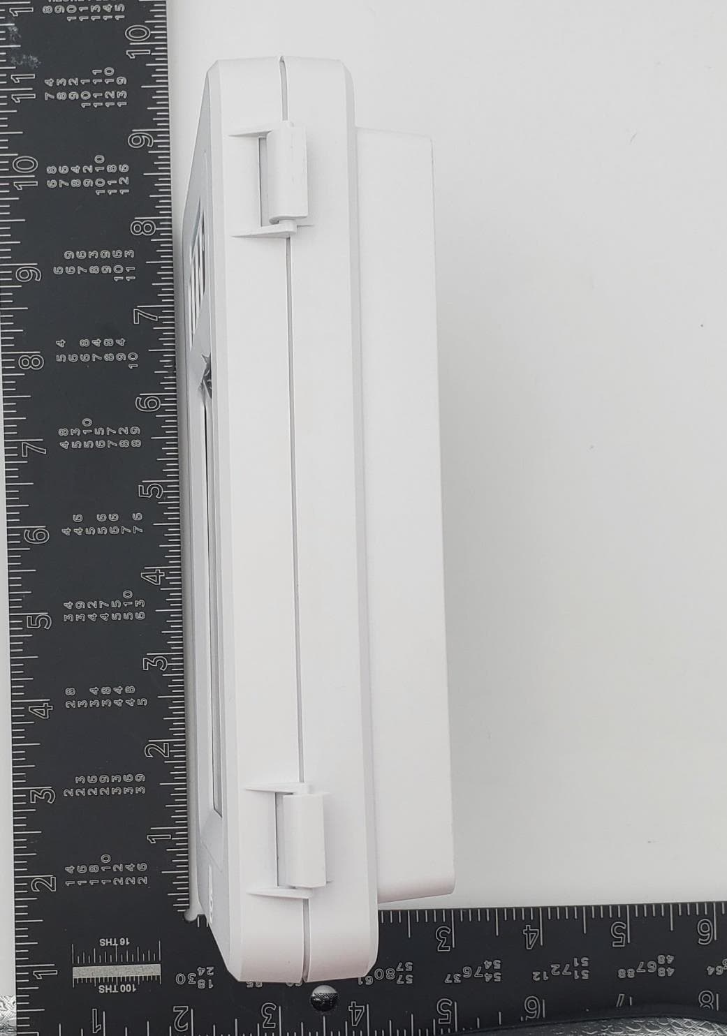
Click to zoom
Application Details
- Equipment Class
- DTS - Digital Transmission System
- Date of Grant
- Dec 29, 2022
- Application Purpose
- Original Equipment
- Date of Application
- Dec 29, 2022
- Equipment Note
- EAPRO-GTWY
- Frequency Range
- 2405.00000000 - 2479.00000000
- Company
- Winland Electronics, Inc.
- Country
- United States
Documents & Files
Document Text
Text extracted from the exhibit documents filed with the FCC. Open a document above to read the original.
Users Manual
Page ii Winland Electronics, Inc. Limitations of the Alarm System or Device. While your alarm system or device is reliable and sophisticated, it does not offer guaranteed protection against burglary, fire or other emergency. Any security product, whether commer- cial or residential, is subject to compromise or failure-to-warn for a variety of reasons. These include: • Individuals may gain access through unprotected openings or have the technical sophistication to bypass an alarm sensor or disconnect an alarm warning device. • Monitoring devices will not operate without power. Devices powered by AC will not work if their AC power supply is off for any reason. If system has battery backup, batteries that are not maintained can fail to provide the necessary power for devices to function prop- erly. • Alarm warning devices such as sirens, bells, and horns may not alert people or awaken sleepers if they are located on the other side of closed or partly closed doors. If warning devices are on a different level of the residence from the bedrooms, they are less likely to awaken or alert people inside the bedrooms. • Telephone lines needed to transmit alarm signals from a premises to a central monitoring station may be out of service, and are subject to compromise by sophisticated means of attack. • Signals sent by wireless transmitters may be blocked or reflected by metal before they reach the alarm receiver. Even if the signal path has been recently checked during a weekly test, blockage can occur if a metal object is moved into the path. • Even if the system responds to the emergency as intended and is a monitored alarm system, the authorities may not respond appropriately. • This equipment, like other electrical devices, is subject to component failure. • The most common cause of an alarm system not functioning properly is due to inadequate maintenance. Your alarm system should be tested weekly to make sure all de- tection devices are operating properly. Your control panel and keypads should be tested as well. Installing an alarm system may make you eligible for lower insurance rates, but an alarm system is not a substitute for insurance. Homeowners, property owners, and renters should continue to insure their lives and property. Page iii Record of Revisions REV NO.DATEDESCRIPTION OriginalMay 2022Initial Issue Notice This document will refer to INSIGHT throughout. INSIGHT is a cloud based platform for remote viewing and management of the EA800-ip device and the EAPro ® . INSIGHT is sold separately and not required to use the EAPro ® Gateway. The EAPro ® can be used in standalone mode, or along with INSIGHT in a connected mode. The EAPro ® -Gateway monitors the environmental conditions detected by connected sensors and provides alarm signals when monitored conditions at any sensor exceeds the user-programmable set points. Winland INSIGHT provides complete realtime cloudbased visibility of data from EAPro ® -Gateway monitored critical condition environments. The systems detailed and customized response protocols, data logs, and extreme flexibility, provide the fastest resolution of incidents by making the notification immediately actionable. NOTE: As of Firmware 22.11.11, the EAPro-Gateway sends notifications to INSIGHT, however INSIGHT does not send out notifications to text/emails as this time. Page iv Winland Electronics, Inc. Page Left Blank Page v TABLE OF CONTENTS Foreword 1 Safety Information 1 General Information 3 Overview 3 How to Use This Manual 4 Symbols On the Product or Manual Labeling 5 Relay Block Diagram 5 EAPro ® ‑Gateway 6 Home Screen 8 Access Control 11 Connections 12 Configuration Parameters 13 Sensors 14 Sensor Programming and Parameter Descriptions 18 Relay Operation 21 Data Logs 21 Installation 22 Installation Tools and Supplies 22 Power Requirements 22 Mount the Rear Plate 23 Connecting Power 23 Initial Start‑Up Procedure 24 Install Wired Sensors 24 Connect Wired Sensors 24 Install Wireless Sensor 25 Program 27 Main Menu 27 Configure System 27 Add Sensor 28 Add User 29 Set System Time and Date Format 29 Set Date and Time 29 Set Lock Mode 30 Select RF Channel 30 Configure Relays 30 Configure Relay State 30 Set Buzzer Triggers 31 Set Light Triggers 31 Operation 32 Acknowledge Alarm 32 Clear Alarm 32 View Sensor Details 32 View Notification Log 32 View Event Log 32 View Sensor Logs 33 View User Logs 33 View About 33 Page vi Winland Electronics, Inc. Clear Notification Logs 33 Clear Sensor Logs 33 Export Logs 34 Data Logs 34 Maintenance 35 Edit Sensor 35 Replace Wireless Transmitter 38 Delete Sensor 38 Pause Sensor 39 Test Sensor 39 Edit User 39 Delete User 40 Configure User Mode 40 Sync Users 40 Save System Configuration 40 Edit Network Wi‑Fi 41 Edit Ethernet Settings 41 Update Firmware 42 Reset to Factory Defaults 43 Reboot System 43 Troubleshooting 44 Winland Technical Support 44 Specifications 45 Warranty and Service Information 46 Page vii LIST OF FIGURES Figure 1: EAPro ® ‑Gateway 3 Figure 2: EAPro ® ‑Gateway Block Diagram 6 Figure 3: EAPro ® ‑Gateway Front 6 Figure 4: Home Screen Sensor Tile 9 Figure 5: Home Screen Tile Examples 9 Figure 6: Connections 13 Figure 7: Wiring Diagram for 4–20mA Sensor – Aux Power Supply 17 Figure 8: Wiring Diagram for 4–20mA Sensor – External Power Supply 17 Figure 9: Wired Sensor Connection: Temperature Probe, WaterBug®, and Dry Contact 25 Figure 10: Wired Sensor Connection: HA‑III+ 25 Figure 11: Wired Sensor Connection: 4–20mA 25 Figure 12: Wireless Sensor MAC Address and ID Location 26 Figure 13: Main Menu 27 Page viii Winland Electronics, Inc. Page Left Blank Page ix LIST OF TABLES Table 1: Symbols on Product or Manual Labeling 5 Table 2: EAPro ® ‑Gateway Parts: Description 7 Table 3: Icons on Touchscreen 7 Table 4: Home Screen Display 8 Table 5: Home Screen Sensor Tile 9 Table 6: Example of Sensor Status on Home Screen Tiles 9 Table 7: User Access Levels 11 Table 8: Lock Setting 12 Table 9: Connector Functions 13 Table 10: Configura…
Text truncated - open the document above for the full version.
Cover Letter(s)
424 North Riverfront Drive, Suite 200 • Mankato, MN 56001 • 1-800-635-4269 • www.winland.com October 17, 2022 Federal Communications Commission Subject: Cover Letter for FCC application for Certification of FCC ID: V5SEAPGTWY-0822 TO WHOM IT MAY CONCERN: The model EAPRO-GTWY is a console device that communicates with various accessories used for environmental monitoring. One of the accessories are remote sensors that communicate wirelessly via LoRa over the frequency bands 2405MHz to 2479MHz. This device allows for connection to a cloud back-end for remote data monitoring and configuration via ethernet or WiFi. There is a touch screen LCD that allows for local configuration and monitoring as well. NextGen RF Design, Inc. is an engineering services company contracted by Winland Electronics to design and manufacture the EAPro product family, which is inclusive of the gateway and wireless sensors. This also includes facilitating the regulatory testing, documentation, review and approval of test reports, etc. This application is to seek original certification, as compliant with FCC CFR47 Rule Parts 15.247. Sincerely, Kory Meyers NextGen RF Design Inc. Sr. Project Engineer
Cover Letter(s)
424 North Riverfront Drive, Suite 200 • Mankato, MN 56001 • 1-800-635-4269 • www.winland.com November 12, 2022 Federal Communications Commission Authorization and Evaluation Division 7435 Oakland Mills Road Columbia, Maryland 21046 Re: Request for confidentiality FCC ID: V5SEAPGTWY-0822 We hereby respectfully request that under the provision of 47 CFR 0.459 and 0.457(d) the documents listed below and attached with this application for certification be provided with confidential status. • Altium_BOM-Gateway_Rev3.xlsx • Winland Gateway Frequency Block Diagram Rev 2.pdf • EAPro Operational Description (Gateway and Sensors) Rev A.docx • Schematic, Gateway, Rev 3.pdf Any exhibit / information for which we have requested confidentiality, but which may not be accorded such treatment by the FCC, should be returned to us. The documents listed above contain trade secrets that are treated as confidential by us. Substantial competitive harm to us could result should they be made available to the public Sincerely, Kory M. Meyers NextGen RF Design Inc. Senior Project Engineer
Cover Letter(s)
424 North Riverfront Drive, Suite 200 • Mankato, MN 56001 • 1‐800‐635‐4269 • www.winland.com August 22, 2022 To whom it may concern, We, the undersigned, hereby authorize Kory Meyers ([email protected]) of NextGen RF Design to act on our behalf, as our agent, in the following matters related to the FCC and/or Industry Canada approval of our products: report submittal, related correspondence, the signing of all documents relating to these matters, and any other lawful activity necessary to obtain such certification. Any act carried out by Kory Meyers of NextGen RF Design within the scope of this authorization shall have the same effect as our own. This authorization shall expire 12 months from original date. Sincerely, Mark Ubben Director of Technology Winland Electronics, Inc. [email protected]
External Photos
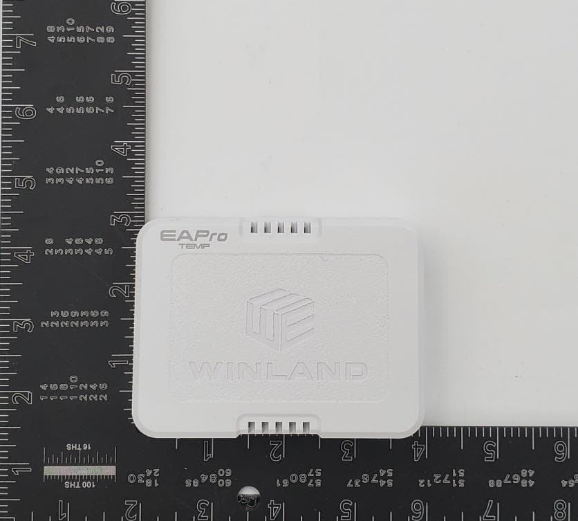
Winland EA Pro Gateway. Photos for Submittal (external) There are no accessories to be included. EA Pro Gateway Front EA Pro Gateway Back EA Pro Gateway Top EA Pro Gateway Right EA Pro Gateway Bottom EA Pro Gateway Left
ID Label/Location Info
Adhesive label applied directly to housing, label specs & location indicated as follows:
Internal Photos
Winland EA Pro Gateway. Photos for Submittal (internal) EA Pro Gateway PCB Top EA Pro Gateway PCB Bottom EA Pro Gateway PCB Top (Shield will normally be installed) EA Pro Gateway PCB Bottom
Operational Description
This report must not be used to claim product certification, approval, or endorsement by A2LA or any agency of the U.S. Government. This Report shall not be reproduced, except in full without written approval of the laboratory. NextGen RF Design Titan Gateway and Titan Sensor Report: NGRF0059.0, Issue Date: November 22, 2022 REVISION HISTORY 2018.07.17 Revision Number Description Date (yyyy-mm-dd) Page Number 00 None Report No. NGRF00592/30 ACCREDITATIONS AND AUTHORIZATIONS 2021.09.01 United States FCC - Designated by the FCC as a Telecommunications Certification Body (TCB). Certification chambers, Open Area Test Sites, and conducted measurement facilities are listed with the FCC. A2LA - Each laboratory is accredited by A2LA to ISO / IEC 17025, and as a product certifier to ISO / IEC 17065 which allows Element to certify transmitters to FCC and IC specifications. Canada ISED - Recognized by Innovation, Science and Economic Development Canada as a Certification Body (CB) and as a CAB for the acceptance of test data. European Union European Commission – Recognized as an EU Notified Body validated for the EMCD and RED Directives. United Kingdom BEIS – Recognized by the UK as an Approved Body under the UK Radio Equipment and UK EMC Regulations. Australia/New Zealand ACMA - Recognized by ACMA as a CAB for the acceptance of test data. Korea MSIT / RRA - Recognized by KCC’s RRA as a CAB for the acceptance of test data. Japan VCCI - Associate Member of the VCCI. Conducted and radiated measurement facilities are registered. Taiwan BSMI – Recognized by BSMI as a CAB for the acceptance of test data. NCC - Recognized by NCC as a CAB for the acceptance of test data. Singapore IDA – Recognized by IDA as a CAB for the acceptance of test data. Israel MOC – Recognized by MOC as a CAB for the acceptance of test data. Hong Kong OFCA – Recognized by OFCA as a CAB for the acceptance of test data. Vietnam MIC – Recognized by MIC as a CAB for the acceptance of test data. SCOPE For details on the Scopes of our Accreditations, please visit: California Minnesota Oregon Texas Washington Report No. NGRF00593/30 FACILITIES 2020.12.15 California Labs OC01-17 41 Tesla Irvine, CA 92618 (949) 861-8918 Minnesota Labs MN01-11 9349 W Broadway Ave. Brooklyn Park, MN 55445 (612)-638-5136 Oregon Labs EV01-12 6775 NE Evergreen Pkwy #400 Hillsboro, OR 97124 (503) 844-4066 Texas Labs TX01-09 3801 E Plano Pkwy Plano, TX 75074 (469) 304-5255 Washington Labs NC01-05 19201 120 th Ave NE Bothell, WA 98011 (425)984-6600 A2LA Lab Code: 3310.04 Lab Code: 3310.05 Lab Code: 3310.02 Lab Code: 3310.03 Lab Code: 3310.06 Innovation, Science and Economic Development Canada 2834B-1, 2834B-3 2834E-1, 2834E-3 2834D-1 2834G-1 2834F-1 BSMI SL2-IN-E-1154R SL2-IN-E-1152R SL2-IN-E-1017 SL2-IN-E-1158R SL2-IN-E-1153R VCCI A-0029 A-0109 A-0108 A-0201 A-0110 Recognized Phase I CAB for ISED, ACMA, BSMI, IDA, KCC/RRA, MIC, MOC, NCC, OFCA US0158 US0175 US0017 US0191 US0157 Report No. NGRF00594/30 PRODUCT DESCRIPTION 2018-07-17 Client and Equipment under Test (EUT) Information Company Name: NextGen RF Design Address: 2130 Howard Drive West City, State, Zip: North Mankato, MN 56003 Test Requested By: Ross Loven EUT: Titan Gateway and Titan Sensor First Date of Test: November 11, 2022 Last Date of Test: November 11, 2022 Receipt Date of Samples: November 11, 2022 Equipment Design Stage: Preproduction Equipment Condition: No Damage Purchase Authorization: Verified Information Provided by the Party Requesting the Test Functional Description of the EUT: Gateway system containing a 2.4 GHz LoRa and a pre-approved 802.11bgn 20 MHz SISO radio module. Sensors containing a 2.4 GHz LoRa radio. EAPRO-GTWY, ENVIROALERT Professional Gateway, EAPRO- WTS, ENVIROALERT Professional Wireless Temperature Sensor, EAPRO-WHS, ENVIROALERT Professional Wireless Humidity Sensor, EAPRO-WMFT, ENVIROALERT Professional Wireless Multi-Function Transmitter, EAPRO-WMFT-R, ENVIROALERT Professional Wireless Multi-Function Transmitter with Relay Testing Objective: To obtain 2D antenna pattern measurements and calculated antenna performance values. Report No. NGRF00595/30 CONFIGURATIONS 2018-07-17 Configuration NGRF0059- 1 EUT Description Manufacturer Model/Part Number Serial Number Wireless Sensor WINLAND Electronics, Inc Titan Sensor None Configuration NGRF0059- 2 EUT Description Manufacturer Model/Part Number Serial Number Wireless Gateway WINLAND Electronics, Inc Titan Gateway None Report No. NGRF00596/30 MODIFICATIONS 2018-07-17 Equipment Modifications Item Date Test Modification Note Disposition of EUT 1 2022-11-07 2D Polar Plots Tested as delivered to Test Station. No EMI suppression devices were added or modified during this test. Scheduled testing was completed. Report No. NGRF00597/30 2D POLAR PLOTS PSA-ESCI 2022.08.23.0 description PSA-ESCI 2022.08.23.0 MODES OF OPERATION CW - 2440 MHz CONFIGURATIONS INVESTIGATED NGRF0059 - 2 FREQUENCY RANGE INVESTIGATED Start Frequency2440 MHzStop Frequency2440 MHz SAMPLE CALCULATIONS Max Absolute Gain of AUT = G_ref - (E_ref - E_aut) + L_c Where: G_ref = gain of reference antenna (dBi)E_ref = electric field strength in dBuV/m E_aut = electric field strength in dBuV/mL_c = AUT setup loss TEST EQUIPMENT ID EVB AFI AIZ TFU REM AHC TEST DESCRIPTION Testing was performed using the mode(s) of operation and configuration(s) noted within the report. The individuals and/or the organization requesting the test provided the modes, configurations and settings used to complete the evaluation. The actual test parameters are specified in the test data, this includes items such as investigated frequency range (scanned) and test levels. The testing methods and performance specifications, as well as the test site used for the evaluation are indicated in the test data. The test data represents the configuration / operating mode/ model that produced the highest emission levels as compared to the specification limit. DescriptionManufacturerModelLast Cal.Cal. Due Antenna…
Text truncated - open the document above for the full version.
Operational Description
EAPro® Antenna Datasheet REV 3 - REVISED NOVEMBER 2022 1 FEATURES • Integrated PCB monopole antennas (Gateway & Sensor) • Frequency range 2405 MHz – 2492 MHz • Peak Gain (Gateway Antenna 1) = 2.21 dBi • Peak Gain (Gateway Antenna 2) = 1.80 dBi • Peak Gain (Sensor) = 3.16 dBi • No provisions for external antenna, can’t be modified by end-user • Gateway Antenna Dimensions (ANT1/ANT2): Area = 0.155” x 0.580”, total length = 1.06”, trace width = 20mils • Wireless Sensor Dimensions: length = 0.685”, trace width = 20mils • See Report-NGRF0059 for antenna pattern data GENERAL DESCRIPTION The EnviroAlert Professional® Gateway & Wireless sensors contain internal PCB trace antennas for the LoRa® 2.4GHz wireless interface. The antennas are fixed, located internal to the product, making them invisible to the end-user. The antenna structures are simple monopole PCB traces, located near the edges of the PCB. There are no provisions for the antennas to be modified, nor is there any hardware to support adding external antennas. The wireless sensor PCB design is the same board for all model types (EAPRO-WTS, EAPRO-WHS, EAPRO- WMFT, EAPRO-WMFT-R), which means no change in the antenna design across all models. EAPro® Antenna Datasheet REV 3 - REVISED NOVEMBER 2022 2 A N T 1 A N T 2 Figure 1: Gateway PCB Antenna Locations Figure 2: Gateway Antenna Dimensions EAPro® Antenna Datasheet REV 3 - REVISED NOVEMBER 2022 3 Figure 3: Wireless Sensor PCB Location Figure 4: Wireless Sensor Antenna Dimensions
RF Exposure Info
This report must not be used to claim product certification, approval, or endorsement by A2LA or any agency of the U.S. Government. This Report shall not be reproduced, except in full without written approval of the laboratory. NextGen RF Design Titan Gateway FCC 1.1307:2022 2.4 GHz DTS Radio Report: NGRF0028.7, Issue Date: December 22, 2022 CERTIFICATE OF EVALUATION 2018-09-14 Product compliance is the responsibility of the client; therefore, the tests and equipment modes of operation represented in this report were agreed upon by the client, prior to testing. The results of this test pertain only to the sample(s) tested. The specific description is noted in each of the individual sections of the test report supporting this certificate of test. This report reflects only those tests from the referenced standards shown in the certificate of test. It does not include inspection or verification of labels, identification, marking or user information. As indicated in the Statement of Work sent with the quotation, Element’s standard process is to always use the latest published version of the test methods even when earlier versions are cited in the test specification. Issuance of a purchase order was de facto acceptance of this approach. Otherwise, the client would have advised Element in writing of the specific version of the test methods they wanted applied to the subject testing Last Date of Evaluation: December 21, 2022 NextGen RF Design EUT: Titan Gateway RF Exposure Evaluation Standards Specification Method FCC 1.1307:2022 FCC 1.1307:2022 Results Method Clause Description Applied Results Comments (b)(3)(i)(B) Exemption From RF Exposure Evaluation Yes Pass N/A Deviations From Evaluation Standards None Approved By: Donald Facteau, Process Architect Report No. NGRF0028.72/11 ACCREDITATIONS AND AUTHORIZATIONS 2021.09.01 United States FCC - Designated by the FCC as a Telecommunications Certification Body (TCB). Certification chambers, Open Area Test Sites, and conducted measurement facilities are listed with the FCC. A2LA - Each laboratory is accredited by A2LA to ISO / IEC 17025, and as a product certifier to ISO / IEC 17065 which allows Element to certify transmitters to FCC and IC specifications. Canada ISED - Recognized by Innovation, Science and Economic Development Canada as a Certification Body (CB) and as a CAB for the acceptance of test data. European Union European Commission – Recognized as an EU Notified Body validated for the EMCD and RED Directives. United Kingdom BEIS – Recognized by the UK as an Approved Body under the UK Radio Equipment and UK EMC Regulations. Australia/New Zealand ACMA - Recognized by ACMA as a CAB for the acceptance of test data. Korea MSIT / RRA - Recognized by KCC’s RRA as a CAB for the acceptance of test data. Japan VCCI - Associate Member of the VCCI. Conducted and radiated measurement facilities are registered. Taiwan BSMI – Recognized by BSMI as a CAB for the acceptance of test data. NCC - Recognized by NCC as a CAB for the acceptance of test data. Singapore IDA – Recognized by IDA as a CAB for the acceptance of test data. Israel MOC – Recognized by MOC as a CAB for the acceptance of test data. Hong Kong OFCA – Recognized by OFCA as a CAB for the acceptance of test data. Vietnam MIC – Recognized by MIC as a CAB for the acceptance of test data. SCOPE For details on the Scopes of our Accreditations, please visit: California Minnesota Oregon Texas Washington Report No. NGRF0028.73/11 FACILITIES 2020.12.15 California Labs OC01-17 41 Tesla Irvine, CA 92618 (949) 861-8918 Minnesota Labs MN01-11 9349 W Broadway Ave. Brooklyn Park, MN 55445 (612)-638-5136 Oregon Labs EV01-12 6775 NE Evergreen Pkwy #400 Hillsboro, OR 97124 (503) 844-4066 Texas Labs TX01-09 3801 E Plano Pkwy Plano, TX 75074 (469) 304-5255 Washington Labs NC01-05 19201 120 th Ave NE Bothell, WA 98011 (425)984-6600 A2LA Lab Code: 3310.04 Lab Code: 3310.05 Lab Code: 3310.02 Lab Code: 3310.03 Lab Code: 3310.06 Innovation, Science and Economic Development Canada 2834B-1, 2834B-3 2834E-1, 2834E-3 2834D-1 2834G-1 2834F-1 BSMI SL2-IN-E-1154R SL2-IN-E-1152R SL2-IN-E-1017 SL2-IN-E-1158R SL2-IN-E-1153R VCCI A-0029 A-0109 A-0108 A-0201 A-0110 Recognized Phase I CAB for ISED, ACMA, BSMI, IDA, KCC/RRA, MIC, MOC, NCC, OFCA US0158 US0175 US0017 US0191 US0157 Report No. NGRF0028.74/11 REVISION HISTORY 2018.07.17 Revision Number Description Date (yyyy-mm-dd) Page Number 00 None Report No. NGRF0028.75/11 PRODUCT DESCRIPTION 2018-07-17 Client and Equipment Under Evaluation Information Company Name: NextGen RF Design Address: 2130 Howard Drive West City, State, Zip: North Mankato, MN 56003 Evaluation Requested By: Ross Loven EUT: Titan Gateway Date of Evaluation: 12/21/2022 Information Provided by the Party Requesting the Evaluation Functional Description of the Equipment: The EnviroAlert Professional system is used for environmental monitoring in commercial environments. The integrated LoRa radio is used to communicate with remote wireless sensors, and the integrated WiFi radio is used to connect to the web for remote data monitoring and configuration. Objective: To demonstrate compliance with FCC Requirements for RF exposure for 1.1307 RF exempt devices Report No. NGRF0028.76/11 RF EXPOSURE CONDITION 2018-07-17 The following RF Exposure conditions were used for the assessment documented in this report: Intended Use Mobile Location on Body (if applicable) NA How is the Device Used Device is used at a distance greater than 20cm. Radios Contained in the Same Host Device DTS, 802.11b/g/n Simultaneous Transmitting Radios None Body Worn Accessories N/A Environment General Population/Uncontrolled Exposure Report No. NGRF0028.77/11 EXEMPTION FROM RF EXPOSURE EVALUATION EXRPT.2022.07.12.0 OVERVIEW With respect to the limits on human exposure to RF emissions provided in 47 CFR §1.1310, if equipment can be shown to qualify for an exemption pursuant to 47 CFR §1.1307(b)(3), an evaluation is not required. COMPLIANCE WITH FCC …
Text truncated - open the document above for the full version.
Test Report
This report must not be used to claim product certification, approval, or endorsement by A2LA or any agency of the U.S. Government. This Report shall not be reproduced, except in full without written approval of the laboratory. NextGen RF Design Titan Gateway FCC 15.247:2022 2.4 GHz DTS Radio Report: NGRF0028.0, Issue Date: December 13, 2022 CERTIFICATE OF TEST 2022.04.01 Product compliance is the responsibility of the client; therefore, the tests and equipment modes of operation represented in this report were agreed upon by the client, prior to testing. The results of this test pertain only to the sample(s) tested. The specific description is noted in each of the individual sections of the test report supporting this certificate of test. This report reflects only those tests from the referenced standards shown in the certificate of test. It does not include inspection or verification of labels, identification, marking or user information. As indicated in the Statement of Work sent with the quotation, Element’s standard process is to always use the latest published version of the test methods even when earlier versions are cited in the test specification. Issuance of a purchase order was de facto acceptance of this approach. Otherwise, the client would have advised Element in writing of the specific version of the test methods they wanted applied to the subject testing. Last Date of Test: August 25, 2022 NextGen RF Design EUT:Titan Gateway Radio Equipment Testing Standards Specification Method FCC 15.247:2022 ANSI C63.10:2013, KDB 558074 Results Test Description Result Specification Section(s) Method Section(s) Comments Band Edge Compliance Pass 15.247(d), KDB 558074 -11 11.11 Duty Cycle Pass KDB 558074 -6.0 11.6 Equivalent Isotropic Radiated Power Pass 15.247(b)(3), KDB 558074 - 9.1.1 11.9.1.1 Emissions Bandwidth and Occupied Bandwidth Pass 15.247(a)(2), KDB 558074 -8.2 11.8.2 Output Power Pass 15.247(b)(3), KDB 558074 - 9.1.1 11.9.1.1 Power Spectral Density Pass 15.247(e), KDB 558074 -10.2 11.10.2 Powerline Conducted Emissions Pass 15.207 6.2 Spurious Conducted Emissions Pass 15.247(d), KDB 558074 -11 11.11 Spurious Radiated Emissions Pass 15.247(d), KDB 558074 - 12.1, 13.2 11.12.1, 11.13.2, 6.5, 6.6 Deviations From Test Standards The narrower RBW measurement for Emissions Bandwidth and Occupied Bandwidth (1-5% of the measured value) shows that the 6 dB Emissions Bandwidth will meet the limit with a larger RBW as specified in the standard (100 kHz). Approved By: Eric Brandon, Department Manager Report No. NGRF0028 Rev 12/80 REVISION HISTORY 2018.07.17 Revision Number Description Date (yyyy-mm-dd) Page Number 01 Updated standard year 2022-12-13 Cover 01 Updated functional description 2022-12-13 10 01 Added information 2022-12-13 11 01 Added configurations 2022-12-13 12-16 01 Screen capture added 2022-12-13 30 01 Updated test name 2022-12-13 31-36 01 Updated configurations 2022-12-13 50-62 Report No. NGRF0028 Rev 13/80 ACCREDITATIONS AND AUTHORIZATIONS 2021.09.01 United States FCC - Designated by the FCC as a Telecommunications Certification Body (TCB). Certification chambers, Open Area Test Sites, and conducted measurement facilities are listed with the FCC. A2LA - Each laboratory is accredited by A2LA to ISO / IEC 17025, and as a product certifier to ISO / IEC 17065 which allows Element to certify transmitters to FCC and IC specifications. Canada ISED - Recognized by Innovation, Science and Economic Development Canada as a Certification Body (CB) and as a CAB for the acceptance of test data. European Union European Commission – Recognized as an EU Notified Body validated for the EMCD and RED Directives. United Kingdom BEIS – Recognized by the UK as an Approved Body under the UK Radio Equipment and UK EMC Regulations. Australia/New Zealand ACMA - Recognized by ACMA as a CAB for the acceptance of test data. Korea MSIT / RRA - Recognized by KCC’s RRA as a CAB for the acceptance of test data. Japan VCCI - Associate Member of the VCCI. Conducted and radiated measurement facilities are registered. Taiwan BSMI – Recognized by BSMI as a CAB for the acceptance of test data. NCC - Recognized by NCC as a CAB for the acceptance of test data. Singapore IDA – Recognized by IDA as a CAB for the acceptance of test data. Israel MOC – Recognized by MOC as a CAB for the acceptance of test data. Hong Kong OFCA – Recognized by OFCA as a CAB for the acceptance of test data. Vietnam MIC – Recognized by MIC as a CAB for the acceptance of test data. SCOPE For details on the Scopes of our Accreditations, please visit: California Minnesota Oregon Texas Washington Report No. NGRF0028 Rev 14/80 FACILITIES 2020.12.15 California Labs OC01-17 41 Tesla Irvine, CA 92618 (949) 861-8918 Minnesota Labs MN01-11 9349 W Broadway Ave. Brooklyn Park, MN 55445 (612)-638-5136 Oregon Labs EV01-12 6775 NE Evergreen Pkwy #400 Hillsboro, OR 97124 (503) 844-4066 Texas Labs TX01-09 3801 E Plano Pkwy Plano, TX 75074 (469) 304-5255 Washington Labs NC01-05 19201 120 th Ave NE Bothell, WA 98011 (425)984-6600 A2LA Lab Code: 3310.04 Lab Code: 3310.05 Lab Code: 3310.02 Lab Code: 3310.03 Lab Code: 3310.06 Innovation, Science and Economic Development Canada 2834B-1, 2834B-3 2834E-1, 2834E-3 2834D-1 2834G-1 2834F-1 BSMI SL2-IN-E-1154R SL2-IN-E-1152R SL2-IN-E-1017 SL2-IN-E-1158R SL2-IN-E-1153R VCCI A-0029 A-0109 A-0108 A-0201 A-0110 Recognized Phase I CAB for ISED, ACMA, BSMI, IDA, KCC/RRA, MIC, MOC, NCC, OFCA US0158 US0175 US0017 US0191 US0157 Report No. NGRF0028 Rev 15/80 MEASUREMENT UNCERTAINTY TMU.2015.07.10 Measurement Uncertainty When a measurement is made, the result will be different from the true or theoretically correct value. The difference is the result of tolerances in the measurement system that cannot be completely eliminated. To the extent that technology allows us, it has been our aim to minimize this error. Measurement uncertainty is a statistical expression of measurement error qualified by a probability distribution. A measu…
Text truncated - open the document above for the full version.
Test Setup Photos
POWERLINE CONDUCTED EMISSIONS WTD.2022.02.22.0 EmiR5 2022.07.06.0 PSA-ESCI 2022.1.12.0 POWERLINE CONDUCTED EMISSIONS WTD.2022.02.22.0 EmiR5 2022.07.06.0 PSA-ESCI 2022.1.12.0 POWERLINE CONDUCTED EMISSIONS WTD.2022.02.22.0 EmiR5 2022.07.06.0 PSA-ESCI 2022.1.12.0 POWERLINE CONDUCTED EMISSIONS WTD.2022.02.22.0 EmiR5 2022.07.06.0 PSA-ESCI 2022.1.12.0 XMit 2022.02.07.0 MN11 034 FCC Low Ch retest.JPG MN11 035 fcc low ch retest.JPG DIRECT CONNECT Report No. NGRF0028.0 Photos Only2/7 SPURIOUS RADIATED EMISSIONS WTD.2022.02.22.0 EmiR5 2022.03.10.0 PSA-ESCI 2022.1.12.0 Report No. NGRF0028.0 Photos Only3/7 SPURIOUS RADIATED EMISSIONS WTD.2022.02.22.0 EmiR5 2022.03.10.0 PSA-ESCI 2022.1.12.0 Report No. NGRF0028.0 Photos Only4/7
Contact Information
Applicant
Mark W Ubben(Director of Technology)
Test Firm
Element Materials Technology Minneapolis - BrooklyRenee Walker
[email protected]503 844 4066
Technical Specifications
| # | Rule Parts | Frequency Range | Power Output |
|---|---|---|---|
| 1 | 15C | 2.40 GHz - 2.48 GHz | 21.00 mW |
Other Applications from Winland Electronics, Inc.
V5SEAPWLSS-0822
Jan 12, 2023EAPRO-WTS, EAPRO-WHS, EAPRO-WMFT, EAPRO-WMFT-R
Equipment Class
DTS - Digital Transmission System