V6Q8015-3RRemote control
Alchemy Systems LP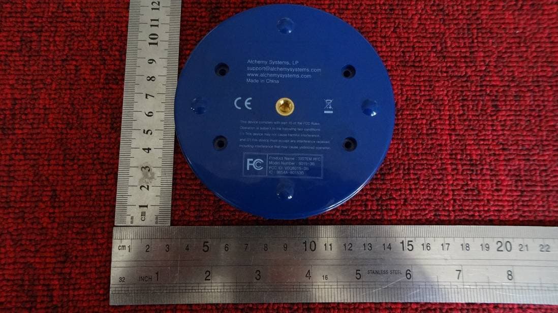
Click to zoom
Application Details
- Equipment Class
- DTS - Digital Transmission System
- Date of Grant
- Nov 07, 2013
- Application Purpose
- Original Equipment
- Date of Application
- Nov 07, 2013
- Equipment Note
- Remote control
- Frequency Range
- 2405.00000000 - 2480.00000000
- Company
- Alchemy Systems LP
- Country
- United States
Documents & Files
Document Text
Text extracted from the exhibit documents filed with the FCC. Open a document above to read the original.
Users Manual
User Manual ALCHEMY SYSTEMS LP Model:8015-3 B Manufacturer: Alchemy Systems LP RFI: Radio Frequency Remotes Request for Information Alchemy Systems L.P. 1. Introduction 1.1. Alchemy Systems L.P. Alchemy Systems LP, based in Austin, Texas, provides effective solutions for developing, delivering, and tracking critical skills training to large groups of job seekers and workers that don't typically have access to computers. Courses are delivered and managed through our unique group-based training platform or as individual e-learning courses through our enterprise-ready learning management system. Alchemy's course catalog includes highly-interactive educational media and covers topics such as job search, career readiness, industrial safety, mandated training, basic supervision and job success skills as well as industry specific training courses. 1.2. Detail Alchemy is interested in the potential of RF remote controllers for use with the SISTEM™ product. It is perceived that a change to RF remote controllers will enable SISTEM™ to meet the growing needs of our clients. The list of high-level requirements and nice-to-have requirements that Alchemy has determined would be beneficial for the SISTEM™ product are specified in the SISTEM: Integration of Radio Frequency (RF) Remotes Business Requirements document. The purpose of this document is to extend the Business Requirements document into technical specifications that will be use for the design and development of RF Remote Controls (Clickers) solution. RFI: Radio Frequency Remotes Request for Information Alchemy Systems L.P. 2. Technical Specifications SISTEM Controller Software 2.1.1. SISTEM software shall be able to link a Clicker’s unique identifier with a participant record. 2.1.2. SISTEM software; during questions answering mode; shall be able to display a list participants at the bottom of the screen for those participants that have not answered the question. This participant’s exception list will show up at the bottom of the screen after a configured percentage of the participants have casted there vote (answer). The percentage will be specified in a configuration file and shall be defaulted to 50%. This value will be able to be changed through the SISTEM administration interface. 2.1.3. SISTEM shall support a Course Management Bar (CMB) that is found at the bottom of the screen during a course. It includes several buttons for managing the participants and the course. The bar also includes visual indicators for representing the status of student responses as well as the course. See detail requirements for CMB at the Functional Specifications document date October 3, 2007 here: ( \\Scfs01\Departments\Department Public Shares\Instructional Design Public\Projects\RF Clickers\ SISTEM_RF_FS.doc ) Section 2.1.2 2.1.4. SISTEM Course Management Bar shall be used to display a list of participants that have not voted or are having problems related to remote to base station communication issues. 2.1.5. SISTEM CMB shall provide access to the Participant Management window. The purpose of the Participant Management Window is to provide roster and student management functions to course administrators during a course. The Participant Management Window includes the features specified for Option A on the functional requirements document date October 3, 2007 here: (http://www.redminealchemy.com/redmine/documents/show/17) section 2.2 : 2.1.6. SISTEM software shall support two different methods of assigning clickers to students. The selected registration method will be specified in the registration UI screen by using a checkbox called “Self Registration”. The default value of this checkbox will be stored in a configuration file and will be selected in the SISTEM administration panel. 2.1.6.1. Method one provides for assigning one clicker to one student at a time like it is done today. 2.1.6.2. Method two will support multiple participants registering/binding their remote to their participant record simultaneously. Use Case: 2.1.6.2.1. Method two will expedite the participants’ registration process to support up to 150 participants. Method two will list up to 16 student’s names at the same time. 2.1.6.2.2. Each student will have a unique clicker identification number beside their name. The clicker identification number RFI: Radio Frequency Remotes Request for Information Alchemy Systems L.P. will consist of four digits. Each digit of the number shall be 1-6 inclusive. 2.1.6.2.3. Each student will need to key in their number on the remote and SISTEM must capture the 4 key sequence for each remote to construct the pin number and match the number with a student record. 2.1.7. SISTEM software shall support multiple participants registering/binding their remote to their participant record simultaneously. This will expedited the participants’ registration process to support up to 150 participants. 2.1.8. SISTEM shall support the ability to create class roster lists. This list will reduce the people list to just the people that are scheduled for training instead of the entire employee list. This is needed to support multiple participants’ registration functionality. 2.1.9. The roster list shall be managed (create new student, select student, add and remove student)by SISTEM operator. 2.1.10. The roster list shall be stored locally on the targeted SISTEM computer. 2.1.11. The roster list shall be managed remotely via web browser. This will enable an instructor to prepare for the training session without having to leave his primary work area. Note: This requirement is deferred and will not be implemented as part of this project. 2.1.12. SISTEM software shall provide a web enabled interface exposes SISTEM administration features. This will enable the instructor to manage their work using the LMS as an alternate user interface and linking to SISTEM via a web browser to manage: 2.1.12.1. Database synchronization 2.1.12.2. Upload training records. 2.1.12.3. Web services 2…
Text truncated - open the document above for the full version.
Block Diagram
NEW-ATS-RFS-RCV BLOCKDIAGRAM Crystal 8MHz 3-LED (Green,Red,Yellow) MCU MC96FC664A EEPROM RF nRF24L01 EEPROM2Kbite Crystal 16MHz USB to UART CP2102 USB ConnectorUSB Connector
External Photos
Appearance photograph of EUT Appearance photograph of EUT Appearance photograph of EUT Appearance photograph of EUT Appearance photograph of EUT Appearance photograph of EUT
ID Label/Location Info
FCC ID: V6Q8015-3B Label Location on EUT FCC Label: Size: 20mm * 40mm Alchemy Systems LP M/N: 8015-3B FCC ID: V6Q8015-3B Alchemy Systems LP Made in China
Internal Photos
Internal photograph of EUT Internal photograph of EUT Internal photograph of EUT
Operational Description
Operational Description • This device is a data transferring System of base station. • The frequency is from 2.405GHz to 2.480GHz. • The main chips is NRF24L01. • the device designated with the following general information and technical specification as following: • Main Chipset NRF24L01 Antenna Type PCB Antenna(integral antenna) Antenna Gain 0 dBi Frequency Band 2405-2480MHz Modulation type and data rateGFSK Channel Number 26 channels Oscillating Frequency 16MHz This device could detect the signal form another device(8015-3R). it is a two-way transfer device, it could transfer with another part. RF24L01 is a single chip radio transceiver for the world wide 2.4 - 2.5 GHz ISM band. The transceiver consists of a fully integrated frequency synthesizer, a power amplifier, a crystal oscillator, a demodulator, modulator and Enhanced ShockBurst™ protocol engine. Output power, frequency channels, and protocol setup are easily programmable through a SPI interface. Current consumption is very low, only 9.0mA at an output power of -6dBm and 12.3mA in RX mode. Built-in Power Down and Standby modes makes power saving easily realizable.
Schematics
55 44 33 22 11 D D C C B B A A Delate nRESET RXD0TXD0 D-D+ VDD3.3V DGND DGND DGND VCC5V DGND DGND DGND DGNDVDD3.3V DGND VDD3.3V DGNDVCC5V DGND DGND DGND DGND DGND DGND DGND DGND nRESET 3 RXD0 3,4 TXD0 3,4 D- 4 D+ 4 TitleSize Document Number Rev Date: Sheet of <Doc> <RevCode> <Title> A3 14 Friday, May 24, 2013 TitleSize Document Number Rev Date: Sheet of <Doc> <RevCode> <Title> A3 14 Friday, May 24, 2013 TitleSize Document Number Rev Date: Sheet of <Doc> <RevCode> <Title> A3 14 Friday, May 24, 2013 C151uF/16V/2012 C11uF/16V/2012 TC2 1uF/16V/2012 C16 NC/22pF D2TVS + TC6 4.7uF/10V/2012 R84 22/1608 + TC5 4.7uF/10V/2012 C22 100nF U1 VRH3301NTX VIN 1 VSS 2 CE 3 NC 4 VOUT 5 R32 22 R85 22/1608 R31 22 D3TVS C23 100nF J1USB_SOCKET VBUS 1 D- 2 D+ 3 GND 4 C17 NC/22pF D1TVS C2 1uF/16V/2012 FB130 CP2102 U2 CP2102 DCD 1 RI 2 GND 3 D+ 4 D- 5 VDD 6 REGIN 7 VBUS 8 RST 9 SUSPEND 11 NC 10 SUSPEND 12 NC 13 NC 14 NC 17 NC 18 NC 16 NC 20 NC 15 NC 19 NC 21 NC 22 CST 23 RTS 24 RXD 25 TXD 26 DSR 27 DTR 28 EXP 29 TP6 RTS 1 R2N.C R14.7KR310K TP7 CST 1 TP1 SUSPEND 1 55 44 33 22 11 D D C C B B A A 2013.04.02Finished RF ANT MATCHING CL=12pF, 10ppm RF_IRQRF_nCSRF_SCKRF_MOSIRF_CERF_MISO nRF24L01_RF VDD3.3V VDD3.3V DGND RF_SCK 3 RF_CE 3 RF_MOSI 3 RF_MISO 3 RF_nCS 3 RF_IRQ 3 TitleSize Document Number Rev Date: Sheet of <Doc> <RevCode> <Title> A3 24 Wednesday, July 03, 2013 TitleSize Document Number Rev Date: Sheet of <Doc> <RevCode> <Title> A3 24 Wednesday, July 03, 2013 TitleSize Document Number Rev Date: Sheet of <Doc> <RevCode> <Title> A3 24 Wednesday, July 03, 2013 C7 2.2nF nRF24L01 U3 nRF24L01P CE 1 CSN 2 SCK 3 MOSI 4 MISO 5 IRQ 6 VDD1 7 VSS1 8 XC2(OUT) 9 VDD_PA(OUT) 11 XC1(IN) 10 ANT1 12 ANT2 13 VSS2 14 VSS3 17 VDD3 18 IREF 16 VSS4 20 VDD2 15 DVDD 19 EXP 21 C200.5pF E2 2.4GHz 1 R15 22 L510nH R910K C8 4.7pF BD1 30 R10 22 R12 22 C410nF R510K C3 1nF R6N.C C51.5pF L28.2nH R13 22 L13.9nH L4NC R171M R7N.C R11 22 L32.7nH BD2 30 C9 33nF C10 22pF R8N.C Y116MHz(QS-3225) R14 22 C1122pF C61.5pF R4N.C R1622K 55 44 33 22 11 D D C C B B A A MICROCONTOROLLER & DEBUG Connector(Used OCD) GUIDE HOLE Bypass Cap RESET LED CRYSTAL KEY EEPROM YELLOW RED GREEN nRESET XOUT XIN DSDADSCL SW3-TESTSW2-RESETSW1-CH SCLSDA YELLOW RED GREEN DSDA DSCL VDD18nTEST SCL SDA LPF XOUT XIN nRESET RXD2TXD2 TXD0RXD0 RF_CE RXD1 TXD1 RF_nCSRF_SCKRF_MOSIRF_MISO RF_IRQSW1-CHSW2-RESETSW3-TEST DGND DGND DGND DGND VDD3.3V DGND VDD3.3V DGND VDD3.3V DGND DGNDVDD3.3V VDD3.3V DGND DGNDDGND VDD3.3V DGNDDGND DGND DGND DGND DGND VDD3.3V RF_nCS 2 RF_SCK 2 RF_MOSI 2 RF_MISO 2 RF_IRQ 2 RF_CE 2 RXD0 1,4 TXD0 1,4 nRESET 1 TitleSize Document Number Rev Date: Sheet of <Doc> <RevCode> <Title> A3 34 Wednesday, May 22, 2013 TitleSize Document Number Rev Date: Sheet of <Doc> <RevCode> <Title> A3 34 Wednesday, May 22, 2013 TitleSize Document Number Rev Date: Sheet of <Doc> <RevCode> <Title> A3 34 Wednesday, May 22, 2013 C30 NC/250pF MC96FC664AL14LQFP-64(16X16) SPI0 SPI1 U6 MC96FC664AL14 P00/PCI00/USS0 1 P01/PCI01/ACK0 2 P02/PCI03/TXD0 3 P03/PCI03/RXD0 4 P04/PCI04/SUBXIN 5 P05/PCI05/SUBXOUT 6 P06/PCI06/SCL 7 P07/PCI07/SDA 8 P10/INT0 9 P11/INT1 10 P12/INT2 11 P13/INT3 12 P14/INT4 13 P15/INT5 14 VSS0 15 VDD0 16 P16/INT6 17 P17/INT7 18 P20/AN0/AVREF 19 P21/AN1 20 P22/AN2 21 P23/AN3 22 P24/AN4 23 P25/AN5 24 VSS1 25 VDD1 26 P26/AN6 27 P27/AN7 28 P30/USS1/AN8 29 P31/ACK1/AN9 30 P32/TXD1/AN10 31 P33/RXD1/AN11 32 P34/SSS0/AN12 33 P35/SCK0/AN13 34 P36/MOSI0/AN14 35 P37/MISO0 36 P40/USS2 37 P41/ACK2 38 P42/TXD2 39 P43/RXD2 40 P44/SSS1 41 P45/SCK1 42 P46/MOSI1 43 P47/MISO1 44 P50/BUZ 45 P51/EC0 46 P53/T1(PWM1) 48 P52/T0 47 P54/T2(PWM2) 49 P55/T3(PWM3) 50 P56/T4(PWM4) 51 P57/T5(PWM5) 52 P60/EC2 53 P61/EC3 54 nRESET 55 P62/XIN 56 P63/XOUT 57 VSS2 58 LPF 59 VDD2 60 DSCL 61 DSDA 62 nTEST 63 VDD18 64 TP13 TXD2 1 SW2 RESET 1 2 C31 NC/250pF TP14 TXD1 1 TP10GUIDE 1 TP15 RXD1 1 C18100nF SW3 CH 1 2 TP11GUIDE 1 R37NC/1K TP16 RXD2 1 R1810K R2110K R1910K C1910uF/2012 Y28MHz C32 100nF R24 22 C28 NC/100nF SW4 RESET 12 D6RED J2 HEADER2X4_2.54MM 1 2 3 4 5 6 7 8 R2210K D5GREEN R28330/1608 R29330/1608 R36 1K R20100K R30330/1608 C12 22pF C29 NC/100nF R25 22 R2310K R2610KC14100nF C33 100nF D4 1N4148 R33100K TP8GUIDE 1 SW1 TEST 1 2 C1322pF R27 22 D7YELLOW C34 100nF U5S524A GND 4 A2 3 A0 1 A1 2 SCL 6 WP 7 VCC 8 SDA 5 TP9GUIDE 1 55 44 33 22 11 D D C C B B A A UART for Debugging D-D+ RXD0TXD0 CBUS0CBUS1CBUS2CBUS3CBUS4 CBUS0 CBUS1 DGND VCC3V DGND DGND VDD5V VCC5V VDD5V VDD5V VDD5V TXD0 1,3 RXD0 1,3 D- 1 D+ 1 TitleSize Document Number Rev Date: Sheet of <Doc> <RevCode> <Title> A 44 Friday, May 24, 2013 TitleSize Document Number Rev Date: Sheet of <Doc> <RevCode> <Title> A 44 Friday, May 24, 2013 TitleSize Document Number Rev Date: Sheet of <Doc> <RevCode> <Title> A 44 Friday, May 24, 2013 + TC7 NC/10uF/16V/3216 R83 NC/22/1608 R78NC/220/1608 C21 NC/100nF TP12 CBUS2 1 LED5NC/RED TP17 CBUS3 1 R79 NC/22/1608 FT232RL U9 NC/FT232RL VCCIO 4 VCC 20 USBDM 16 USBDP 15 NC 8 RESET# 19 NC 24 OSCI 27 OSCO 28 3V3OUT 17 AGND 25 GND 7 GND 18 GND 21 TEST 26 CBUS4 12 CBUS3 14 CBUS2 13 CBUS1 22 CBUS0 23 RI# 6 DCD# 10 DSR# 9 DTR# 2 CTS# 11 RTS# 3 RXD 5 TXD 1 TP18 CBUS4 1 NC/HH600FB2 R81 NC/22/1608 R80NC/220/1608 LED6NC/RED R82 NC/22/1608
Test Report
Page 1 of 71 FCC ID TEST REPORT for Alchemy Systems LP MODEL: 8015-3B FCC ID: V6Q8015-3B Test Report Number: 1309001805E1 Issued Date: Oct. 9, 2013 Issued for: Alchemy Systems LP 8015 Shoal Creek Blvd., Suite 100 Austin Texas 78757 United States Issued By: SHENZHEN TIMEWAY TECHNOLOGY CONSULTING CO., LTD. 5/F,Block 4, Anhua Industrial Zone., No.8 Tairan Rd. Chegongmiao, Futian District Shenzhen, China TEL: +86-755-83448688 FAX: +86-755-83442996 Report No.: 1309001805E1 Issued: Oct. 9, 2013 Revised: None FCC ID: V6Q8015-3B TRF No.: FCC part 15 C/A0 Page 2 of 41. TABLE OF CONTENTS 1 TEST CERTIFICATION ....................................................................................................................... 3 2 TEST RESULT SUMMARY ............................................................................................................ 4 3 EUT DESCRIPTION ............................................................................................................................ 5 4 SETUP OF EQUIPMENT UNDER TEST AND TEST EQUIPMENTS USED ................................. 6 4.1. DESCRIPTION OF SUPPORT UNITS ................................................................................. 7 4.2. Description of Test Configuration .......................................................................................... 7 4.3. CONFIGURATION OF SYSTEM UNDER TEST .................................................................. 8 4.4. Justification .......................................................................................................................... 8 4.4. Test mode ............................................................................................................................ 8 5 FACILITIES AND ACCREDITATIONS .......................................................................................... 9 5.1. FACILITIES ........................................................................................................................... 9 5.2. MEASUREMENT UNCERTAINTY ...................................................................................... 10 ANTENNA REQUIREMENT ................................................................................................................ 11 Standard Applicable ................................................................................................................... 11 Antenna Connector Construction ............................................................................................... 11 - CONDUCTED EMISSIONS ............................................................................................................... 12 Applicable Standard ................................................................................................................... 12 Test Procedure .......................................................................................................................... 12 Environmental Conditions .......................................................................................................... 12 Plot(s) of Test Data .................................................................................................................... 12 - SPURIOUS EMISSIONS .................................................................................................................... 15 Test Equipment .......................................................................................................................... 15 Test Procedure .......................................................................................................................... 15 Environmental Conditions .......................................................................................................... 15 Radiated Test Setup .................................................................................................................. 15 Radiated Emission Limit............................................................................................................. 16 – 6DB BANDWIDTH TESTING ............................................................................................................ 25 Test Equipment .......................................................................................................................... 25 Test Procedure .......................................................................................................................... 25 Environmental Conditions .......................................................................................................... 25 Applicable Standard ................................................................................................................... 25 Test Result: Pass. ...................................................................................................................... 26 - MAXIMUM PEAK OUTPUT POWER................................................................................................. 28 Test Equipment .......................................................................................................................... 28 Test Procedure .......................................................................................................................... 28 Environmental Conditions .......................................................................................................... 28 Applicable Standard ................................................................................................................... 28 Test Result ................................................................................................................................. 29 -100 KHZ BANDWIDTH OF FREQUENCY BAND EDGE ................................................................... 30 Test Equipment .......................................................................................................................... 30 Test Procedure .........…
Text truncated - open the document above for the full version.
Test Setup Photos
CONDUCTED EMISSION TEST RADIATED EMISSION TEST BELOW 1GHZ RADIATED EMISSION TEST ABOVE 1GHZ
Contact Information
Applicant
Archie Barrett(CTO)
Test Firm
Shenzhen Timeway Testing LaboratoriesJack Chung
Technical Specifications
| # | Rule Parts | Frequency Range | Power Output |
|---|---|---|---|
| 1 | 15C | 2.40 GHz - 2.48 GHz | 1.10 mW |
Other Applications from Alchemy Systems LP
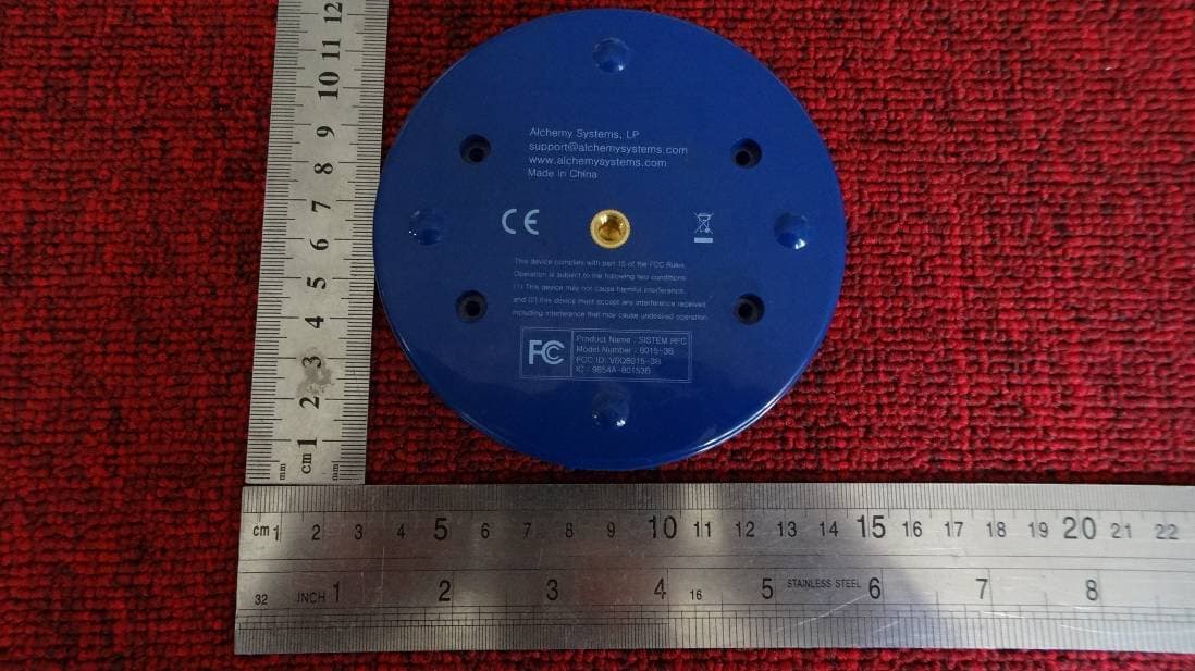
V6Q8015-3B
Nov 07, 2013Base Station
Equipment Class
DTS - Digital Transmission System