V7LWRA3WIRELESS FIRE ALARM PANEL
Simplex Time Recorder Company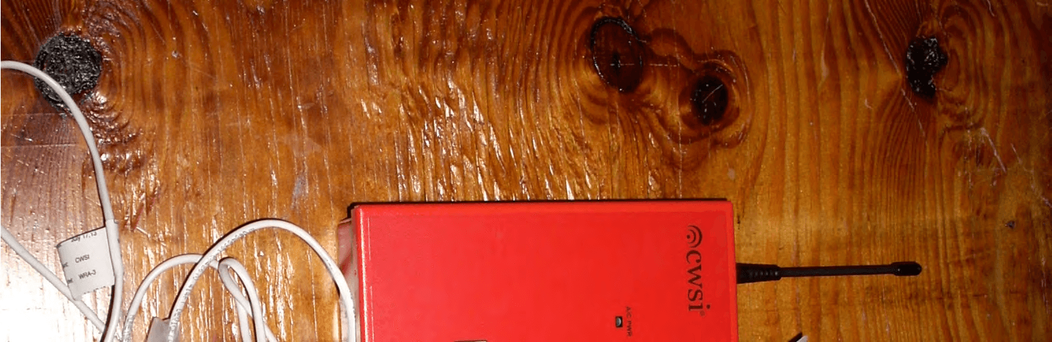
Click to zoom
Application Details
- Equipment Class
- DSS - Part 15 Spread Spectrum Transmitter
- Date of Grant
- Aug 28, 2013
- Application Purpose
- Original Equipment
- Date of Application
- Aug 28, 2013
- Equipment Note
- WIRELESS FIRE ALARM PANEL
- Frequency Range
- 904.00000000 - 926.10000000
- Country
- United States
Documents & Files
Document Text
Text extracted from the exhibit documents filed with the FCC. Open a document above to read the original.
Users Manual
P/N IM-WRA-3 Rev. A 2012 Commercial Wireless Systems International, LLC. WRA-3(R)(LG) WIRELESS REMOTE ANNUNCIATOR OPERATING and INSTALLATION INSTRUCTION MANUAL CWSI, LLC 10978 N.W. 53 Street Sunrise, Florida 33351 P/N IM-WRA-3 Rev. A 2012 Commercial Wireless Systems International, LLC. 2 Disclaimer The information contained in this document is believed to be accurate and reliable at the time of printing. Known corrections or omissions may be found on errata sheets included in the various product manuals. However, Commercial Wireless Systems International, LLC herein known as CWSI, may not be held accountable for errors or omissions in this or other CWSI publications. No license is granted by implication or otherwise under any patent rights of CWSI CWSI makes no claims as to the suitability of their products for a specific installation site or for a specific application. Local testing for suitability of both the proposed site and application is required. Unless prohibited by law, the liability of CWSI is limited to the cost of the equipment supplied by CWSI or their authorized agent. The liability of CWSI for defective product is limited to the repair or replacement of the defective product at the option of CWSI. CWSI is not liable for, nor will reimbursement be made for the removal of, or replacement of the defective equipment or for the inconvenience or supplemental costs which may be incurred by the installer, installing company, dealer or end user of the equipment. All guarantees or warranties on the products are limited to those published by CWSI and no others, given verbally or in writing are valid except when signed specifically by the president of CWSI. DISCLAIMER .................................................................................................. 2 P/N IM-WRA-3 Rev. A 2012 Commercial Wireless Systems International, LLC. 3 INTRODUCTION ............................................................................................. 4 FCC Statements ............................................................................................................ 4 FCC Warning................................................................................................................. 4 FCC Warning – RF Exposure........................................................................................ 4 SECTION 1 - DESCRIPTION AND FEATURES .............................................. 5 1.1 Product Description ...................................................................................................................... 5 1.2 Features ...................................................................................................................................... 5 1.3 Specifications............................................................................................................................... 5 SECTION 2 - COMPATIBILITY ....................................................................... 6 2.1 Compatible Equipment and Accessories ........................................................................................ 6 SECTION 3 - INSTALLATION ........................................................................ 6 3.1 Preparing the Installation Site........................................................................................................ 6 3.2 Receiving and Unpacking the Equipment ....................................................................................... 7 3.3 Installing the WRA-3 Annunciator .................................................................................................. 7 3.4 The Backup Battery ...................................................................................................................... 8 SECTION 4 – USER INTERFACES ................................................................ 9 4.1 LEDS .......................................................................................................................................... 9 4.2 LCD............................................................................................................................................. 10 4.3 Sounder....................................................................................................................................... 10 4.4 Buttons ........................................................................................................................................ 10 SECTION 5 – OPERATION ............................................................................ 11 5.1 Overview ..................................................................................................................................... 11 5.2 Normal standby ............................................................................................................................ 11 5.3 Alarm, Supervisory and Trouble annunciation ................................................................................ 11 5.4 Trouble signals............................................................................................................................. 13 5.5 Test mode ................................................................................................................................... 13 SECTION 6 – PROGRAMMING ...................................................................... 14 6.1 General ....................................................................................................................................... 14 6.2 WRA-3 Software programming tool................................................................................................ 14 6.3 Programming the WRA-3 .............................................................................................................. 14 SECTION 7 – INFO AND MAINTENANCE ..................................................... 16 7.1 Menus ........................................................................…
Text truncated - open the document above for the full version.
ID Label/Location Info
FCC Label Example Actual size 1.5” x .75 FCC ID: V7LWRA3 This device complies with Part 15 of the FCC Rules. Operation is subject to the following two conditions: (1) this device may not cause harmful interference, and (2) this device must accept any interference received, including interference that may cause undesired operation.
Test Report
Commercial Wireless Systems FCC ID: V7LWRA3Page 1 of 14 Product Safety Engineering, Inc 12955 Bellamy Brothers Blvd. Dade City, FL 33525 352-588-2209 TEST REPORT 13F128 08/23/2013 Applicant: Commercial Wireless Systems International LLC 10798 NW 53 rd Street Sunrise, Fl 33351 Product: Model - WRA3 Wireless Control Panel and Repeater In Accordance with FCC Part 15.247 Test dates: 07/11/2013 - 07/23/2013 Receive Date: 06/27/2013 Prepared by: Steven E. Hoke - EMC Site Manager This report may only be reproduced in full without written permission from Product Safety Engineering, Inc. Testing Certification # 1367-01 Commercial Wireless Systems FCC ID: V7LWRA3Page 2 of 14 Table of Contents Table of contentsPage 2 Test proceduresPage 3-4 Test SummaryPage 5 Peak Output Power Test DataPage 6 Powerline Conducted EmissionsPage 7 20 dB BandwidthPage 8 Channel SeparationPage 9 Number of Hopping FrequenciesPage 10 Dwell TimePage 11 Spurious Emissions & Restricted Band CompliancePage 12 RF ExposurePage 13 Antenna SpecificationsPage 14 Exhibit 1 - Powerline Conducted Emissions Page A1-A4 Exhibit 2 - Bandwidth PlotsPage A5 - 7 Exhibit 3 - Channel SeparationPage A8 Exhibit 4 - Number of Hopping FrequenciesPage A9-A10 Exhibit 5 - Dwell TimePage A11-A12 Exhibit 6 - Output Power & Spurious EmissionsPage A13-A28 Exhibit 7 - Antenna InformationPage A29 Commercial Wireless Systems FCC ID: V7LWRA3Page 3 of 14 Test Procedures Product description: The system utilizes FHSS type transmitters. The CWSI alarm panel and remote monitor are comprised of models CP3000 and WAR-3 respectively. The model CP3000 is a Control panel with transceiver and the WAR-3 consists of the identical transceiver as included in the CP3000 but does have any control circuitry. Powerline conducted interference: The AC powerline conducted emissions were measured. 20 dB Bandwidth: The EUT had its hopping function disabled while modulated. The spectrum analyzer span was set to (2-3) times the (20) dB bandwidth. The spectrum analyzer was placed in peak hold mode and the upper and lower points of the waveform were measured at a level that was (20) dB down from the peak amplitude. This was repeated for a low, mid and high frequency channel. Channel Separation: The EUT had its hopping function enabled. The span on the spectrum analyzer was set wide enough to capture at least (2) adjacnet channels. The channel separation was determined by measuring the peak frequency of (2) adjacent channels. Description of frequency hopping system: The system utilizes 37 channels from 902.7 MHz to 926.1MHz in the ISM band. The RF Unit hops though each of these channels at a rate of 375ms per channel, for a total hopping loop of 13.875 seconds. The system initiates data transmissions completely asynchronously from the hopping system which creates a random distribution of data for each channel. All messages are also acknowledged, which provides significant bandwidth throttling (i.e. messages can not be sent continuously) which limits duty cycle per transmitter about 50%. Due to system limitations such as a maximum payload size of 32bytes, 5khz bit rate, and a fixed 7 bytes packet overhead, the longest time a RF transmitter can be active is 78ms. All channels are used all of the time. There are not any facilities to detect jammed or undesirable channels and remove them from the hopping system. Receiver bandwidth: The system receivers shall have input bandwidths that match the hopping channel bandwidths of their corresponding transmitters and shall shift frequencies in synchronization with the transmitted signals. Number of hopping frequencies: With the spectrum analyzer in peak hold, we stored an image of all the channels operating and then produced a plot of the analyzer. We manually counted each channel to determine the number. Dwell time: The EUT had its hopping function enabled. The average time of occupancy was first determined by measuring the width of a single channel with the spectrum analyzer in a zero span mode and then with the analyzer in a peak hold mode, a (10) second sweep was then performed to determine how many single channels occupied a (10) second period of time. Commercial Wireless Systems FCC ID: V7LWRA3Page 4 of 14 RF Exposure Compliance Requirements: Systems operating under the provisions of this section shall be operated in a manner that ensures that the public is not exposed to radio frequency energy levels in excess of the Commission’s guidelines. Computations included in test report. Peak output power: The EUT had a direct connection to the measuring equipment. Conducted output power: The conducted output power was measured with a direct connection between the EUT and the spectrum analyzer. Operation with directional antenna gains greater than 6 dBi: Not applicable Spurious emissions: All spurious emissions were measured up to the tenth harmonic per ANSI C63.4:2003. Restricted Band Compliance: All emissions were measured per ANSI C63.4:2003 and compared to the restricted band list. Other conditions of operation per 15.247 15.247 (a) (1) - The system shall hop to channel frequencies that are selected at the system hopping rate from a pseudo randomly ordered list of hopping frequencies. Each frequency must be used equally on the average by each transmitter. Each transmitter hops over a pseudo-random list of 36 distinct hopping frequencies. Transmitters will remain in a frequency for 398 ms (hop period). Transmitters will hop into each frequency in the list (and remain at that frequency for the hop period) until each frequency has been “hopped into” once (hop cycle). Transmitters will start a new hop cycle once the previous one completes. 15.247 (g) - Frequency hopping spread spectrum systems are not required to employ all available hopping channels during each transmission. However, the system, consisting of both the transmitter and the receiver, must be designed to comply with all of the regulations in this section should the transmitter be pres…
Text truncated - open the document above for the full version.
Contact Information
Applicant
Martin Chiarizio(Engineering Manager)
Test Firm
TUV SUD America Inc.William Elliott
Technical Specifications
| # | Rule Parts | Frequency Range | Power Output |
|---|---|---|---|
| 1 | 15C | 904 MHz - 926.1 MHz | 3.60 mW |
Other Applications from Simplex Time Recorder Company
V7L325320
Apr 07, 2014WIRELESS FIRE ALARM PANEL
Equipment Class
DSS - Part 15 Spread Spectrum TransmitterV7L300301
Aug 20, 2008Wireless Smoke Detector
Equipment Class
DSS - Part 15 Spread Spectrum Transmitter