V7PNT-2007BLighting Controller
Winners Lighting Manufactory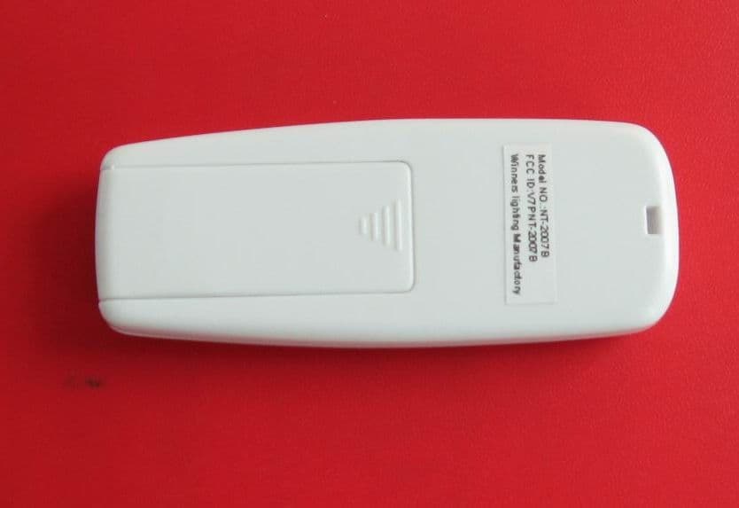
Click to zoom
Application Details
- Equipment Class
- DSC - Part 15 Security/Remote Control Transmitter
- Date of Grant
- Apr 17, 2008
- Application Purpose
- Original Equipment
- Date of Application
- Apr 17, 2008
- Equipment Note
- Lighting Controller
- Frequency Range
- 433.59000000 - 433.59000000
- Company
- Winners Lighting Manufactory
- Country
- China
Documents & Files
Document Text
Text extracted from the exhibit documents filed with the FCC. Open a document above to read the original.
Users Manual
ROMOTE- CONTROL USER MANUAL Product name:Romote-control Model:NT-2007B Winners Lighting Manufactory IntroductionThis remote control device is used to control Christmas lights. The buttons "ON" and "OFF" on the EUT are for turning the lights on and off. Remove the lid from the battery box . Plug into two 1.5V AAA battery. Battery box Lid of the battery box Then push on the lid of the battery box. Press the ‘on’ button for turning on the Christmas light, and the ‘off’ button for turning off the Christmas light. LED light ‘on’ button ‘off’ button Push off the lampshade from the light. Then plug into two 1.5V AAA battery. Lampshade LED light Then push on the lampshade . When both of the robot and the light are powered by battery, and they are in normal station, we can use them. If you want to turn on the Christmas light, you just need to press the ‘on’ button on the robot, then the light will continue to work until you press the ‘off’ button, that is for turning off the light. Federal Communication Commission Interference Statement This equipment has been tested and found to comply with the limits for a Class B digital device, pursuant to Part 15 of the FCC Rules. These limits are designed to provide reasonable protection against harmful interference in a residential installation. This equipment generates uses and can radiate radio frequency energy and, if not installed and used in accordance with the instructions, may cause harmful interference to radio communications. However, there is no guarantee that interference will not occur in a particular installation. If this equipment does cause harmful interference to radio or television reception, which can be determined by turning the equipment off and on, the user is encouraged to try to correct the interference by one of the following measures: - Reorient or relocate the receiving antenna. - Increase the separation between the equipment and receiver. - Connect the equipment into an outlet on a circuit different from that to which the receiver is connected. - Consult the dealer or an experienced radio/TV technician for help. This device complies with Part 15 of the FCC Rules. Operation is subject to the following two conditions: (1) This device may not cause harmful interference, and (2) this device must accept any interference received, including interference that may cause undesired operation. FCC Caution: Any changes or modifications not expressly approved by the party responsible for compliance could void the user's authority to operate this equipment.
External Photos
External photo of Remote-Control NT-2007B
ID Label/Location Info
The label is made by Polyster material and permanent adhesive.
Internal Photos
Internal photo of Remote-Control NT-2007B
Operational Description
ROMOTE-CONTROL OPERATIONAL DESCRIDPTION 1. Supply voltage: DC 3V 2. Frequency of operation: 433MHz 3. Number of channels: 1 4. Antenna type: Helical wire 5. Antenna gain: 0dBi 6. Antenna connector: NONE(soldered on PCB) 7. Introduction of the device: The device is used to control Christmas lights, the buttons "on" and "off" on the EUT is for turning the lights on and off. 8. Related antenna connector photo:
Test Report
FCC ID: V7PNT-2007B Report No.:080313FIA01 1 FCC TEST REPORT REPORT NO.: 080313FIA01 MODEL NO.: NT-2007B RECEIVED: Mar. 14, 2008 TESTED: Apr. 10, 2008 ISSUED: Apr. 14, 2008 APPLICANT: Winners Lighting Manufactory ADDRESS: Guangming Road,Yanhe Industrial Zone,Liwu Village,Qiaotou Town,Dongguan City,Guangdong Province,China ISSUED BY: ADT (Shanghai) Corporation ADDRESS: 2F, Building C, No.1618, Yishan rd., 201103, Shanghai, China This test report consists of 29 pages in total. It may be duplicated completely for legal use with the approval of the applicant. It should not be reproduced except in full, without the written approval of our laboratory. The client should not use it to claim product endorsement by A2LA or any government agencies. The test results in the report only apply to the tested sample. The test results in this report are traceable to the national or international standards. This report contains data that were produced under Laboratory ADT (Shanghai) Corporation. ADT (Shanghai) Corporation. V 1.0.0 FCC ID: V7PNT-2007B Report No.:080313FIA01 2 Table of Contents 1 CERTIFICATION .......................................................................................... 4 2 SUMMARY OF TEST RESULTS .................................................................. 5 2.1 MEASUREMENT UNCERTAINTY............................................................... 5 3 GENERAL INFORMATION........................................................................... 6 3.1 GENERAL DESCRIPTION OF EUT ............................................................ 6 3.2 DESCRIPTION OF TEST MODES .............................................................. 6 3.3 GENERAL DESCRIPTION OF APPLIED STANDARDS.............................. 8 3.4 DESCRIPTION OF SUPPORT UNITS ........................................................ 8 4 EMISSION TEST.......................................................................................... 9 4.1 CONDUCTED EMISSION MEASUREMENT............................................... 9 4.1.1 LIMITS OF CONDUCTED EMISSION MEASUREMENT ............................ 9 4.1.2 TEST RESULTS .......................................................................................... 9 4.2 DEACTIVATION TIME ............................................................................... 10 4.2.1 LIMITS OF DEACTIVATION TIME MEASUREMENT................................ 10 4.2.2 TEST INSTRUMENTS............................................................................... 10 4.2.3 TEST PROCEDURES ............................................................................... 10 4.2.4 DEVIATION FROM TEST STANDARD...................................................... 10 4.2.5 TEST SETUP............................................................................................. 10 4.2.6 TEST RESULTS ........................................................................................ 11 4.3 RADIATED EMISSION MEASUREMENT.................................................. 12 4.3.1 LIMITS OF RADIATED EMISSION MEASUREMENT............................... 12 4.3.2 TEST INSTRUMENTS............................................................................... 14 4.3.3 TEST PROCEDURE.................................................................................. 15 4.3.4 DEVIATION FROM TEST STANDARD...................................................... 15 4.3.5 TEST SETUP............................................................................................. 16 4.3.6 EUT OPERATING CONDITIONS .............................................................. 16 4.3.7 TEST RESULTS ........................................................................................ 17 4.4 20DB OCCUPIED BANDWIDTH MEASUREMENT .................................. 21 4.4.1 LIMITS OF BAND EDGES MEASUREMENT ............................................ 21 4.4.2 TEST INSTRUMENTS............................................................................... 21 4.4.3 TEST PROCEDURES ............................................................................... 22 4.4.4 DEVIATION FROM TEST STANDARD...................................................... 22 4.4.5 TEST SETUP............................................................................................. 22 4.4.6 TEST RESULTS ........................................................................................ 23 5 PHOTOGRAPHS OF THE TEST CONFIGURATION................................. 24 6 PHOTOGRAPHS OF THE EUT ................................................................. 25 7 APPENDIX - INFORMATION ON THE TESTING LABORATORY ............. 28 FCC ID: V7PNT-2007B Report No.:080313FIA01 3 8 APPENDIX B – UNCERTAINTY IN EMC MEASUREMENT ...................... 29 FCC ID: V7PNT-2007B Report No.:080313FIA01 4 1 CERTIFICATION PRODUCT: Remote-Control BRAND NAME: NA MODEL NO.: NT-2007B APPLICANT: Guangming Road,Yanhe Industrial Zone,Liwu Village,Qiaotou Town,Dongguan City,Guangdong Province,China TESTED: Apr. 10, 2008 TEST ITEM: Engineering Sample STANDARDS: FCC Part 15: 2007, Subpart B, Class B, Subpart C, (section 15.31, 15.109, 15.209 and 15.231) ANSI C63.4-2003 (section 7 and 8) We, ADT (Shanghai) Corporation, declare that the equipment above has been tested in our facility and found compliance with the requirement limits of applicable standards. The test record, data evaluation and Equipment Under Test (EUT) configurations represented herein are true and accurate under the standards herein specified. PREPARED BY : , DATE: Apr. 14, 2008 Lucy Tian Testing engineer TECHNICAL ACCEPTANCE: , DATE: Apr. 14, 2008 Responsible for EMI Joy Zhu Engineering Supervisor APPROVED BY : , DATE: Apr. 14, 2008 Wallace Pan Director of Operations FCC ID: V7PNT-2007B Report No.:080313FIA01 5 2 SUMMARY OF TEST RESULTS The EUT has been tested according to the following specifications: APPLIED STANDARD: FCC Part 15, Subpart C Standard Paragraph Test Type ResultRemarks 15.207 Conducted Emis…
Text truncated - open the document above for the full version.
Test Setup Photos
PHOTOGRAPHS OF THE TEST CONFIGURATION RADIATED EMISSION TEST
Contact Information
Applicant
Amy Liu
Test Firm
BUREAU VERITAS ADT (Shanghai) CorporationZhaoqian YU
Technical Specifications
| # | Rule Parts | Frequency Range | Power Output |
|---|---|---|---|
| 1 | 15.231 | 433.59 MHz - 433.59 MHz | - |