VAC7674FMFM Wireless Transmitter
SUN HEI (WORLDWIDE) ELECTRONIC CO., LTD.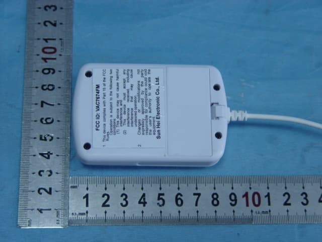
Click to zoom
Application Details
- Equipment Class
- DXX - Part 15 Low Power Communication Device Transmitter
- Date of Grant
- May 06, 2007
- Application Purpose
- Original Equipment
- Date of Application
- May 06, 2007
- Equipment Note
- FM Wireless Transmitter
- Frequency Range
- 88.10000000 - 107.90000000
- Country
- Hong Kong
Documents & Files
Document Text
Text extracted from the exhibit documents filed with the FCC. Open a document above to read the original.
Block Diagram
Audio Inpu t - Channel L Audio Inpu t - Channel R U1- Encode, Modulation, Amplification, RF Output Antenna Stereo modulation Pilo t Tone modulation synthesis RF Oscillator Amplifie r Bias XF1-38kHz Oscillator Frequency Adjust Power
ID Label/Location Info
ID label & location info. ID label location FCC ID: VAC7674FM 1. This device complies with Part 15 of the FCC Rules. Operation is subject to the following two conditions: (1) This device may not cause harmful interference, and (2) This device must accept any interference received, including interference that may cause undesired operation. 2. Changes or modifications not expressly approved by the party responsible for compliance could void the user’s authority to operate the equipment. Sun Hei Electronic Co., Ltd.
Operational Description
1) How does this device operate? The FM transmitter is a FM stereo transmitting configuration, which radiates FM wave on the air by modulating the any required signal to the carrier signal. The transmission frequency is set 88.1MHz to 107.9MHz, frequency interval is 0.1MHz. Operating Instructions: 1. Install two AAA batteries according to the indicated poles in the battery box. 2. Connect the audio cable of the transmitter to the audio-out or earphone jack of the sound source equipment(such as iPod, MP3, CD player) 3. Press the power keystoke to turn on the power and the indicator light gets light. 4. Switch 88.1M-92.0MHZ, 92.1M-98.0MHz, 98.1M-107.9MHz channel, and turn knob to adjust frequency to transmit corresponding carrier frequency. 5. Adjust the volume of the sound source equipment properly. 2) Provide information on the device and its antenna. The transmitter has seven parts: transmitter body, audio cable, power switch, channel switch, frequency adjust knob, power indicator light and battery box. The transmitter utilizes a wire as dipole antenna. The antenna are solder to PCB. Antenna 3) How is it installed? The transmitter is powered by two AAA batteries. It can be connected to audio source headphone dock. 4) What test procedure was used? ANSI C63.4, the test was performed in a semi-anechoic chamber. 5) If tested in a car, how was it configured/tested? Not tested in a car, it was tested in a semi-anechoic chamber. The EUT has been additionally tested / verified and does work in a typical car. 6) Was the tuning range properly verified? The test lab should indicate in the report that the tuning controls were manually adjusted to verify maximum tuning range. The FM transmitter is a FM stereo transmitting configuration, which radiates FM wave on the air by modulating the any required signal to the carrier signal. The transmission frequency is set from 88.1 to 107.9MHz, frequency interval is 0.1MHz. We selected the low (88.1MHz) mid (98.1MHz) and High (107.9MHz) working frequency to measure the frequency. turn the knob to select the transmission frequency . We have indicated the testing in the test report, see clause 6. 7) Was the bandwidth properly tested with maximum audio input? The test was performed with the maximum audio input. And play typical audio signal (music song). We have indicated the operating condition in the test report, see clause 5.3.
Operational Description
TX Operation Description Transmit Frequency: 88.1M-107.9MHz Modulation Type: FM 1. Audio signals are input from channel L & R. Through RC low-pass filters and coupling capacitors, the audio signals input to pin 1 and pin 18 of IC U1-BA1404. The signals are amplified and encoded inside U1 and output from pin 14. After pilot tone modulation, input to pin 12 of U1 for RF oscillating. 2. XF1 oscillator provides 38 kHz. After 1/2 division, 19 kHz is produced as pilot signal. It is synthesized with encoded signals to be stereo modulated signals. Stereo balance can be adjusted for best performance by a variable Resistor connected to Pin 16 and pin 17 of U1. 3. RF oscillating circuit consists of L2, C17, C16, VC1, pin 9 and pin 10 of U1. FM Carrier frequency and the stereo modulated signals are mixed, modulated and amplified in U1. RF signals are output from pin 7 to match network to antenna for transmission. 4. C14 and C15 are OSC capacitors for frequency selection by SW1: 88.1-92.0MHz, 92.1-98.0 MHz, 98.1-107.9 MHz. VC1 is a variable capacitor for frequency linear adjustment.
Schematics
4 3 2 1 D CBA Titl e Nu mbe r Revision Size R-CH 1 AF-BIAS 2 AF-GN D 3 OSCBIAS 4 XTAL 5 XTAL 6 RF-OUT 7 RF-GND 8 OSC 9 OSC 10 VRFE 11 MODIN 12 PILOT OUT 13 MPXOUT 14 VCC 15 MPXBLANCE 16 MPXBLANCE 17 L-CH 18 U1BA1404 R63.3K J R4 68K J R54.7K J C4 102 J C310uF/25V M J1 PHONEJ ACK STEREO R33.3K J R1 68K J R24.7K J C2 102 J C1 10uF/25V M C5 10uF/25V M C6202 J XF1 38.000K C710P J C8100P J C1927P J L3 d1*D3*T10 L15.6mH R7220R J VCC C98P J C1010P J 1 2 3 4 SW1DIP-SW-4*2 L2 d1.5*D6*T2.5 VCC C16 22P J C17 47P J VC120-30P C14 18P J C15 20P J C11222 J R8220K J C13102 J R922K J C12 10uF/25V M SW2POW R1010R J C18 220uF/10V M VCC +3V VR1 50K J D1RED R11150R J
Test Report
Page 1 of 29 FCC ID: VAC7674FM ACCURATE TECHNOLOGY CO. LTD REPORT NO. ATE20070940 FCC CERTIFICATION On Behalf of Sun Hei Electronic Co., Ltd. FM Wireless Transmitter Model No.: 7674 FCC ID: VAC7674FM Prepared for : Sun Hei Electronic Co., Ltd. Address : The third Industry District, Xiaobian, Changan Town Dongguan City, Guangdong, China Prepared by : Accurate Technology Co., Ltd. Address : F1, Bldg. A, Changyuan New Material Port, Keyuan Rd. Science & Industry Park, Nanshan, Shenzhen, Guangdong P.R. China Tel: (0755) 26503290 Fax: (0755) 26503396 Report Number : ATE20070940 Date of Test : April 25, 2007 Date of Report : April 27, 2007 Page 2 of 29 FCC ID: VAC7674FM ACCURATE TECHNOLOGY CO. LTD REPORT NO. ATE20070940 TABLE OF CONTENTS Description Page Test Report Certification 1. GENERAL INFORMATION .......................................................................................................... 4 1.1. Description of Device (EUT)....................................................................................................................4 1.2. Description of Test Facility ......................................................................................................................4 1.3. Measurement Uncertainty.........................................................................................................................4 2. MEASURING DEVICE AND TEST EQUIPMENT ..................................................................... 5 3. RADIATED EMISSION FOR FCC PART 15 SECTION 15.239(C)........................................... 6 3.1. Block Diagram of Test Setup....................................................................................................................6 3.2. The Emission Limit for section 15.239(c) ................................................................................................6 3.3. Configuration of EUT on Measurement ...................................................................................................7 3.4. Operating Condition of EUT ....................................................................................................................7 3.5. Test Procedure ..........................................................................................................................................7 3.6. The Field Strength of Radiation Emission Measurement Results ............................................................8 4. FUNDAMENTAL RADIATED EMISSION FOR FCC PART 15 SECTION 15.239(B) ........ 11 4.1. Block Diagram of Test Setup..................................................................................................................11 4.2. The Emission Limit For Section 15.239(b) ............................................................................................11 4.3. EUT Configuration on Measurement .....................................................................................................12 4.4. Operating Condition of EUT ..................................................................................................................12 4.5. Test Procedure ........................................................................................................................................12 4.6. The Emission Measurement Result ........................................................................................................13 5. OCCUPIED BANDWIDTH FOR FCC PART 15 SECTION 15.239(A) ................................... 16 5.1. The Requirement For Section 15.239(a).................................................................................................16 5.2. EUT Configuration on Measurement .....................................................................................................16 5.3. Operating Condition of EUT ..................................................................................................................16 5.4. Test Procedure ........................................................................................................................................16 5.5. Test Result ..............................................................................................................................................17 6. TUNING RANGE ........................................................................................................................... 18 6.1. The Requirement For Section 15.239 .....................................................................................................18 6.2. EUT Configuration on Measurement .....................................................................................................18 6.3. Operating Condition of EUT ..................................................................................................................18 6.4. Test Procedure ........................................................................................................................................18 6.5. Test Result ..............................................................................................................................................19 APPENDIX I ( TEST CURVES) (9pages) Page 3 of 29 FCC ID: VAC7674FM ACCURATE TECHNOLOGY CO. LTD REPORT NO. ATE20070940 Test Report Certification Applicant : Sun Hei Electronic Co., Ltd. Manufacturer : Sun Hei Electronic Co., Ltd. EUT Description : FM Wireless Transmitter (A) MODEL NO.: 7674 (B) SERIAL NO.: N/A (C) POWER SUPPLY: DC 3.0V (AAA Battery ̄2) Measurement Procedure Used: FCC Rules and Regulations Part 15 Subpart C Section 15.239: 2006& ANSI 63.4: 2003 The device described above is tested by ACCURATE TECHNOLOGY CO. LTD to determine the maximum emission levels emanating from the device. The maximum emission levels are compared to the FCC Part 15 Subpart C Section15.239 limits. The measurement results are contained in this test report and ACCURATE TECHNOLOGY CO. LTD is assumed full responsibility for the accuracy and…
Text truncated - open the document above for the full version.
Contact Information
Applicant
Chiu David(Manager)
Test Firm
Accurate Technology Co., Ltd.Sean Liu
Technical Specifications
| # | Rule Parts | Frequency Range | Power Output |
|---|---|---|---|
| 1 | 15C | 88.1 MHz - 107.9 MHz | - |
Other Applications from SUN HEI (WORLDWIDE) ELECTRONIC CO., LTD.
VAC-PDWX08
Jul 20, 20218 Inch Wi-Fi Digital Picture Frame
Equipment Class
DTS - Digital Transmission System
VAC-PDWX10
Jul 20, 202110 Inch Wi-Fi Digital Picture Frame
Equipment Class
DTS - Digital Transmission System
VACPDWX08
Aug 09, 20208 Inch Wi-Fi Digital Picture Frame
Equipment Class
DTS - Digital Transmission System
VACPDWX10
Aug 07, 202010 Inch Wi-Fi Digital Picture Frame
Equipment Class
DTS - Digital Transmission System