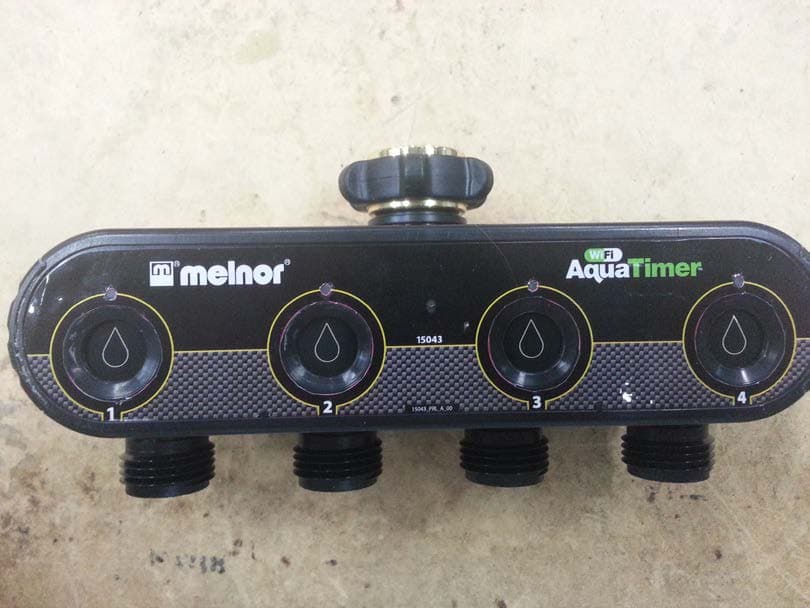
VAF-15043CWiFi Aquatimer Control Unit
Melnor, Inc.
Click to zoom
Application Details
- Equipment Class
- DTS - Digital Transmission System
- Date of Grant
- Mar 10, 2015
- Application Purpose
- Original Equipment
- Date of Application
- Mar 10, 2015
- Equipment Note
- WiFi Aquatimer Control Unit
- Frequency Range
- 915.00000000 - 915.00000000
- Company
- Melnor, Inc.
- Country
- United States
Documents & Files
Document Text
Text extracted from the exhibit documents filed with the FCC. Open a document above to read the original.
Users Manual
Copyright © 2015, Melnor, Inc. 15043_INS_E_00 1 T M TM This guide will help you connect your WiFi AquaTimer to your home WiFi network using a smartphone or tablet. After the initial setup, you can program your timer from a smart phone, tablet or computer. If at any time you need assistance, feel free to contact our support toll-free at: 844-MELNOR1 (844-635-6671) or by email at: [email protected] 2 After opening the package, please ensure you have all parts. • Valve Unit • Control Unit • Yellow Setup Tool • Power Adapter T M 3 Install batteries in the Valve Unit. You will need to supply 4 alkaline AA batteries. Ensure the battery cover is locked. Note: Do not use lithium or rechargable batteries in this product. 4 Determine the best location for the Control Unit. The Control Unit will need to be plugged in at all times. It needs to be located in an area that has good WiFi signal as well as within 200 feet of the Valve Unit. Walls, electrical equipment and other materials may affect this range. 7 On your smart device, download and install the “Melnor AquaTimer Configuration” app. Before launching the app, proceed to step 8. The app is only used to connect the timer to your home WiFi network. 6 Ensure that your smartphone or tablet is connected to the WiFi network you want to use for your WiFi AquaTimer. If not, switch your WiFi network in the smart device settings. This is for setup only. Once connected, you can control your timer from anywhere. 5 Use the included power adapter to connect the Control Unit to an indoor wall outlet. You should see flashing LED lights, alternating between “STATUS” and “CONFIG”. Setup Guide If you discover that you are missing a part, please contact us: 844-MELNOR1 or [email protected] Copyright © 2015, Melnor, Inc. 15043_INS_E_00 T M 8 Remove the Yellow Setup Tool from the bottom of the Control Unit and gently push it into the “Setup” button until the “CONFIG” light is lit solid and the “STATUS” light goes out. 13 Go to: www.wifiaquatimer.com Click on “Register” on the top menu bar. Follow the prompts to setup your account. Once registered, you will need to log in using the password you just created. Note: It is important for you to remember your login information. You will need to access this website to program and review your WiFi AquaTimer. 12 You no longer need the Melnor AquaTimer Configuration app. You can turn it off and uninstall it at anytime. If you ever need to setup your timer on another WiFi network, you can easily reinstall the app. Moving forward, everything can be completed using any web browser on a smart phone, tablet or computer. 14 The website will then prompt you to enter the serial number of your Control Unit. You can find the 12-character serial number on the back of the Control Unit. TM SSID Network Name Password xxxxxx Gateway IP Address 192.168.000.000 Start 10 Enter the network password for your WiFi home network. The app will use this information to add your WiFi AquaTimer to your WiFi home network. Press “Start”. TM SSID Network Name Password xxxxxx Gateway IP Address 192.168.000.000 Start 9 Launch the app. Beside “SSID” you should see the name of your WiFi home network. If you don’t see the correct network name, your smart device is not connected to the WiFi network. 15 Next, you enter your postal code. This information is used to provide local weather information. 11 On the Control Unit, watch for the Config light to go out and the Status light to begin flashing. This process may take several minutes. Please be patient. Congratulations, the Control Unit is now connected to your home WiFi network. Note: Depending on your network, the app may or may not confirm the connection. If the Status light has started blinking, the unit is connected. T M Copyright © 2015, Melnor, Inc. 15043_INS_E_00 Zone1Zone 2Zone 3Zone 4 Zone Start Water Water For (min) Water Every Eco Mode A zone is what is watered from one of the timer outlets. You can easily name Zones under Setup. Select the Start Time of the rst watering cycle of the day. All watering cycles must be complete by 11:59 p.m. How many minutes would you like to water? How often do you want to water? Once every 4 , 6, 8 or 12 hours -or- Once every 1, 2, 3, 4, 5, 6 or 7 days? Saves water by repeatedly opening and closing the valve during the watering cycle, allowing more soak-in and less run o . (ON/OFF) TM 15043 1234 Simple Program Use this grid to determine your watering needs before you begin programming. 16 The website will then prompt you to enter the 4-character serial number of your Valve Unit. The serial number is printed on the bottom of the unit. Press “Finish Registration”. The website will take you to the Home page. During setup, It may take a few minutes for all information to be visible on the home page. 18 The Valve Unit has four Zones or water outlets to attach hoses. Each Zone can have its own watering program. Tip: You may want to leave one outlet unprogrammed for everyday use with a hose and nozzle. To enter a program, click “Edit” under the Zone you want to program. Remember, you can now log in to your account from any smart phone, tablet or computer. 19 Watering programs can be either “Simple” or “Advanced.” The grid below is to help you plan your watering before you begin programming. For “Advanced” programming, after clicking “Edit”, change the Zone Editing Mode from “Simple” to “Advanced.” This will provide additional programming options. 17 Attach the Valve Unit to an outside faucet. Firmly tighten the coupling nut. Do not overtighten. Turn the faucet on and leave it on while the timer is in place. Attach a hose to each outlet you want to use. You can then attach sprinklers, soaker hoses or drip style watering systems. TM 15043 1234 Copyright © 2015, Melnor, Inc. 15043_INS_E_00 Zone1Zone 2Zone 3Zone 4 Zone A zone is what is watered from one of the timer outlets. You can easily name Zones under Setup. Watering Mode Select Day(s) to Water Select from Multi…
Text truncated - open the document above for the full version.
ID Label/Location Info
All labels to be of the following material/description: (1) Thermal Transfer Industrial Vinyl Laminated Label (2) Black on White Extra ‐ Strength Adhesive Label Tape
Internal Photos
Internal Photos Melnor Inc 1 | Page WLL 13637
RF Exposure Info
Certificates and reports shall not be reproduced except in full, without the written permission of Washington Labs, Limited. Maximum Permissible Exposure Evaluation For the Melnor, Inc. Wi-Fi Aquatimer Control Unit (Model 15043C) FCC ID: VAF-15043C IC ID: 7111A-15043C December 22, 2014 Revised March 9, 2015 WLL Report: 13637-MPE Rev 2 Prepared for: MELNOR, INC. 109 TYSON DRIVE WINCHESTER, VA 22603 Prepared by: WASHINGTON LABORATORIES, LTD. 7560 LINDBERGH DRIVE GAITHERSBURG, MARYLAND 20879 Testing Certificate AT-1448 Melnor, Inc. Wi-Fi Aquatimer CU RF Exposure Test Report December, 2014 WLL Report #13637-MPE Rev 2 - ii - © 2015 Washington Laboratories, Ltd. Maximum Permissible Exposure Evaluation For the Melnor, Inc. Wi-Fi Aquatimer Control Unit (Model 15043C) December 22, 2014 Revised March 9, 2015 WLL Report # 13637-MPE Rev 2 Prepared by: Steven Dovell Compliance Engineer Reviewed by: John P. Repella EMC & Wireless Lab Manager Melnor, Inc. Wi-Fi Aquatimer RF Exposure Test Report December, 2014 WLL Report #13637-MPE Rev 2 - iii - © 2015 Washington Laboratories, Ltd. Abstract This report has been prepared on behalf of Melnor, Inc. Wi-Fi Aquatimer Control Unit to document the findings of the maximum permissible exposure evaluation on the Melnor, Inc. Wi-Fi Aquatimer Control Unit. The purpose of this evaluation is to establish a minimum safe distance as per the RF exposure requirements as defined in FCC §1.1307 & §1.1310. This report documents the results of testing to the requirements of: CFR Title 47 Volume 1 Practice and Procedure; (1.1307) Environmental Assessments The Evaluation was performed by Washington Laboratories, Ltd, 7560 Lindbergh Drive, Gaithersburg, MD 20879. Washington Laboratories, Ltd. has been accepted as an EMC Conformity Assessment Body (CAB) under the United States/European Union Memorandum of Agreement. Washington Laboratories, Ltd. is accredited by ACLASS under Testing Certificate AT-1448. Revision History Reason Date Rev 0 Initial Release December 22, 2014 Rev 1 Added model number 15043C to report March 3, 2015 Rev 2 Added note about approved module FCCID Z64-CC3000EM to device summary statement. March 9, 2015 Melnor, Inc. Wi-Fi Aquatimer RF Exposure Test Report December, 2014 WLL Report #13637-MPE Rev 2 - iv - © 2015 Washington Laboratories, Ltd. Table of Contents Abstract .................................................................................................................................................................... ii 1 Introduction ................................................................................................................................................ 1 2 Requirements .............................................................................................................................................. 1 2.1 Transmitter Categories ............................................................................................................................. 1 2.2 Exposure Categories ................................................................................................................................ 1 3 Device Summary ......................................................................................................................................... 3 4 Radio Frequency Radiation Exposure Evaluation .................................................................................. 3 List of Tables Table 1: MPE Limits ..................................................................................................................................................2 Table 2: Device Summary of the Wi-Fi Aquatimer Control Unit ..............................................................................3 Table 3: Transmitter MPE Calculation Summary ......................................................................................................4 Melnor, Inc. Wi-Fi Aquatimer RF Exposure Test Report December, 2014 WLL Report #13638-MPE Rev 2 - Page 1 of 4 - © 2015 Washington Laboratories, Ltd. 1 Introduction This report has been prepared on behalf of Melnor, Inc. Wi-Fi Aquatimer Control Unit Transmitter to show compliance with the RF exposure requirements as defined in FCC §1.1307. Testing supporting this evaluation was performed at Washington Laboratories, Ltd, 7560 Lindbergh Drive, Gaithersburg, MD 20879. Washington Laboratories, Ltd. has been accepted as an EMC Conformity Assessment Body (CAB) under the United States/European Union Memorandum of Agreement. Washington Laboratories, Ltd. is accredited with ACLASS under Testing Certificate AT-1448. 2 Requirements Three different categories of transmitters are defined by the FCC in OET Bulletin 65. These categories are fixed installation, mobile, and portable. Additionally, the FCC categorizes the use of the devices based on the user’s awareness and the ability to exercise control over his or her exposure. The two categories are defined as Occupational/Controlled Exposure and General Population/Uncontrolled Exposure. 2.1 Transmitter Categories 2.1.1 Fixed Installations A fixed location means that the device, including its antenna, is physically secured at a permanent location and is not able to be easily moved to another location. Additionally, distance to humans from the antenna is maintained to at least 2 meters. 2.1.2 Mobile Devices A mobile device is defined as a transmitting device designed to be used in other than fixed locations and to be generally used in such a way that a separation distance of at least 20 centimeters is normally maintained between the transmitter's radiating structures and the body of the user or nearby persons. Transmitters designed to be used by consumers or workers that can be easily re-located, such as a wireless modem operating in a laptop computer, are considered mobile devices if they meet the 20 centimeter separation requirement. The FCC rules for evaluating mobile devices for RF compliance are found in 47 CFR §2.1091. 2.…
Text truncated - open the document above for the full version.
Test Report
Certificates and reports shall not be reproduced except in full, without the written permission of Washington Laboratories, Limited. FCC & Industry Canada Certification Test Report For the Melnor, Inc. Wi-Fi Aquatimer Control Unit (Model 15043C) FCC ID: VAF-15043C IC ID: 7111A-15043C WLL JOB# 13637-01 Rev 2 December 22, 2014 Revised March 11, 2015 Prepared for: Melnor, Inc. 109 Tyson Drive Winchester, VA 22603 Prepared By: Washington Laboratories, Ltd. 7560 Lindbergh Drive Gaithersburg, Maryland 20879 Testing Certificate AT-1448 Melnor, Inc. Wi-Fi Aquatimer CU FCC Certification Test Report December, 2014 WLL Report #13637-01 Rev 2 - ii - © 2015 Washington Laboratories, Ltd. FCC & Industry Canada Certification Test Report for the Melnor, Inc. Wi-Fi Aquatimer Control Unit (Model 15043C) FCC ID: VAF-15043C IC ID: 7111A-15043C December 22, 2014 Revised March 11, 2015 WLL JOB# 13637-01 Rev 2 Prepared by: ___________________________ Steven Dovell Compliance Engineer Reviewed by: ____________________________ John P. Repella EMC & Wireless Lab Manager Melnor, Inc. Wi-Fi Aquatimer CU FCC Certification Test Report December, 2014 WLL Report #13637-01 Rev 2 - iii - © 2015 Washington Laboratories, Ltd. Abstract This report has been prepared on behalf of Melnor, Inc. to support the attached Application for Equipment Authorization. The test report and application are submitted for a Digital Transmission System (DTS) Transmitter under Part 15.247 (10/2013) of the FCC Rules and Regulations and Spectrum Management and Telecommunications Policy RSS-210 issue 8 of Industry Canada. This Certification Test Report documents the test configuration and test results for the Melnor, Inc. Wi-Fi Aquatimer Control Unit. Testing was performed on an Open Area Test Site (OATS) of Washington Laboratories, Ltd, 7560 Lindbergh Drive, Gaithersburg, MD 20879. Site description and site attenuation data have been placed on file with the FCC's Sampling and Measurements Branch at the FCC laboratory in Columbia, MD. The Industry Canada OATS numbers are 3035A-1 and 3035A-2 for Washington Laboratories, Ltd. Site 1 and Site 2, respectively. Washington Laboratories, Ltd. has been accepted by the FCC and approved by ACLASS under Certificate AT-1448 as an independent FCC test laboratory. The Melnor, Inc. Wi-Fi Aquatimer Control Unit complies with the limits for a Digital Transmission System (DTS) Transmitter device under FCC Part 15.247 and Industry Canada RSS-210. Revision History Description of Change Date Rev 0 Initial Release December 22, 2014 Rev1 Changed model in Table 1 to 15043C March 3, 2015 Rev 2 Removed references to Frequency hopping March 11, 2015 Melnor, Inc. Wi-Fi Aquatimer CU FCC Certification Test Report December, 2014 WLL Report #13637-01 Rev 2 - iv - © 2015 Washington Laboratories, Ltd. Table of Contents Abstract ........................................................................................................................................... ii 1 Introduction ..........................................................................................................................1 1.1 Compliance Statement .................................................................................................... 1 1.2 Test Scope ....................................................................................................................... 1 1.3 Contract Information ....................................................................................................... 1 1.4 Test Dates........................................................................................................................ 1 1.5 Test and Support Personnel ............................................................................................ 1 1.6 Abbreviations .................................................................................................................. 2 2 Equipment Under Test .........................................................................................................3 2.1 EUT Identification & Description .................................................................................. 3 2.2 Test Configuration .......................................................................................................... 3 2.3 Testing Algorithm ........................................................................................................... 3 2.4 Test Location .................................................................................................................. 4 2.5 Measurements ................................................................................................................. 4 2.6 Measurement Uncertainty ............................................................................................... 4 3 Test Equipment ....................................................................................................................6 4 Test Summary ......................................................................................................................7 5 Test Results ..........................................................................................................................8 5.1 Occupied Bandwidth:...................................................................................................... 8 5.2 RF Power Output: ......................................................................................................... 10 5.3 Power Spectral Density ................................................................................................. 12 5.4 Conducted Spurious Emissions at Antenna Terminals ................................................. 13 5.5 Radiated Spurious Emissions:....................................................................................... 20 5.6 Receiver Radiated Spurious Emissions ........................................................................ 22 5.7 AC Conducted Emissions ..........…
Text truncated - open the document above for the full version.
Test Setup Photos
1 | Page WLL 13637 Test Setup Photos Melnor Inc 2 | Page WLL 13637 3 | Page WLL 13637
Contact Information
Applicant
Juergen Nies(President & CEO)
Technical Contact
Washington Laboratories, Ltd.Steven Koster
[email protected]3012161500
7560 Lindbergh Drive · Gaithersburg, Maryland · United States
Test Firm
Washington Laboratories, Ltd.Steve Koster
Technical Specifications
| # | Rule Parts | Frequency Range | Power Output |
|---|---|---|---|
| 1 | 15C | 915 MHz - 915 MHz | 6.07 mW |
Other Applications from Melnor, Inc.
VAF-15043V
Mar 10, 2015WiFi Aquatimer Valve Unit
Equipment Class
DTS - Digital Transmission System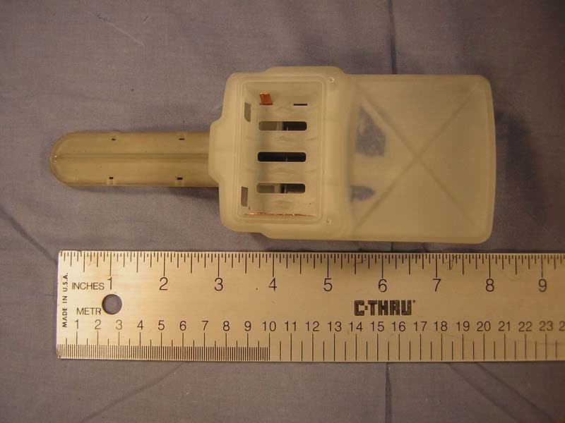
VAF3300-1
Oct 23, 2007Moisture Sensor
Equipment Class
DXX - Part 15 Low Power Communication Device Transmitter