VALPC-1015PLong Range RFID System
Boryeu Technology Co., Ltd.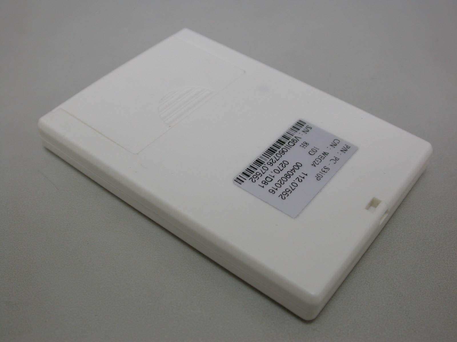
Click to zoom
Application Details
- Equipment Class
- DSR - Part 15 Remote Control/Security Device Transceiver
- Date of Grant
- May 28, 2007
- Application Purpose
- Original Equipment
- Date of Application
- May 28, 2007
- Equipment Note
- Long Range RFID System
- Frequency Range
- 433.92000000 - 433.92000000
- Company
- Boryeu Technology Co., Ltd.
- Country
- Taiwan
Documents & Files
Document Text
Text extracted from the exhibit documents filed with the FCC. Open a document above to read the original.
Users Manual
PC-SAFE Long Range RFID Reader User’s Manual PC-1015CR VER 2.1 2007.1.18 1 Index Appearance Guide .................................................................. 2 Setup Guide .................................................................. 3 Installation Guide .................................................................. 4 Installer & User’s Notice .................................................................. 8 Reader Adjustment .................................................................. 10 Troubleshooting .................................................................. 11 Warrantee .................................................................. 11 2 Appearance Guide Long Range RFID Reader Antenna Speaker LED Signals Signal Connect Joint Signal Connect Joint 3 Setup Guide Long Range RFID Reader DC12V 3.0A Power Input Antenna Input Relay Out 1 6 PIN排針 Relay Relay Relay Relay Relay Relay Relay Relay NO Battery NC COM NO NC COM NONC COM NO NC COM N O NC COM NO NC COM NO NC COM NO NC COM NO IN4 IN3 IN2 IN1B A DI 1 61 0 G 1 Relay Out 2 Relay Out 3 ~ Relay Out 8 DI 2RS-485 RS-232 (1) Speaker Wiegand 26 bit Switch RS-232 (2) 1 2 3 4 5 6 7 8 25 4 3 6 PIN = LED Signal,Wire colors :Red Light (1 Red 2 Black) Yellow Light (3 Yellow 4 Black) Green Light (5 Green 6 Balack) Relay Out 1 = Open Gate Signal Relay Out 2 = Close Gate Signal Relay Out 3 ~ Relay Out 8 = Billboard (or LED) Signal Output , total of 6 status output DI 1 = “Wake-up” Digital Input ( Must be connected ) DI 2 = “ Door Closing” Digital Input ( Must be connected to the Gate or Closing Loop ) RS485 = Link to Controller RS232 (1) = Link to LED Billboard or other indicating interface RS232 (2) = Data Output Switch = Sensitivity Switch Speaker = Embedded speaker with 5 voice indications Articulation` = Pass、Invalid、Anti-Pass Error、Fail、Low Battery Wiegand 26 bit = Data Output 4 Installation Guide 1 Antenna( (( (Pillar) )) ) 1. Lock the U-ring to the Base Plate on the Pole (2 Inches in Diameter).(Fig. 1) 2. Fix the Antenna to the Base Plate.(Fig. 2) Fig.1 Fig. 2 ( (( ( Wall ) )) ) 1. Screw the Base Plate on the Wall. ( Fig. 1 ) 2. Fix the Antenna on the Base Plate. ( Fig. 2 ) Fig 1. Fig. 2 5 2 Long Range RFID Reader and Antenna 1. Once completed the setup of the reader, fix the cap as indicated in Fig. 1. 2. Link the Signal Wire of the reader and antenna together. (Fig.2 and Fig.3) 3. Be sure the length between both reader and antenna are within 3 meters for the best performance. 4. The signal wire provided will be 3 meters long, cut it if it’s too long. DO NOT ROUND IT UP, it reduce efficacy. 5. Do not put the reader into metallic cases. Fig. 1 Fig. 2 Fig. 3 1. Screws are numbered. 2. Fix them according to their No. 1 Screw No. 2 Screw No. 3 Screw No. 4 Screw Standard wire is 3 meters long, cut able. Do not round the wires. Standard wire is 3 meters long, cut able. 6 3. Finding the most effective range of the Reader. 1. After installing the reader, refer to fig. 1 and 2 finding the most effective sensitivity range. Fig. 1 Wall Effective Range 4m 3 . 5 m 3 . 5 m 60 degree Holder Antenna Birds Eye View Fig. 2 Wall A c t u a l S e n s i t i v i t y Antenna Side View Holder Ground 4 . 2 4 2 6 m 3.0m 3.0m 4. The best angle between Reader and Card 7 1. While installing the antenna please make sure to adjust angle for it to become FACE to FACE PARALLEL with the card. (fig. 1) 2. Please put the card into the cardholder, and stick it onto the top-left or the top-right corner of the windscreen. 3. If the antenna was placed at the LEFT side of the card, stick the card on the TOP-RIGHT corner of the windscreen for the best efficacy. (fig. 2) 4. If the antenna was placed at the RIGHT side of the card, stick the card on the TOP-LEFT corner of the windscreen for the best efficacy. (fig. 3) FIG. 1 FIG. 2 FIG. 3 Installer’s Notice Antenna and Card should be FACE TO FACE. Antenna at LEFT:Card at TOP-RIGHT Antenna at RIGHT:Card at TOP-LEFT 8 1. The reader does not store history data and data comparison. 2. The product must be linked to a controller. 3. If the system used other branded Wiegand 26 bit controller, the reader may only transfer data (card id). 4. If the system uses Boryeu’s controller, thus the reader becomes more functional. Including alternating reading time in different readers, voice indication, LED Billboard and controlling the “open/close” of gates. 5. The standard system MUST link with an external sensor to activate the reader, e.g. IR, loop and ultrasound sensors etc. (If “always sensing” reader wanted, please state it when ordering.) 6. When the reader receives an external sensor signal, it would be activated once for 4 seconds. If the reader sensed a card within the timeframe it would be deactivated automatically, and waiting for the next signal. If no card was sensed during the timeframe, the reader would repeat itself once again (DI 2 must be connected) . 7. If two readers are installed on one pathway (in and out), please turn on the anti-colliding function for the system to work fluently. 8. Please do not install the antenna on metallic surfaces, or covering the reader in metallic cases. These may cause the system to work abnormally. 9. Please use the alloy holder when installing the antenna preventing the metallic substances inside the wall affecting the RF. 10. Make sure the power supply is at least 1m away from the reader. 11. Do not install the reader near any machines that gives out electromagnetic waves. 12. Please make sure the card and the antenna is at an angle FACE TO FACE to provide the best efficacy. 13. When installing the reader, please remember to be user friendly by setting the antenna on one side in both directions. Either all right or left. 14. Please make sure the antenna is 2.5 – 3m above ground, and use the holder adjusting to the perfect angle. 15. When installing the reader outdoor, please put it in a waterproof case (non-metallic). User’s Notice 1. All user should use a card holder…
Text truncated - open the document above for the full version.
External Photos
ETC Report No.: 07-03-MAS-166-02 Page A1 of A1 FCC ID.: VALPC-1015P ANNEX A: EXTERNAL CONSTRUCTION PHOTOS OF EUT 1. Outside view 1 of EUT 2. Outside view 2 of EUT
Internal Photos
ETC Report No.: 07-03-MAS-166-02 Page B1 of B2 FCC ID.: VALPC-1015P ANNEX B: INTERNAL CONSTRUCTION PHOTOS OF EUT 1. Inside View 1 of EUT 2. Inside View 2 of EUT ETC Report No.: 07-03-MAS-166-02 Page B2 of B2 FCC ID.: VALPC-1015P 3. Front view of PCB 4. Rear view of PCB
Test Report
ETC Report No. : 07-03-MAS-166-02 Sheet 1 of 25 Sheets FCC ID.: VALPC-1015P Rev. No 1.0 CONFORMANCE TEST REPORT FOR FCC 47 CFR, Part 15 Subpart B & Subpart C Report No.: 07-03-MAS-166-02 Client: Boryeu Technology Co., Ltd Product: Long Range RFID System Model: PC-1015CR FCC ID: VALPC-1015P Manufacturer/supplier: Boryeu Technology Co., Ltd Date test item received: 2007/03/20 Date test campaign completed: 2007/04/19 Date of issue: 2007/05/07 The test result only corresponds to the tested sample. It is not permitted to copy this report, in part or in full, without the permission of the test laboratory. Total number of pages of this test report: 25 pages Total number of pages of photos: External photos 1 pages Internal photos 2 pages Setup photos 2 pages Test Engineer Checked By Approved By Eric Lin James Joe Hsieh ELECTRONICS TESTING CENTER, TAIWAN NO.8, LANE 29, WENMING RD., LESHAN TSUEN, GUISHAN SHIANG, TAOYUAN COUNTY, TAIWAN 33383, R.O.C. TEL: (03) 3276170~4 INT: +886-3-3276170~4 FAX: (03) 3276188 INT: +886-3-3276188 ETC Report No. : 07-03-MAS-166-02 Sheet 2 of 25 Sheets FCC ID.: VALPC-1015P Rev. No 1.0 Client : Boryeu Technology Co., Ltd Address : 6F-2, No.189, Sec.2, Keelung Rd., Sinyi District, Taipei City 110, Taiwan. Manufacturer : Boryeu Technology Co., Ltd Address : 6F-2, No.189, Sec.2, Keelung Rd., Sinyi District, Taipei City 110, Taiwan. EUT : Long Range RFID System Trade name : PC-SAFE Model No. : PC-1015CR Power Source : 6V DC Regulations applied : FCC 47 CFR, Part 15 Subpart B & Subpart C (2006) Test Specifications : Class B The testing described in this report has been carried out to the best of our knowledge and ability, and our responsibility is limited to the exercise of reasonable care. This certification is not intended to believe the sellers from their legal and/or contractual obligations. The compliance test is only certified for the test equipment and the results of the testing report relate only to the item tested. The compliance test of this report was conducted in accordance with the appropriate standards. It’s not intention to assure the quality and performance of the product. This report shall not be reproduced except in full, without the approval of ETC. This report must not be used by the client to claim product endorsement by NVLAP or any agency of the U.S. Government. Laboratory Introduction: Electronics Testing Center, Taiwan is recognized, filed and mutual recognition arrangement as following: 1 ISO9001: TüV Product Service 2 ISO/IEC 17025: BSMI, CNLA, DGT, NVLAP, CCIBLAC, UL, Compliance 3 Filing: FCC, Industry Canada, VCCI 4 MRA: Australia, Hong Kong, New Zealand, Singapore, USA, Japan, Korea, China, APLAC through CNLA 5 FCC Registration Number: 90588, 91094, 91095 NVLAP Lab Code 200133-0 ETC Report No. : 07-03-MAS-166-02 Sheet 3 of 25 Sheets FCC ID.: VALPC-1015P Rev. No 1.0 Table of Contents Page 1. GENERAL INFORMATION ......................................................................................................................................4 1.1 PRODUCT DESCRIPTION.................................................................................................................................................4 1.2 CHARACTERISTICS OF DEVICE: ......................................................................................................................................4 1.3 TEST METHODOLOGY....................................................................................................................................................4 1.4 TEST FACILITY...............................................................................................................................................................4 2. DEFINITION AND LIMITS........................................................................................................................................5 2.1 DEFINITION....................................................................................................................................................................5 2.2 RESTRICTED BANDS OF OPERATION...............................................................................................................................5 2.3 LIMITATION....................................................................................................................................................................6 2.4 LABELING REQUIREMENT..............................................................................................................................................7 2.5 USER INFORMATION.......................................................................................................................................................7 3. SYSTEM TEST CONFIGURATION..........................................................................................................................8 3.1 EUT CONFIGURATION AND OPERATING..........................................................................................................................8 3.2 DEVICES FOR TESTED SYSTEM.......................................................................................................................................8 3.3 DEVIATION STATEMENT.................................................................................................................................................8 3.4 MODIFICATION RECORD.................................................................................................................................................8 4. RADIATED EMISSION MEASUREMENT..............................................................................................................9 4.1 APPLICABLE STANDARD.................................................................................................................................................9 4.2 MEASUREMENT PROCEDURE.............................................................................................…
Text truncated - open the document above for the full version.
Test Setup Photos
ETC Report No.:07-03-MAS-166-02 Sheet 1 of 2 Sheets FCC ID.: VALPC-1015P Radiated Measurement Photos 433MHz TX and 125 kHz RX x-axis ETC Report No.:07-03-MAS-166-02 Sheet 2 of 2 Sheets FCC ID.: VALPC-1015P ETC Report No.:07-03-MAS-166-02 Sheet 3 of 2 Sheets FCC ID.: VALPC-1015P y-axis z-axis
Contact Information
Applicant
Paul Hsuei(Marketing Manager)
Test Firm
Electronics Testing Center, TaiwanWinpo Tsai
Technical Specifications
| # | Rule Parts | Frequency Range | Power Output |
|---|---|---|---|
| 1 | 15.231 | 433.92 MHz - 433.92 MHz | - |
Other Applications from Boryeu Technology Co., Ltd.
VALPC-1015R
May 29, 2007Long Range RFID System
Equipment Class
DCD - Part 15 Low Power Transmitter Below 1705 kHz