VAUGC527444GSM AUTO SECURITY SYSTEM
4G Technologies LLC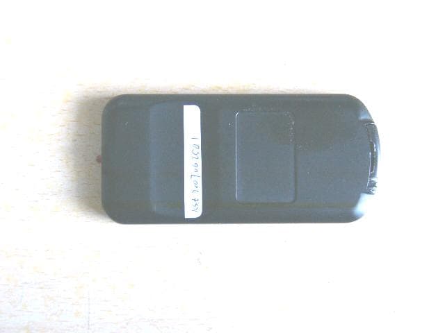
Click to zoom
Application Details
- Equipment Class
- DSC - Part 15 Security/Remote Control Transmitter
- Date of Grant
- Oct 21, 2007
- Application Purpose
- Original Equipment
- Date of Application
- Oct 21, 2007
- Equipment Note
- GSM AUTO SECURITY SYSTEM
- Frequency Range
- 433.99000000 - 433.99000000
- Company
- 4G Technologies LLC
- Country
- United States
Documents & Files
Document Text
Text extracted from the exhibit documents filed with the FCC. Open a document above to read the original.
Users Manual
GSM Auto Security GSM Auto Security User’s manual Model No.T360-500 CONTENTS Product overview......................................................... 1 Product components...................................................... 2 Detail functions introduction............................................. 3 1. Wireless keyboard operation....................................... 5 2. Phone operations...................................................... 5 3. Alarm.................................................................. 9 4. Auto function......................................................... 10 5. LED indicator...................................................... 10 6. Function of existing or factory – installed remote transmitters......................................................... 11 7. GSM Car mobile phone.......................................... 11 Notices ........................................................................ 11 Index parameter............................................................ 12 Installation notices......................................................... 13 Common problems & solutions ....................................... 13 Installation wiring Diagram 1、Wiring Diagram for base unit.................................... 15 2、Central lock Wiring Diagram.................................... 16 3、Compatibility Wiring Diagram................................. 17 3﹑Compatibility Wiring Diagram -17- 2、Central lock wiring diagram -16- △ This operation instructions is for T360-500, please read them before use Product overview Amwell GSM auto security System is the new version of car one-way or two-way alarms system. Which combines the GSM mobile communication, GSM locating technology and MECROCHIP rolling code technology, multi-code mating and microcomputer technology. The car owners can control the car remotely by cell phone in anywhere. The system can call emergency help to the mobile or fixed phone automatically. The functions of Amwell GSM auto security system 1. Ensure the safety of company and personal vehicles 2. Prevent the occurrences of crimes to vehicles 3. Decrease the compensation of insurance 4. Alarming in time 5. Be convenient for taxi and transportation companies to manage vehicles Protect Your Car Anywhere or Anytime -1- Product components T360-500:one base unit ,one wireless remote keyboard, one shock sensor, siren, loudspeaker, one antenna, one relay, one emergency button, one LED indicator , microphone ,12 PIN harness,10PIN harness, user manual. The identification for the main parts. I:The base unit < Please refer to the wiring diagram of installation and install accordance with requirement > II:Identification for wireless keyboard < The pictures for wireless keyboard is only for your reference, the real appearance subjects to practicality -2- Installation wiring Diagram 1、Wiring Diagram for base unit -15- (1) Check whether GSM signal is OK. (2) Check Whether SIM Card touches properly. (3) Check whether cut off the power source and the back-up battery when inserting the GSM card. (4)Open the ACC, meanwhile press the emergency button for 5 times, direction lights flash 3 times, the system will reset again Problem 2: Calling the controlling phone numbers when there is no alarm triggered Solution: (1) Check if the shake sensitivity is too high. (2) Check if the door lock/unlock switch is OK. (3) Check if the battery has enough power or touch well. Problem 3: The central lock can’t lock automatically when driving Solution: (1) Whether the door is completely closed. (2) Whether the connection of central lock is OK. (3) Whether the car battery has enough power or touches well. Problem 4: The user can’t start the car under system disarmed status Solution: (1) Check if back-up battery has enough power. (2) Check if the engine connection is OK. Our company reserves the rights to amend product performance index & function without notice in advance. -14- Planform for accessories -3- Speed operation instruction -4- (5) Working temperature Base unit: storage in -30~+85°C Working temperature: -20~+75°C Working humidity: 25%~95% Accessories: storage in -40~+100°C Working temperature: -20~+85°C Working humidity: 25%~95% (6) Dimension of base unit T360-500: 120mm*83mm*35m Installation notices (1) First, make sure that the back-up battery is off. Use tools to take out the SIM card slot, insert the SIM card into it according to the shape of the card slot and then put it into base unit The host device is electronic compressor lock after factory, Please contact with the factory if need the gas compressor lock. (2)Connect with Power First, connect with the 12V main power source. Observe that LED indicates GSM signals or not Open the back-up battery. (3) Function check Set up controlling phone numbers Test the alarming Common problems & solutions Problem 1.Car phone is Power off when call the system Solution: -13- 3. Check the remained money of the SIM card in time 4. Keep vehicles under the signal of GSM. 5. Secret the password of the main unit. Change the password once it is disclosed 6. Under the system is armed status, owner can not be opened the door and start engine with key, if owner do these action, system will alarm; After arm system by phone., system can only be disarm by phone 7. It is dangerous to stop the vehicle when it is running fast, system will ask user to confirm. Suggest notifying the driver before using this function ,first the user can warn the driver and give him some time to respond ,if no danger ,then stop the car running Index parameter (1) Base unit Working voltage: 12V Static current: 40mA-60mA Working frequency when arming and disarming: 400MHz-433MHz Cover scope: same as the GSM Time for alarming: It lasts till system disarmed or the alarming call answered by someone (2) Output voltage of control interface Stop engine voltage: 0V Control oil line voltage: 0V Control loudspeaker voltage: 12V (3) Input voltage Checking door s…
Text truncated - open the document above for the full version.
Users Manual
Warning FCC regulations state that: 1. The Grantee of a license has the responsibility of assuring that all equipment operated under that license confirms to the specifications of the license. 2. The RF power output of a radio transmitter shall be no more than that required for satisfactory technical operation considering the area to be covered and local conditions. 3. The frequency, deviation, and power of a radio transmitter must be maintained within specified limits. It is recommended, therefore, that these three parameters be checked before the station is placed in service. REMEMBER The efficiency of the equipment depends upon a good installation. Manufacturer recommends that adjustments to this equipment be made ONLY by a certified technician. CAUTION Changes or modifications not expressly approved by the party responsible for compliance could void the user's authority to operate the equipment. The equipment accessories are approved by FCC and only accessories from Manufacturer are qualified for this equipment applications. Detail information see FCC part 15.27. IMPORTANT (a) Only shielded cables, antennas, and special connectors from Manufacturer can be used in this system. Information detailing any alternative method used to supply the special accessories shall be must be approved by FCC and included in the application for a grant of equipment authorization or retained in the verification records, as appropriate. The party responsible for the equipment shall ensure that these special accessories are provided with the equipment. The instruction manual for such devices shall include appropriate instructions on the first page of the text concerned with the installation of the device that these special accessories must be used with the device. It is the responsibility of the user to use the needed special accessories supplied with the equipment. (b) If a device requiring special accessories is installed by or under the supervision of the party marketing the device, it is the responsibility of that party to install the equipment using the special accessories. For equipment requiring professional installation, it is not necessary for the responsible party to market the special accessories with the equipment. However, the need to use the special accessories must be detailed in the instruction manual, and it is the responsibility of the installer to provide and to install the required accessories. (c) Accessory items that can be readily obtained from multiple retail outlets are not considered to be special accessories and are not required to be marketed with the equipment. The manual included with the equipment must specify what additional components or accessories are required to be used in order to ensure compliance with this part, and it is the responsibility of the user to provide and use those components and accessories. (d) The resulting system, including any accessories or components marketed with the equipment, must comply with the regulations. IMPORTANT INFORMATION (FCC Part 15.105) This equipment has been tested and found to comply with the limits for a Class B digital device, pursuant to Part 15 of the FCC Rules. These limits are designed to provide reasonable protection against harmful interference in a residential installation. This equipment generates, uses and can radiate radio frequency energy and, if not installed and used in accordance with the instructions, may cause harmful interference to radio communications. However, there is no guarantee that interference will not occur in a particular installation. If this equipment does cause harmful interference to radio or television reception, which can be determined by turning the equipment off and on, the user is encouraged to try to correct the interference by one or more of the following measures: -- Reorient or relocate the receiving antenna. -- Increase the separation between the equipment and receiver. -- Connect the equipment into an outlet on a circuit different from that to which the receiver is connected. -- Consult the dealer or an experienced radio/TV technician for help. This device complies with Part 15 of the FCC Rules. Operation is subject to the following two conditions: 1. This device may not cause interference. 2. This device must accept any interference received, including interference that may cause undesired operation of the device. Note: The manufacturer is not responsible for any radio of TV interference caused by unauthorized modification to this equipment. Such modification could void the user’s authority to operate the equipment.
Block Diagram
Buttons CPU processor Base Oscillator (315MHz) Base Oscillator (455KHz) Antenna (433.99MHz) Amplify
External Photos
EUT top view EUT bottom view
ID Label/Location Info
This device complies with Part 15 of the FCC Rules. Operation is subject to the following two conditions: (1) this device may not cause harmful interference, and (2) this device must accept any interference received, including interference that may cause undesired operation. Proposed Label Location on EUT EUT Bottom View/Proposed FCC ID Label Location FCC ID: VAUGC527444
Internal Photos
EUT inside whole view Main board component side Main board solder side
Operational Description
The digital panel wireless is a low-power hand held remote control device operating at a frequency of 433.99Mhz. The RF oscillator functions as a high-frequency circuit which composed by Q1, C1, C2, C4 and the frequency of circuit is 433.99MHz, the signal is emitted by antenna. The frequency of oscillation is controlled by Y1 resonator. Base bias capacitor C1&C2 regulates the power output of the oscillator.
Test Report
The test report consists 22 pages in total. It may be duplicated completely for legal use with the allowance of the applicant. It shall not be reproduced except in full, without the written approval of Ke Mei Ou Laboratory Corporation. The test result in the report only applied to the tested sample. FCC TEST REPORT Under : FCC 15 Subpart C, Paragraph 15.231 Prepared For : 4G Technologies LLC 154 Rte. 206 Suite 2F, Chester NJ 07930 September 12, 2007 FCC ID: VAUGC527444 EUT: GSM Auto Security System Model: T360-500 Report Type: Original Report Test Engineer: Jacky Huang Test Date: August 26, 2007 Review By: Apollo Liu / Manager Ke Mei Ou Laboratory Co., Ltd. 7A, Jiaxiangge, Jiahuixincheng, No.3027, Shennan Rd., Futian, Shenzhen, Guangdong, P.R.China. Zip Code: 518033 Tel: + 86 755 83642690 Fax: + 86 755 83297077 www.kmolab.com 4G Technologies LLC FCC ID: VAUGC527444 KMO FCC ID Report Report #: KSZ2007062501J02 Page 2 of 2 TABLE OF CONTENTS 1. General Information....................................................................................................................................................3 1. 1 Notes......................................................................................................................................................................3 1. 2 Testing Laboratory..................................................................................................................................................3 1. 3 Details of Applicant................................................................................................................................................3 1. 4 Application Details..................................................................................................................................................3 1. 5 Test Item.................................................................................................................................................................3 1. 6 Test Standards.........................................................................................................................................................3 2. Technical Test...............................................................................................................................................................4 2. 1 Summary of Test Results.........................................................................................................................................4 3. EUT Modifications.......................................................................................................................................................4 4. Conducted Power Line Test.........................................................................................................................................5 4. 1 Test Equipment.......................................................................................................................................................5 4. 2 Test Procedure........................................................................................................................................................5 4. 3 Test Setup...............................................................................................................................................................5 4. 4 Configuration of The EUT.......................................................................................................................................6 4. 5 EUT Operating Condition........................................................................................................................................7 4. 6 Conducted Power Line Emission Limits..................................................................................................................7 4. 7 Conducted Power Line Test Result...........................................................................................................................7 5. Radiated Emission Test................................................................................................................................................8 5. 1 Test Equipment.......................................................................................................................................................8 5. 2 Test Procedure........................................................................................................................................................8 5. 3 Radiated Test Setup.................................................................................................................................................8 5. 4 Configuration of The EUT.......................................................................................................................................9 5. 5 EUT Operating Condition........................................................................................................................................9 5. 6 Radiated Emission Limit.........................................................................................................................................9 5. 7 Radiated Emission Test Result...............................................................................................................................10 6. Technical Characteristic.............................................................................................................................................11 6. 1 Band Edge............................................................................................................................................................11 6.1.1 Test Equipment...................................................................................................................................................11 6.1.2 Test Procedure...........................................................................................…
Text truncated - open the document above for the full version.
Test Setup Photos
Radiated emission test view
Contact Information
Applicant
Thomas J Germinario
Test Firm
SinTek Laboratory Co., Ltd.Eric Lin
Technical Specifications
| # | Rule Parts | Frequency Range | Power Output |
|---|---|---|---|
| 1 | 15.231 | 433.99 MHz - 433.99 MHz | - |