VBC303MAD21VMartin Doors Stinger Transmitter
Martin Doors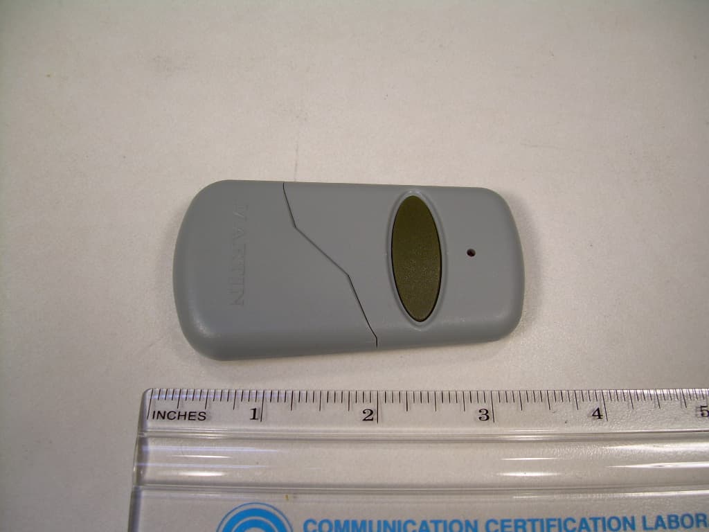
Click to zoom
Application Details
- Equipment Class
- DSC - Part 15 Security/Remote Control Transmitter
- Date of Grant
- Jun 05, 2007
- Application Purpose
- Original Equipment
- Date of Application
- Jun 05, 2007
- Equipment Note
- Martin Doors Stinger Transmitter
- Frequency Range
- 303.80000000 - 303.80000000
- Company
- Martin Doors
- Country
- United States
Documents & Files
Document Text
Text extracted from the exhibit documents filed with the FCC. Open a document above to read the original.
External Photos
Front View of the EUT Back View of the EUT
Internal Photos
View of the Component Side of the PCB View of the Trace Side of the PCB
Test Report
COMMUNICATION CERTIFICATION LABORATORY 1940 West Alexander Street Salt Lake City, UT 84119 801-972-6146 Test Report Certification Test Of: 303MAD21V FCC ID: VBC303MAD21V Test Specification: FCC PART 15, Subpart C Test Report Serial No: 590 Applicant: Martin Doors 2828 South 900 West Salt Lake City, UT 84119 Dates of Test: January 10, 2007 February 7, 2007 March 6, 2007 March 28 & 29, 2007 April 19, 2007 May 8, 2007 Issue Date: May 30, 2007 Accredited Testing Laboratory By: NVLAP Lab Code 100272-0 COMMUNICATION CERTIFICATION LABORATORY TEST REPORT: 590 FCC ID: VBC303MAD21V Page 2 of 26 CERTIFICATION OF ENGINEERING REPORT This report has been prepared by Communication Certification Laboratory to determine compliance of the device described below with the certification requirements of FCC Part 15, Subpart C. This report may be reproduced in full, partial reproduction may only be made with the written consent of the laboratory. The results in this report apply only to the sample tested. - Applicant: Martin Doors - Manufacturer: Lighting Tech Co., Ltd. - Trade Name: Stinger - Model Number: 303MAD21V - FCC ID: VBC303MAD21V On this 30 th day of May 2007, I, individually, and for Communication Certification Laboratory, certify that the statements made in this engineering report are true, complete, and correct to the best of my knowledge, and are made in good faith. Although NVLAP has accredited the Communication Certification Laboratory EMC testing facilities, this report must not be used to claim product certification, approval, or endorsement by NVLAP, NIST, or any agency of the federal government. COMMUNICATION CERTIFICATION LABORATORY Tested by: Norman P. Hansen EMC Technician COMMUNICATION CERTIFICATION LABORATORY TEST REPORT: 590 FCC ID: VBC303MAD21V Page 3 of 26 TABLE OF CONTENTS SECTION 1.0 CLIENT INFORMATION..................................4 SECTION 2.0 EQUIPMENT UNDER TEST (EUT)..........................5 SECTION 3.0 TEST SPECIFICATION, METHODS & PROCEDURES............6 SECTION 5.0 SUMMARY OF TEST RESULTS............................11 SECTION 6.0 MEASUREMENTS, EXAMINATIONS AND DERIVED RESULTS.....12 APPENDIX 1 TEST PROCEDURES AND TEST EQUIPMENT..................17 APPENDIX 2 PHOTOGRAPHS.........................................19 APPENDIX 3 MANUFACTURER’S CERTIFICATION OF EUT OPERATION.......26 COMMUNICATION CERTIFICATION LABORATORY TEST REPORT: 590 FCC ID: VBC303MAD21V Page 4 of 26 SECTION 1.0 CLIENT INFORMATION 1.1 Client Information: Company Name: Martin Doors 2828 South 900 West Salt Lake City, UT 84119 Contact Name: Scott Wall Title: Parts Department Manager 1.2 Manufacturer: Company Name: Lighting Tech Co., LTD 4F, No. 124 Hua Chen Rd. Hsing Chuang City, Taipei Hsien Taiwan, R.O.C. Contact Name: N. J. Duan Title: General Manager COMMUNICATION CERTIFICATION LABORATORY TEST REPORT: 590 FCC ID: VBC303MAD21V Page 5 of 26 SECTION 2.0 EQUIPMENT UNDER TEST (EUT) 2.1 Identification of EUT: Trade Name: Stinger Model Number: 303MAD21V Serial Number: None Options Fitted: N/A Country of Manufacture: Taiwan 2.2 Description of EUT: The Stinger 303MAD21V is a visor transmitter operating at 303.8 MHz. The 303MAD21V is designed to be used with garage door opener receivers using 303.8 MHz. The transmitter is powered by an alkaline 23A battery and has an expected life of about 12-18 months. 2.3 Modification Incorporated/Special Accessories on EUT: The following modifications were made to the 303MAD21V by the Client during testing to comply with the specification. These modifications will be implemented during manufacturing. 1. C3 was removed 2. C5 was removed 3. C6, a 2pF capacitor, was added from Transistor Q1 base to emitter. Signature: Typed Name: Scott Wall Title: Parts Department Manager COMMUNICATION CERTIFICATION LABORATORY TEST REPORT: 590 FCC ID: VBC303MAD21V Page 6 of 26 SECTION 3.0 TEST SPECIFICATION, METHODS & PROCEDURES 3.1 Test Specification: Title: FCC PART 15, Subpart C (47 CFR 15) Applicable Sections: §15.203 Antenna Requirement §15.231 Periodic operation in the band 40.66-40.70 MHz and above 70 MHz Purpose of Test: The tests were performed to demonstrate Initial compliance. 3.2 Methods & Procedures: 3.2.1 §15.203 An intentional radiator shall be designed to ensure that no antenna other than that furnished by the responsible party shall be used with the device. The use of a permanently attached antenna or of an antenna that uses a unique coupling to the intentional radiator shall be considered sufficient to comply with the provisions of this Section. The manufacturer may design the unit so that a broken antenna can be replaced by the user, but the use of a standard antenna jack or electrical connector is prohibited. This requirement does not apply to carrier current devices or to devices operated under the provisions of Sections 15.211, 15.213, 15.217, 15.219, or 15.221. Further, this requirement does not apply to intentional radiators that must be professionally installed, such as perimeter protection systems and some field disturbance sensors, or to other intentional radiators which, in accordance with Section 15.31(d), must be measured at the installation site. However, the installer shall be responsible for ensuring that the proper antenna is employed so that the limits in this Part are not exceeded. 3.2.2 §15.231 (a) The provision of this section are restricted to periodic operation within the band 40.66-40.70 MHz and above 70 MHz. Except as Shown in paragraph (e) of this section, the intentional radiator is restricted to the transmission of a control signal such as those used with alarm systems, door openers, remote switches, etc. Radio control of toys is not permitted. Continuous transmissions, such as voice or video, and data transmissions are not permitted. The prohibition against data transmissions does not preclude the use of recognition codes. Those codes are used to identify the sensor that is activated or to identify the particular component as being part of the syste…
Text truncated - open the document above for the full version.
Test Setup Photos
View of the Radiated Emission Test Setup (Vertical Alignment) View of the Radiated Emission Test Setup (Horizontal Face Alignment) View of the Radiated Emission Test Setup (Horizontal Flat Alignment)
Contact Information
Applicant
Scott Wall(Sales Manager)
Test Firm
Nemko-CCL, IncThomas Jackson
Technical Specifications
| # | Rule Parts | Frequency Range | Power Output |
|---|---|---|---|
| 1 | 15.231 | 303.8 MHz - 303.8 MHz | - |