VCWTLEXEnergy Saving Lamp
Simplex (Suzhou) Co., Ltd.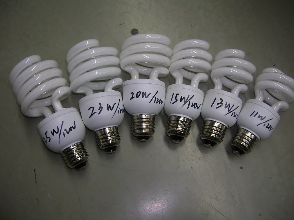
Click to zoom
Application Details
- Equipment Class
- 8CC - Part 18 Consumer Device
- Date of Grant
- Jun 06, 2007
- Application Purpose
- Original Equipment
- Date of Application
- Jun 06, 2007
- Equipment Note
- Energy Saving Lamp
- Frequency Range
- 0.45000000 - 0.47776000
- Company
- Simplex (Suzhou) Co., Ltd.
- Country
- China
Documents & Files
Document Text
Text extracted from the exhibit documents filed with the FCC. Open a document above to read the original.
Block Diagram
Block Diagram of Model: TLE-11W, TLE-13W, TLE-15W, TLE-20W, TLE-23W, TLE-25W INPUT: 120V/60Hz FUNDAMENTAL OPERATION FREQUENCY IS 0.45~30 MHz
Internal Photos
TLE-25W TLE-23W TLE-20W TLE-15W TLE-13W TLE-11W
Test Report
Report no: JSH007030392-001 Page 1 of 13 Application for FCC On Behalf of Simplex(Suzhou) Co., Ltd. Summary The equipment comply with the requirements according to the following standard(s): 47CFR Part 18 (2006): Industrial, Scientific, and Medical Equipment FCC/OET MP-5 (1986): FCC Methods of Measurements of Radio Noise Emissions From Industrial, Scientific, and Medical Equipment ANSI C63.4 (2003): Interim Standard for Methods of Measurement of Radio-Noise Emissions from Low-Voltage Electrical and Electronic Equipment in the Range of 9kHz to 40GHz. Description The appliances were tested by Intertek Testing Services ETL SEMKO Shanghai Limited and found compliance with relevant requirements described in FCC Part 18 RF lighting Device. Test results are contained in this test report and Intertek Testing Services ETL SEMKO Shanghai Limited is assumed full responsibility for the accuracy and completeness of these measurements. The test report applies to tested samples only and shall not be reproduced in part without written approval of Intertek Testing Services ETL SEMKO Shanghai Limited. Date of Test: March 13, 2007 Date of Issue: April 16, 2007 Prepared by: Report Approved by: Star Guo (Engineer) Ada Zou (Reviewer) Report no: JSH007030392-001 Page 2 of 13 Description of Test Facility Name of Firm : Intertek Testing Service Shanghai Limited Site Location : Building No.86, 1198 Qinzhou Road (North), Shanghai 200233, China Name of contact : Mr. Steve Li Phone : 86-21-64956565 ext. 271 Fax : 86-21-54262353 E-mail address : [email protected] Report no: JSH007030392-001 Page 3 of 13 CONTENTS SUMMARY................................................................................................................................................... 1 DESCRIPTION ............................................................................................................................................ 1 DESCRIPTION OF TEST FACILITY ...................................................................................................... 2 CONTENTS ............................................................................................................................................ 3 1.APPLICANT INFORMATION ............................................................................................................... 4 2.INFORMATION OF EQUIPMENT UNDER TEST (EUT) ................................................................. 4 2.1 IDENTIFICATION OF THE EUT ................................................................................................................ 4 2.2 ADDITIONAL INFORMATION ABOUT THE EUT........................................................................................ 4 2.3 PERIPHERAL EQUIPMENT....................................................................................................................... 4 3. CONDUCTED POWERLINE MEASUREMENT................................................................................ 5 3.1 CONDUCTION LIMIT FOR NON-CONSUMER RF LIGHTING DEVICE........................................................... 5 3.2 INSTRUMENTS LIST................................................................................................................................5 3.3 TEST SETUP........................................................................................................................................... 6 3.4 TEST CONFIGURATION........................................................................................................................... 6 3.5 TEST PROCEDURE.................................................................................................................................. 7 3.6 TEST RESULTS....................................................................................................................................... 8 3.7 MEASUREMENT UNCERTAINTY........................................................................................................... 13 Report no: JSH007030392-001 Page 4 of 13 1.Applicant Information Applicant : Simplex(Suzhou) Co., Ltd. Xing Pu Road, Suzhou , Jiangsu Province ,China Manufacturer 1: Simplex (Suzhou) Co.,Ltd. Xing Pu Road, Suzhou , Jiangsu Province ,China Manufacturer 2: TWIN GROWTH ELECTRONICS (SUZHOU) CO., LTD. Mudu Town , Suzhou , Jiangsu Province , China Difference between models: Different models Country of origin: P.R. China Name of contact: Mr. Shen Ying Ping Telephone: 86-512-66262625 Telefax: 86-512-66262113 2.Information of Equipment Under Test (EUT) 2.1 Identification of the EUT Equipment: Self Ballasted lamps Type of EUT: ; Production Pre-product Pro-type Type/model: TLE-11W, TLE-13W, TLE-15W, TLE-20W, TLE-23W, TLE-25W FCC ID: VCWTLEX Serial number: none Date of sample receipt 2007-03-13 Date of test 2007-03-13~2007-04-16 Rating: 120V~, 60Hz Operation frequency : none 2.2 Additional information about the EUT There are two different type of portable light for consumer use, consumer limit apply. 2.3 Peripheral equipment none Report no: JSH007030392-001 Page 5 of 13 3. Conducted Powerline Measurement 3.1 Conduction Limit for non-consumer RF lighting device Maximum RF line voltage measured with a 50uH/50 ohm LISN Frequency (MHz) (μV) dB(μV) 0.45-2.51 MHz 250 47.9 2.51-3.0 MHz 3000 69.5 3.0-30 MHz 250 47.9 RF Line Voltage dB(μV) = 20 lg RF Line Voltage (μV) 3.2 Instruments List The following instruments were used during the measurement of RF voltage conducted back into the power lines. Equipment Type Manu. Internal no. Cal. Date Due date Test Receiver ESCS 30 R&S EC 2107 2007-2-9 2008-2-8 A.M.N. ESH3-Z5 R&S EC 2109 2007-2-9 2008-2-8 Shielded room - Zhongyu EC 2838 2004-2-3 2009-2-2 Therom- Hygrograph ZJ1-2A S.M.I.F. EC 3326 2006-12-28 2007-12-27 Report no: JSH007030392-001 Page 6 of 13 3.3 Test Setup Note: means “power line” means “signal line” 3.4 Test Configuration The Conducted Powerline Measurement was proceeded in a shielded room. The EUT was connec…
Text truncated - open the document above for the full version.
Contact Information
Applicant
Ying Ping Shen(President)
Test Firm
Intertek Testing Services Limited ShanghaiJonny Jing
Technical Specifications
| # | Rule Parts | Frequency Range | Power Output |
|---|---|---|---|
| 1 | 18 | 0.45 MHz - 0.47776 MHz | - |