Click to zoom
Application Details
- Equipment Class
- DSS - Part 15 Spread Spectrum Transmitter
- Date of Grant
- Oct 15, 2007
- Application Purpose
- Original Equipment
- Date of Application
- Jul 19, 2007
- Equipment Note
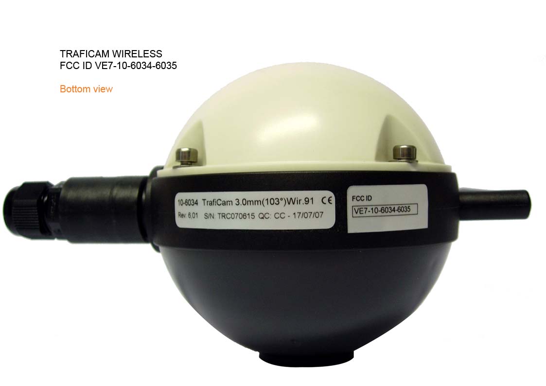
- TrafiCam Wireless US
- Frequency Range
- 902.97100000 - 926.27700000
- Company
- TRAFICON N.V.
- Country
- Belgium
Documents & Files
Select a file to view
Users Manual
Block Diagram
Cover Letter(s)
External Photos
ID Label/Location Info
Internal Photos
Operational Description
Test Report
Test Setup Photos
Contact Information
Applicant
Peter Vansteelandt(Mr)
Test Firm
Blue Guide EMC LabIvan Malfait
Technical Specifications
| # | Rule Parts | Frequency Range | Power Output |
|---|---|---|---|
| 1 | 15C | 902.971 MHz - 926.277 MHz | 220.00 mW |