VH4LW2733G USB Modem
LINKTOP TECHNOLOGY CO., LTD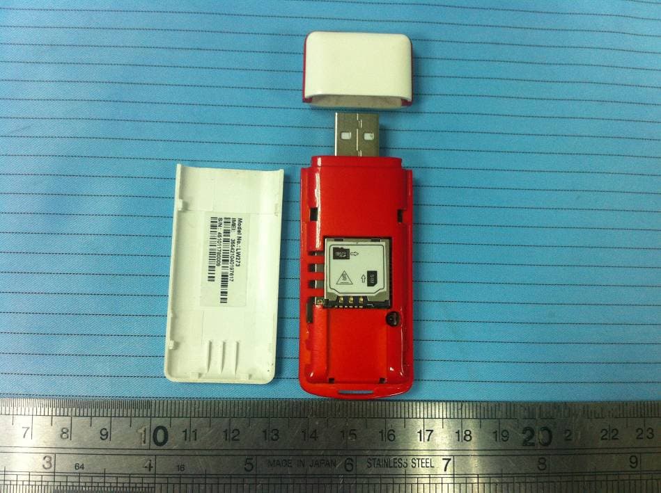
Click to zoom
Application Details
- Equipment Class
- PCB - PCS Licensed Transmitter
- Date of Grant
- Apr 11, 2012
- Application Purpose
- Original Equipment
- Date of Application
- Apr 11, 2012
- Equipment Note
- 3G USB Modem
- Frequency Range
- 1852.40000000 - 1907.60000000
- Company
- LINKTOP TECHNOLOGY CO., LTD
- Country
- China
Documents & Files
Document Text
Text extracted from the exhibit documents filed with the FCC. Open a document above to read the original.
Users Manual
1 G USB Modem MANUAL Content 1 MODEM DEVICE INTRODUCTION.............. 3 1.1 INTRODUCTION...........................................3 1.2 PRECAUTIONS............................................4 1.3 FUNCTIONS.................................................8 2 INSTALLATION PROCEDURE.................... 8 2.1 3G USB MODEM INSTALLATION 2 PROCEDURE FOR WINDOWS 2000 AND WINDOWS XP...................................................8 2.2 3G USB MODEM INSTALLATION PROCEDURE FOR WINDOWS VISTA, WINDOWS 7......................................................................12 2.3 3G USB MODEM INSTALLATION PROCEDURE FOR LINUX (UBUNTU)...............15 2.4 3G USB MODEM INSTALLATION PROCEDURE FOR MAC...................................19 3. DETAILED FEATURES DESCRIPTION OF THE GUI......................................................... 20 4. USER AREA............................................... 22 5. FAQ AND TROUBLESHOOTING.............. 32 3 1 MODEM Device Introduction 1.1 Introduction Thank you for choosing 3G USB MODEM device. To guarantee the device always in its best condition, please read this manual carefully and refer to it for general operational information. The pictures, symbols and contents in this manual are just for your reference. They might not be completely identical with your device. We operate a policy of continuous development and reserves the right to update and modify the 4 technical specifications in this document at any time without prior notice. The MODEM device is a type of multi-mode, 3G modem or card, applicable to 2G/3G networks. The interface connects most PCs to the internet, integrating functions of the MODEM device and mobile phone, into a mobile communication device. Via 2G/3G mobile networks, it supports data services and SMS services, helping you break away from the limitations of time and zone, and communicate wirelessly anytime and anywhere. 1.2 Precautions To the owner - When we use the product a safe distance away from the human body should be greater than or equal to 0.5cm. 5 - Some electronic devices are susceptible to electromagnetic interference sent by the MODEM device if inadequately shielded, such as electronic systems of vehicles. Please consult the device manufacturer before using MODEM device if necessary. - Operation of your PC and MODEM device may interfere with medical devices like hearing aids and pacemakers. Please always keep MODEM device more than 20 centimeters away from such medical devices when they are in use. Pull out the MODEM device if necessary. Consult a physician or the manufacturer of the medical device before using MODEM device. - Be aware of the usage limitation when using a MODEM device at places such as petrol stations or chemical factories, where there may be 6 explosive gases or explosive products being processed. Do not use MODEM device if unsure. - Store the MODEM device out of the reach of small children; it may cause injury if used as a toy. Device - Please use original accessories only or those that are authorized by the manufacturer. Using any unauthorized accessories may affect your device's performance, and violate related national regulations regarding telecom terminals. - Avoid using the MODEM device near metallic structures, devices or establishments that can emit electromagnet waves. This may adversely affect signal reception. - The MODEM device is not waterproof. Please keep it dry and store in shady and cool place. 7 - Do not use the MODEM device immediately after sudden temperature change. In such case, condensation may form inside the device, potentially causing irreversible damage to it. Please allow adequate time to dry. - Treat the MODEM device carefully and avoid destructive damage. Do not drop, twist, strike or otherwise harshly treat it. - Only a qualified maintenance agent should be permitted to undertake repair work. Please refer to your operator user guide to find the relevant contact information. - Close GUI software before you remove the device from PC/laptop. In Aircraft - Please power off the MODEM device before take-off. In order to protect in-flight 8 communication systems from interference, do not use the MODEM device in flight. Use before take off is subject to the usual aviation laws and the particular airline’s policy. If in doubt seek advice from the cabin crew. 1.3 Functions Functional support includes: Data service,Device Setting,SMS,Phonebook,etc. 2 Installation Procedure 2.1 3G USB MODEM Installation Procedure for Windows 2000 and Windows XP 1. Insert SIM card into USB Modem, then insert USB Modem into computer through USB port, the computer can find the hardware automatically and will display CD-ROM window as below picture. 9 10 11 2. If modem not installed automatically ,then go to My computer and click on 3G Modem ICON, then modem will install automatically. 3. After finishing installing,it will display the “GUI” window Remarks: If you don’t insert the SIM card into USB modem or insert incorrectly, the “Security” button, “Network” button, “Message” button and “Call’ button in “Setting” user interface will be in grey color (means unavailable) and the left top side will show “NO (U)SIM”. 4. After finishing installation, the user can change the APN to suitable for 3G Network. Please click “Setting” button from “GUI 12 window”, then click “Profile”, it will display “profile” window, then you can change, delete or add APN from here. After modifying, please select correct APN to Set Default. 2.2 3G USB MODEM Installation Procedure for Windows Vista, Windows 7 1. Insert SIM card into USB Modem, then insert USB Modem into computer through USB port, the computer can find the hardware automatically and will display “AutoPlay” window as below picture. 13 14 2. After clicking “Run Setup.exe”,computer will display the “Warning” windows to confirm to install software, please click “YES”, then it will display the “Installation” window. 3. After finishing installing,it will display the “GUI” window…
Text truncated - open the document above for the full version.
External Photos
EXHIBIT B - EUT EXTERNAL PHOTOGRAPHS EUT – Front View EUT – Rear View EUT – Open View EUT – SIM Card Board off View
ID Label/Location Info
EXHIBIT A - FCC ID LABELING AND LOCATION FCC ID Labeling Proposed FCC ID Location The label shown shall be permanently affixed at a conspicuous location on the device and be readily visible to the user at the time purchase (Labeling requirements per 2.925) Label here
Internal Photos
EXHIBIT C - EUT INTERNAL PHOTOGRAPHS EUT – Cover off View EUT – Main Board Top View Antenna EUT – Main Board Top Shielding off View EUT – Main Board Bottom View EUT – RF Board Top View EUT – RF Board Top Shielding off View EUT – RF Board Bottom View EUT – RF Board Bottom Shielding off View
RF Exposure Info
Note: This test report is prepared for the customer shown above and for the device described herein. It may not be duplicated or used in part without prior written consent from Bay Area Compliance Laboratories Corp. This report must not be used by the customer to claim product certification, approval, or endorsement by NVLAP or any agency of the Federal Government. * This report contain data that are not covered by the NVLAP accreditation and are marked with an asterisk “★" (Rev.2) SAR EVALUATION REPORT For Linktop Technology Co., LTD 2F Guangye Building, Torch Hi-Tech, Xiamen, Fujian, China FCC ID: VH4LW273 Report Type: Original Report Product Type: 3G USB Modem Test Engineer: Sandy Wang Report Number: RSZ120208001-20 Report Date: 2012-04-07 Reviewed By: Alvin Huang EMC Engineer Test Laboratory: Bay Area Compliance Laboratories Corp. (Shenzhen) 6/F, the 3rd Phase of WanLi Industrial Building, ShiHua Road, FuTian Free Trade Zone Shenzhen, Guangdong, China Tel: +86-755-33320018 Fax: +86-755-33320008 www.baclcorp.com.cn Bay Area Compliance Laboratories Corp.(Shenzhen) Report No:RSZ120208001-20 SAR Evaluation Report 2 of 105 Attestation of Test Results Company Name Linktop Technology Co., LTD EUT Description 3G USB Modem FCC ID VH4LW273 Model Number LW273 EUT Information Test Date 2012.04.01—2012.04.03 Frequency Max. SAR Level(s) Measured Limit(W/Kg) GSM 850 0.636 W/kg 1g Body Tissue PCS 1900 0.782 W/kg 1g Body Tissue WCDMA 850 0.606 W/kg 1g Body Tissue WCDMA 1900 0.976 W/kg 1g Body Tissue 1. 6 ANSI / IEEE C95.1 : 2005 IEEE Standard for Safety Levels with Respect to Human Exposure to Radio Frequency Electromagnetic Fileds,3 kHz to 300 GHz. ANSI / IEEE C95.3 : 2002 IEEE Recommended Practice for Measurements and Computations of Radio Frequency Electromagnetic Fields With Respect to Human Exposure to SuchFields,100 kHz—300 GHz. OET BULLETIN 65 SUPPLEMENT C Evaluating Compliance with FCC Guidelines for Human Exposure To Radiofrequency Electromagnetic Fields Applicable Standards IEEE1528:2003 IEEE Recommended Practice for Determining the Peak Spatial-Average Specific Absorption Rate (SAR) in the Human Head from Wireless Communications Devices: Measurement Techniques Note: This wireless device has been shown to be capable of compliance for localized specific absorption rate (SAR) for General Population/Uncontrolled Exposure limits specified in ANSI/IEEE Standards and has been tested in accordance with the measurement procedures specified in FCC OET 65 Supplement C and IEEE 1528-2003. The results and statements contained in this report pertain only to the device(s) evaluated. Bay Area Compliance Laboratories Corp.(Shenzhen) Report No:RSZ120208001-20 SAR Evaluation Report 3 of 105 TABLE OF CONTENTS DOCUMENT REVISION HISTORY ............................................................................................................................ 4 EUT DESCRIPTION........................................................................................................................................................ 5 TECHNICAL SPECIFICATION............................................................................................................................................. 5 REFERENCE, STANDARDS, AND GUILDELINES ................................................................................................. 6 SAR LIMITS..................................................................................................................................................................... 7 FACILITIES AND ACCREDITATION ........................................................................................................................ 8 DESCRIPTION OF TEST SYSTEM ............................................................................................................................. 9 EQUIPMENT LIST AND CALIBRATION ................................................................................................................16 EQUIPMENTS LIST & CALIBRATION INFORMATION......................................................................................................16 SAR MEASUREMENT SYSTEM VERIFICATION ................................................................................................17 LIQUID VERIFICATION...................................................................................................................................................17 SYSTEM ACCURACY VERIFICATION..............................................................................................................................19 SAR SYSTEM VALIDATION DATA........................................................................................................................20 EUT TEST STRATEGY AND METHODOLOGY....................................................................................................24 TEST POSITIONS FOR DEVICE OPERATING NEXT TO A PERSON’S EAR.........................................................................24 CHEEK/TOUCH POSITION..............................................................................................................................................25 EAR/TILT POSITION.......................................................................................................................................................25 TEST POSITIONS FOR BODY-WORN AND OTHER CONFIGURATIONS................................................................................26 SAR EVALUATION PROCEDURE....................................................................................................................................27 CONDUCTED OUTPUT POWER MEASUREMENT .............................................................................................28 PROVISION APPLICABLE................................................................................................................................................28 TEST PROCEDURE...................................…
Text truncated - open the document above for the full version.
Test Report
EXHIBIT D - TEST SETUP PHOTOGRAPHS Radiated Emissions – Front View (Below 1 GHz) Radiated Emissions – Rear View (Below 1 GHz) Radiated Emissions – Front View (Above 1 GHz) Radiated Emissions – Rear View (Above 1 GHz) Frequency Stability Test View
Test Setup Photos
EXHIBIT D - TEST SETUP PHOTOGRAPHS Radiated Emissions – Front View (Below 1 GHz) Radiated Emissions – Rear View (Below 1 GHz) Radiated Emissions – Front View (Above 1 GHz) Radiated Emissions – Rear View (Above 1 GHz) Frequency Stability Test View
Contact Information
Applicant
Jianhua Lv Lv
Test Firm
Bay Area Compliance Laboratory Corp. (Shenzhen)John Chan
Technical Specifications
| # | Rule Parts | Frequency Range | Power Output | Emission | Tolerance |
|---|---|---|---|---|---|
| 6 | 24E | 1.85 GHz - 1.91 GHz | 113.00 mW | 4M83F9W | 2.5 ppm |