Internal Photos of EUT ---------------------------------------------------------------- 9/14 Applicant: ASUSTeK Computer Inc. FCC ID: MSQWL130N Training Research Co., Ltd., TEL: 886-2-26935155, Fax: 886-2-26934440 Internal Photos of EUT ---------------------------------------------------------------- 10/14 Applicant: ASUSTeK Computer Inc. FCC ID: MSQWL130N Training Research Co., Ltd., TEL: 886-2-26935155, Fax: 886-2-26934440 Internal Photos of EUT ---------------------------------------------------------------- 11/14 Applicant: ASUSTeK Computer Inc. FCC ID: MSQWL130N Training Research Co., Ltd., TEL: 886-2-26935155, Fax: 886-2-26934440 Internal Photos of EUT ---------------------------------------------------------------- 12/14 Applicant: ASUSTeK Computer Inc. FCC ID: MSQWL130N Training Research Co., Ltd., TEL: 886-2-26935155, Fax: 886-2-26934440 Internal Photos of EUT ---------------------------------------------------------------- 13/14 Applicant: ASUSTeK Computer Inc. FCC ID: MSQWL130N Training Research Co., Ltd., TEL: 886-2-26935155, Fax: 886-2-26934440 Internal Photos of EUT ---------------------------------------------------------------- 14/14 Applicant: ASUSTeK Computer Inc. FCC ID: MSQWL130N Training Research Co., Ltd., TEL: 886-2-26935155, Fax: 886-2-26934440
Measurement of Maximum Permissible Exposure ---------------------------------------- 1/3 Applicant: ASUSTeK Computer Inc. FCC ID: MSQWL130N Training Research Co., Ltd., TEL: 886-2-26935155, Fax: 886-2-26934440 Measurement of Maximum Permissible Exposure 1. Foreword In adopt with the Human Exposure IEEE C95.1, and according to the FCC 1.1310. The Maximum Permissible Exposure (MPE) is obligated to measure in order to prove the safety of radiation harmfulness to the human body. The Gain of the antenna used is measured in an Anechoic chamber. The maximum total power to the antenna is to be recorded. By adopting the Friis Transmission Formula and the power gain of the antenna, we can find the distance right away from the product, where the limit of the MPE is. 2. Description of EUT FCC ID : MSQWL130N Product name : Super Speed N Wireless PCI Adapter Model : WL-130N Classification : Mobile Device (i) Under normal use condition, the antenna is at least 20cm away from the user; (ii) Warning statement for keeping 20cm separation distance and the prohibition of operating next to the person has been printed in the user’s manual Frequency Range : IEEE 802.11b/g/n Draft 1.0 20M: 2.412GHz ~ 2.462GHz IEEE 802.11n Draft 1.0 40M: 2.422GHz ~ 2.452GHz Supported Channel : IEEE 802.11b/g/n Draft 1.0 20M: 11 Channels IEEE 802.11n Draft 1.0 40M: 7 Channels Modulation Skill : DBPSK, DQPSK, CCK, OFDM Power Type : Powered by Protocol Control Information Interface of PC Measurement of Maximum Permissible Exposure ---------------------------------------- 2/3 Applicant: ASUSTeK Computer Inc. FCC ID: MSQWL130N Training Research Co., Ltd., TEL: 886-2-26935155, Fax: 886-2-26934440 3. Limits for Maximum Permissible Exposure (MPE) Frequency Range (MHz) Electric Field Strength (V/m) Magnetic Filed Strength (H) (A/m) Power Density (S) (mW/cm2) Averaging Time |E| 2 , |H| 2 or S (minutes) (A) Limits for Occupational/Controlled Exposure 0.3-3.0 614 1.63 100 6 3.0-30 1842/f 4.89/f 900/f 2 6 30-300 61.4 0....
| # | Rule Parts | Frequency Range | Power Output |
|---|---|---|---|
| 1 | 15C | 2.40 GHz - 2.48 GHz | 2.00 mW |
Test Report ---------------------------------------------------------------------------------- 1/82 Report No.: A5415060979, FCC Part 15.247 Training Research Co., Ltd., TEL: 886-2-26935155, Fax: 886-2-26934440 MEASUREMENT REPORT of Super Speed N Wireless PCI Adapter Applicant : ASUSTek Computer Inc. EUT : Super Speed N Wireless PCI Adapter Model No. : WL-130N FCC ID : MSQWL130N Tested by : Training Research Co., Ltd. TEL : 886-2-26935155 FAX : 886-2-26934440 No. 255, Nanyang Street, Shijr, Taipei Hsien 221, Taiwan, R.O.C. Test Report ---------------------------------------------------------------------------------- 2/82 Report No.: A5415060979, FCC Part 15.247 Training Research Co., Ltd., TEL: 886-2-26935155, Fax: 886-2-26934440 CERTIFICATION We here by verify that: The test data, data evaluation, test procedures and equipment configurations shown in this report were made mainly in accordance with the procedures given in ANSI C63.4 (2003) as a reference. All test were conducted by Training Research Co., Ltd., 255 Nanyang Street, Shijr, Taipei Hsien 221, Taiwan, R.O.C. Also, we attest to the accuracy of each. We further submit that the energy emitted by the sample EUT tested as described in the report is in compliance with the technical requirements set forth in the FCC Rules Part 15 Subpart C Section 15.247. Applicant : ASUSTek Computer Inc. Applicant Address : 4F, No. 150, Li-Te Rd., Peitou, Taipei, Taiwan, R.O.C. Product Name : Wireless Local Area Network Adapter Model : WL-130N Report No. : A5415060979 Test Date : November 20, 2006 ~ November 30, 2006 Prepared by: Approved by: Jack Tsai Frank Tsai Conditions of issue : (1) This test report shall not be reproduced except in full, without written approval of TRC. And the test result contained within this report only relate to the sample submitted for testing. (2) This report must not be used by the client to claim product endorsement by NVLAP or any agency of U.S. Government. (3) This test report, measurements mad...
Test Setup Photos ------------------------------------------------------------------------ 1/2 Applicant: ASUSTeK Computer Inc. FCC ID: MSQWL130N Training Research Co., Ltd., TEL: 886-2-26935155, Fax: 886-2-26934440 Conducted Test Setup Placement: Front View of the Test Configuration Side View of the Test Configuration Test Setup Photos ------------------------------------------------------------------------ 2/2 Applicant: ASUSTeK Computer Inc. FCC ID: MSQWL130N Training Research Co., Ltd., TEL: 886-2-26935155, Fax: 886-2-26934440 Radiated Test Setup Placement: Front View of the Test Configuration Rear View of the Test Configuration
User Manual Super Speed N Wireless PCI Adapter WL-130N ( For 802.11n draft, 802.11g & 802.11b Networks ) ® E3123/ March 2007 R 2ASUS WLAN Adapter No part of this manual, including the products and software described in it, may be reproduced, transmitted, transcribed, stored in a retrieval system, or translated into any language in any form or by any means, except documentation kept by the purchaser for backup purposes, without the express written permission of ASUSTeK COMPUTER INC. (“ASUS”). ASUS PROVIDES THIS MANUAL “AS IS” WITHOUT WARRANTY OF ANY KIND, EITHER EXPRESS OR IMPLIED, INCLUDING BUT NOT LIMITED TO THE IMPLIED WARRANTIES OR CONDITIONS OF MERCHANTABILITY OR FITNESS FOR A PARTICULAR PURPOSE. IN NO EVENT SHALL ASUS, ITS DIRECTORS, OFFICERS, EMPLOYEES OR AGENTS BE LIABLE FOR ANY INDIRECT, SPECIAL, INCIDENTAL, OR CONSEQUENTIAL DAMAGES (INCLUDING DAMAGES FOR LOSS OF PROFITS, LOSS OF BUSINESS, LOSS OF USE OR DATA, INTERRUPTION OF BUSINESS AND THE LIKE), EVEN IF ASUS HAS BEEN ADVISED OF THE POSSIBILITY OF SUCH DAMAGES ARISING FROM ANY DEFECT OR ERROR IN THIS MANUAL OR PRODUCT. Product warranty or service will not be extended if: (1) the product is repaired, PRGLÀHGRUDOWHUHGXQOHVVVXFKUHSDLUPRGLÀFDWLRQRIDOWHUDWLRQLVDXWKRUL]HG in writing by ASUS; or (2) the serial number of the product is defaced or missing. Products and corporate names appearing in this manual may or may not be registered trademarks or copyrights of their respective companies, and are XVHGRQO\IRULGHQWLÀFDWLRQRUH[SODQDWLRQDQGWRWKHRZQHUVҋEHQHÀWZLWKRXW intent to infringe. SPECIFICATIONS AND INFORMATION CONTAINED IN THIS MANUAL ARE FURNISHED FOR INFORMATIONAL USE ONLY, AND ARE SUBJECT TO CHANGE AT ANY TIME WITHOUT NOTICE, AND SHOULD NOT BE CONSTRUED AS A COMMITMENT BY ASUS. ASUS ASSUMES NO RESPONSIBILITY OR LIABILITY FOR ANY ERRORS OR INACCURACIES THAT MAY APPEAR IN THIS MANUAL, INCLUDING THE PRODUCTS AND SOFTWARE DESCRIBED IN IT. Copyright © 2007 ASUSTeK COMPUTER INC. All Rig...
1 2 34 ABCD 4 3 2 1 D CBA WAV-503TX TransmitterAirwave Video&Audio Wireless Module ANTENNA MD7121 Receiver2.4G Wireless Module BOX ANT A-R Video Audio L Audio R A-L Video WT6561F4In1 Controller MCU(Receiver) 4In1 Cable I/O Power Power I/O Power ANTENNA Indicator SwitchChannle Select Link LEDPower LED Module 2-1 Module 1-1 WAV-503RX ReceiverAirwave Video&Audio Wireless Module Module 1-2 ANT ANTENNA SwitchChannle Select Video Audio L Audio R Power GVD410 BDMMicro Display Power Control Keys I/O Contrast AdjustBright Adjust UTC3544Amplifier I/O Power Sound OutputHeadphone I/O RheostatVolume Adjust Part No. Prepared By Date Approved By Qi Yong 2006-10-08 File No. WF-PIE-042/A FRONT ELECTRONIC CO., LTD. TITLE Rev: A02Model No. Block Diagram For Trimersion MD7121 Transmitter2.4G Wireless Module ANTENNA SN8P1707Q4In1 Controller MCU(Transmitter) Module 2-2 Power NTSC&PAL Power Indicator Link LEDTrack LEDPower LED MG1101Gyroscope I/O I/O I/O I/OI/O I/O I/O I/O I/O I/O Video Audio L Audio R Four Plug To Different Console Power I/O 4In1 Controller I/O I/O I/O XC6368BPower Manager Power Power BatterySize:AA 1.5V X 4 Power GUN HELMET I/OI/O SwitchTrack Switch I/O *The Product Includes a Cable That Convert PC Audio To BNC. Composite Video Input *External VGA To NTSC/PAL Converter 4In1 Platform Contain: PS2 、 XBOX 、 GC & PC *Platform: Auto Switch PS2(Gamepad)XBOX(Gamepad)GC(Gamepad)PC(Mouse+Keyboard) Replace Right Stick Or Mouse Move
Spectrum Research & Testing Lab., Inc. No. 101-10, Ling 8, Shan-Tong Li, Chung-Li City, Taoyuan, Taiwan, R.O.C. Photo Page: 1 of 8 PHOTOS OF EUT
Spectrum Research & Testing Lab., Inc. No. 101-10, Ling 8, Shan-Tong Li, Chung-Li City, Taoyuan, Taiwan, R.O.C. Sample of FCC ID Label The device is large enough for it to be placed warning statement on the device as follow: FCC ID: UBQTR101X This device complies with Part 15 FCC Rules. Operation is subject to the following two conditions: (1) This device may not cause harmful interference, and (2) This device must accept any interference received, including interference that may cause undesired operation.
Spectrum Research & Testing Lab., Inc. No. 101-10, Ling 8, Shan-Tong Li, Chung-Li City, Taoyuan, Taiwan, R.O.C. Photo Page: 2 of 8 PHOTOS OF EUT- Top-Inside Spectrum Research & Testing Lab., Inc. No. 101-10, Ling 8, Shan-Tong Li, Chung-Li City, Taoyuan, Taiwan, R.O.C. Photo Page: 3 of 8 PHOTOS OF EUT-All Parts of Controlller Spectrum Research & Testing Lab., Inc. No. 101-10, Ling 8, Shan-Tong Li, Chung-Li City, Taoyuan, Taiwan, R.O.C. Photo Page: 4 of 8 PHOTOS OF EUT-Controller 1 Spectrum Research & Testing Lab., Inc. No. 101-10, Ling 8, Shan-Tong Li, Chung-Li City, Taoyuan, Taiwan, R.O.C. Photo Page: 5 of 8 PHOTOS OF EUT-Controller 2 Spectrum Research & Testing Lab., Inc. No. 101-10, Ling 8, Shan-Tong Li, Chung-Li City, Taoyuan, Taiwan, R.O.C. Photo Page: 6 of 8 PHOTOS OF EUT-Controller MCU Board Spectrum Research & Testing Lab., Inc. No. 101-10, Ling 8, Shan-Tong Li, Chung-Li City, Taoyuan, Taiwan, R.O.C. Photo Page: 7 of 8 PHOTOS OF EUT-Electrical Parts Spectrum Research & Testing Lab., Inc. No. 101-10, Ling 8, Shan-Tong Li, Chung-Li City, Taoyuan, Taiwan, R.O.C. Photo Page: 8 of 8 PHOTOS OF EUT-Switches of Controller
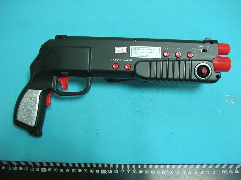
FCC ID: UBQTR101X Operational Description of the equipment Turn the POWER SWITCH on the GUN CONTROLLER to “ON”. To verify correct operation of the GUN CONTROLLER, open a program like “Notepad” and push buttons on the gun, you will see characters typed across the screen. Start the First Person Shooter (FPS) game. The default GUN CONTROLLER macro is preset to a “QUAKE” configuration. If you need a different configuration you have two options: 1. Change the preset macros by following the MACRO ASSIGNMENT INSTRUCTIONS. 2. Open the keyboard binding menu in the software configuration menu of your FPS game and manually program each button. The Mouse Look function of the FPS game should function with the movement of the HMD the same way it does by using a mouse. The TRIMERSION will not interrupt the mouse or keyboard functionality but will work in combination with it. PRODUCT Wireless Gun Controller Trimersion MODEL NO. TR101X POWER REQUIREMENTS DC 6V, ≦160mA FREQUENCY BAND 2400 ~ 2483MHz CARRIER FREQUENCY CH0:2404~CH3:2478 MHz CHANNEL SPACING 24.6 MHz RF OUTPUT POWER -5dBm MODULATION TYPE FSK DUTY CYCLE 2% NUMBER OF CHANNEL 4 BIT RATE OF TRANSMISSION 1 Mbps MODE OF OPERATION duplex ANTENNA TYPE PCB Antenna
1 2 3 4 56 ABCD 6 5 4 3 2 1 D CBA C222P C122P R510M C7 104 C12 4.7UF C6 104 C9 10uF C1010P C1110P R284.7R C8 104 +5V VDD C3104 R3215K R3115K C131u VDD R73.6K R83.6K R93K TXD CLK DSR DATA/DTR RXD C18 3.3u/16V PD7 PD6 PA4 VDD DATA/DTR R2715K R2615K Y1 6MHz D+D- Q28050 R1330 FP_RDY R6 0 L115uH R2 22 R3 22 PD1 PD2 PD3 PD4 PD5 PA1 DATA/DTR PC1PC2 CD_TXEN TRXD F_CLK LED1 C17104 + C21 100u/16v R3020K VDD PD6 Lx 3 GND 1 Vout 2 U37805 +8V C20 47uF/16V D3IN5819 +5V 1234567 CN1 PS2 DSRCLKTXD VBI RXD +8V PE0 R4150K PA2PA3PA5 VDD V33 1 DP0 2 DM0 3 DP1 4 DM1 5 DP2 6 DM2 7 VDD 8 VSS 9 PB0 10 PB1 11 PB2 12 PB3 13 PB4 14 PB5 15 PB6 16 PB7 17 PD0 18 PD1 19 PD2 20 PD3 21 PD4 22 PD5 23 PD6 24 PD7 25 PA0 26 PA1 27 PA2 28 PA3 29 PA4 30 PA5 31 PA6 32 PA7 33 PC0 34 PC1 35 PC2 36 PC3 37 PC4 38 PC5 39 PC6 40 PC7 41 VDD 42 XTAL1 43 XTAL2 44 VSS 45 RESET 46 PE0 47 PE1 48 U1 WT6561TF QFP PC7 PE0 VBI PA6 R2920K PD7 SPI_CS SPI_CLK SPI_RXD SPI_TXD SPI_CSSPI_CLKSPI_TXDSPI_RXDCD_TXENTRXDF_CLKFP_RDY PD0 + C14 22u/10v C19 47uF/16V C16104 C15 104 12345 CN2 USB/XBOX RF_VDD R10 2K R11 2K R12 2K R13 2K R14 2K R15 2K R16 2K R17 2K R1812K R1912K R2012K R2112K R2212K R2312K R2412K R2512K S 1 C 2 D 3 Q 4 GND 5 67 VDD 8 93C46 PA4PA3 PA1 PA2 VDD R33 10K VDD 1234 8765 S1SW DIP-4 ANT1 ANTENNA A/LA/R C4 470uF/10V C5 470uF/16V VDD AV SPI_CS 1 SPI_CLK 2 SPI_RXD 3 SPI_TXD 4 CD_TXEN 5 TRXD 6 F_CLK 7 VIN 11 GND 9 FP_RDY 8 GND 10 CLK 12 CN3MD7121 Part No. Prepared By Date Approved By Qi Yong 2006-10-23 File No. WF-PIE- 042/A FRONT ELECTRONIC CO., LTD. TITLE Rev: A01Model No. Circuit Diagram For Box Of Trimersion D2 IN5819 D1IN5819 DATA/DTR DP0DM0 ANT Vin 2 GND 1 Vout 3 U4RC62FP-2502PR 1234 CN4NGC PROGRAM POINT 19 Q3 S9018 R35 10K R37 6.8K + C22 4.7uF/10V R39 1K VIDEO_OUT VIDEO_OUT C24 470P R3475 V-in VDD 1 2 3 4 5 6 J1AV-IN V-in A/R A/L 1 2 3 4 5 6 J2AV-OUT VIDEO_OUT A/R A/L Q4 S9018 R36 10K R38 6.8K + C23 4.7uF/10V R40 1K C25 470P V-in VDD Airwave Video&Audio Wireless Module Q18550 GND 1 V-IN 2 GND 3 L-IN 4 GND 5 R-IN ...
Spectrum Research & Testing Lab., Inc. No. 101-10, Ling 8, Shan-Tong Li, Chung-Li City, Taoyuan, Taiwan, R.O.C. TEST REPORT Reference No.:A07032001 Report No.:FCCA07032001-01 FCC ID: UBQTR101X Page:2 of 34 Date: APR. 12, 2007 Table of Contents 1. DOCUMENT POLICY AND TEST STATEMENT ................................................ 4 1.1 DOCUMENT POLICY ........................................................................................ 4 1.2 TEST STATEMENT ............................................................................................ 4 1.3 EUT MODIFICATION ......................................................................................... 4 2. DESCRIPTION OF EUT AND TEST MODE....................................................... 5 2.1 GENERAL DESCRIPTION OF EUT................................................................... 5 2.2 DESCRIPTION OF SUPPORT UNIT ................................................................. 5 2.3 DESCRIPTION OF TEST MODE ....................................................................... 5 3. DESCRIPTION OF APPLIED STANDARDS ...................................................... 6 4. RADIATED EMISSION TEST ............................................................................. 7 4.1 RADIATED EMISSION LIMIT............................................................................. 7 4.2 TEST EQUIPMENT............................................................................................ 8 4.3 TEST SET-UP(30MHZ - 1GHZ) ......................................................................... 9 4.4 TEST SET- UP (1GHZ - 25GHZ).......................................................................10 4.5 TEST PROCEDURE .........................................................................................11 4.6 EUT OPERATING CONDITION ........................................................................11 4.7 RADIATED EMISSION TEST RESULT ..........................................................