Click to zoom
Application Details
- Equipment Class
- DSS - Part 15 Spread Spectrum Transmitter
- Date of Grant
- Aug 29, 2007
- Application Purpose
- Original Equipment
- Date of Application
- Aug 29, 2007
- Equipment Note
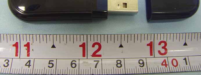
- BLUETOOTH DONGLE
- Frequency Range
- 2402.00000000 - 2480.00000000
- Company
- Liyuh Technology Ltd.
- Country
- Taiwan
Documents & Files
Select a file to view
Users Manual
Cover Letter(s)
External Photos
ID Label/Location Info
Internal Photos
RF Exposure Info
Test Report
Test Setup Photos
Contact Information
Applicant
Evan Zen(Manager/R&D Department)
Test Firm
Sporton International IncKathy Lin
Technical Specifications
| # | Rule Parts | Frequency Range | Power Output |
|---|---|---|---|
| 1 | 15C | 2.40 GHz - 2.48 GHz | 18.00 mW |