VIK-OH001Transmitter module for use in medical and dental wireless remote control devices
Zila Inc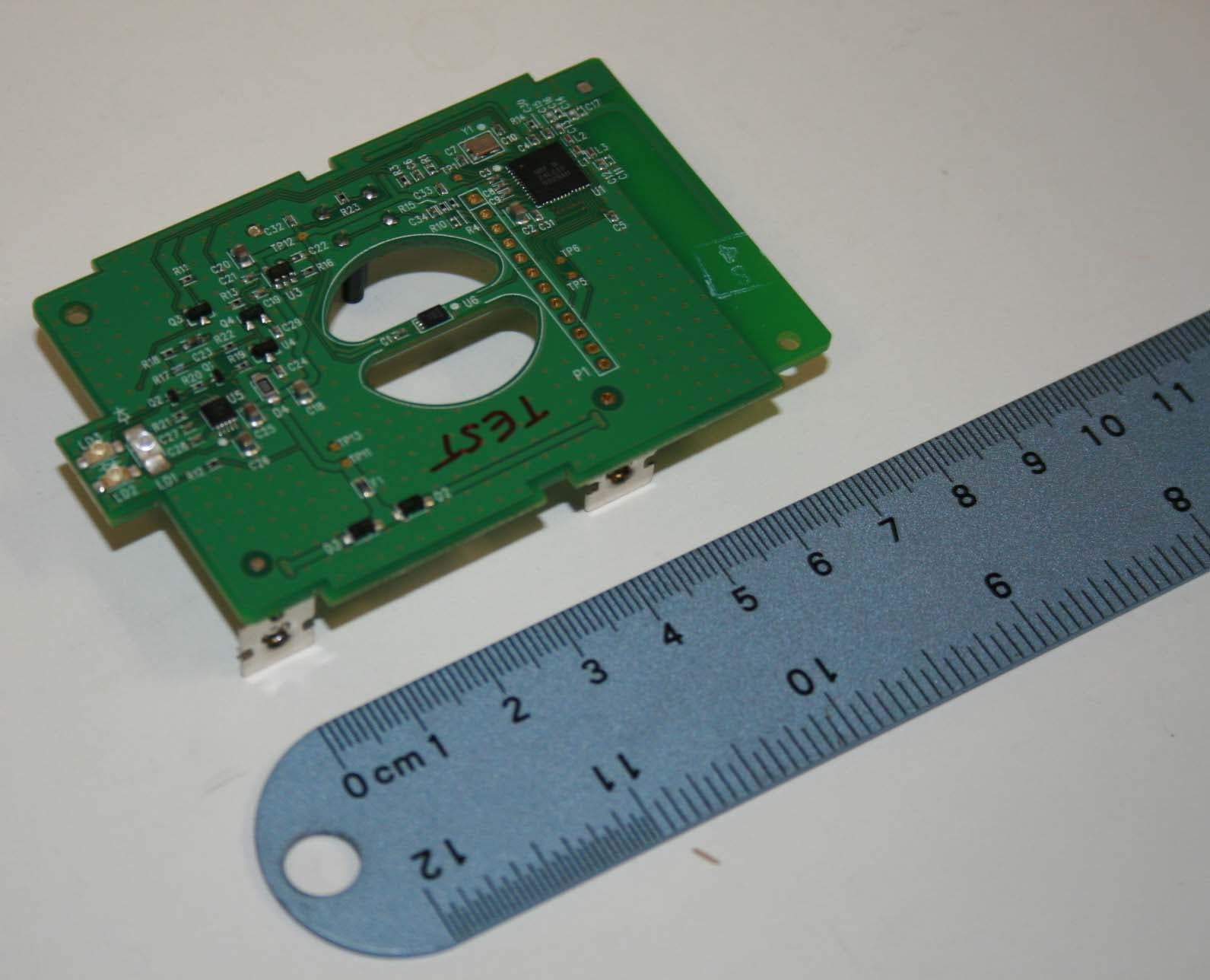
Click to zoom
Application Details
- Equipment Class
- DXX - Part 15 Low Power Communication Device Transmitter
- Date of Grant
- May 18, 2010
- Application Purpose
- Original Equipment
- Date of Application
- May 12, 2010
- Equipment Note
- Transmitter module for use in medical and dental wireless remote control devices
- Frequency Range
- 2405.00000000 - 2478.00000000
- Company
- Zila Inc
- Country
- United States
Documents & Files
Document Text
Text extracted from the exhibit documents filed with the FCC. Open a document above to read the original.
Users Manual
8550 Higuera Street Culver City, CA 90232 (310) 845-8200 phone (310) 845 1500 fax discusdental.com USER’S MANUAL AND INTALLATION GUIDE FOR DISCUS TRANSMITTER MODULE 04-1293P03 8550 Higuera Street Culver City, CA 90232 (310) 845-8200 phone (310) 845 1500 fax discusdental.com I. DESCRIPTION Discus Dental 04-1293P03 Transmitter Module is a radio frequency transmitting device intended for integration into professional products requiring a wireless link. This module does not contain the receiver necessary to complete the wireless link. The module also includes a Hall sensor which measures magnetic fields. This feature allows the use of low cost permanent magnets for measuring small change in distance, such as the ones used in foot pedal or foot switch applications. Magnetic field strength data is sent through the wireless link to the receiver. II. MODULE SPECIFICATIONS AND REQUIREMENTS a. Mechanical Specifications All 3 indicators are Product ID label The RF circuit including located on the is located on this the PCB trace antenna opposite side of the surface in the area is located in this area on board in this area shown. both sides of the board. Keep clear for best transmission performance. 8550 Higuera Street Culver City, CA 90232 (310) 845-8200 phone (310) 845 1500 fax discusdental.com The ID label indicates the following information: Discus Dental, LLC Model: 04-1293P03 REV __ FCC ID: VIK-OH001 IC: 7260A-OH001 VID ____ Lot: _________ b. Electrical Specifications Operating voltage range: 3.4VDC to 4.5VDC Operating current consumption: 100mA Recommended power source: Disposable AAA Alkaline batteries (x6) Can also operate on 3 cells (one cell bank) c. Magnetic Interface Requirements: A number of combinations of magnetic strengths and applied distances could successfully work with this module. The magnetic field required is polarized, so magnet orientation is critical. Hall sensor useable voltage range: 0 to 1.2V Hall sensor voltage relationship to magnetic field: Decreasing voltage with magnetic force increase Typical magnet characteristics: Pull Force: 1.05 lbs Surface Field: 1217 Gauss Brmax: 14,800 Gauss Magnet distance range: Selected based on magnet size and force d. Environmental Specifications Operating temperature: 0ºC to +40ºC Storage temperature: -20ºC to +50ºC Relative Humidity: 10% - 95% RH non-condensing 8550 Higuera Street Culver City, CA 90232 (310) 845-8200 phone (310) 845 1500 fax discusdental.com e. RF Communications Specifications The module transmits within the 2.4GZ ISM band. The selected frequencies of operation are: Channel # Frequency [MHZ] 1 2405 2 2410 3 2415 4 2420 5 2425 6 2430 7 2435 8 2440 9 2445 10 2450 11 2455 12 2460 13 2465 14 2470 15 2475 Sync 2478 There are 15 channels of normal operation and one specially assigned channel, sync, only used for transmitter-receiver pairing purposes. During the pairing (synchronization) process, both a new channel number and a new 5- byte address are selected by the module and get communicated to the receiver. Each time it is paired with a receiver, the module increases the frequency by 2 channels, meaning 10MHZ increments. The change is always in the ascending order and wraps around once the maximum normal operating channel number (channel 15) has been exceeded. For example, if starting at channel 1, then the following are the order of channel numbers every time pairing is performed: 1, 3, 5, 7, 9, 11, 13, 15, 2, 4, 6, 8, 10, 12, 14, 1, 3, ...... 8550 Higuera Street Culver City, CA 90232 (310) 845-8200 phone (310) 845 1500 fax discusdental.com f. Indicators: There are 3 indicators on the module: 1. Amber: This light blinks when power supply voltage level drops below approximately 3.4V. Though the module is still functional at this point, it acts as a warning for the User to replace the batteries soon (if batteries are used as the source of power). 2. Green: This light indicates the unit is in fully powered and awake, but in idle mode. It is ready to transmit if the magnetic field is strong enough to qualify. 3. Blue: The blue light, when solid on, indicates normal RF packets are being transmitted. When blinking, it indicates that it is in pairing (Sync) mode. III. OPERATING INSTRUCTIONS a. Pairing With a Receiver: i. The receiver (not supplied with this module) must be put into learning mode in order to start the pairing process ii. Then, the button on this module must be pressed continuously until the blue light starts flashing. This usually takes about 3 seconds. iii. Once blue light starts flashing, release the button and the module will start a pairing mode transmission lasting about 10 seconds. The pairing mode packets contain the new wireless address and channel for the receiver to learn. b. Sleep and Wakeups: The module enters a low power sleep mode as soon as power is applied to it. The green and blue lights are off in this state. The amber light may blink if the supply voltage is low. A magnetic force applied to the Hall sensor at the center of the board wakes up the module, and RF transmission begins. A solid blue light indicates this event. c. Transmitting and Idle Modes: While transmitting, the blue LED will remain on. Once the magnetic force is no longer applied, the module enters idle mode and remains in that state for up to 2 minutes. The green light will be on during this time. If no magnetic force is sensed in this period, the module will enter low power/sleep mode and the green and blue lights will remain off. 8550 Higuera Street Culver City, CA 90232 (310) 845-8200 phone (310) 845 1500 fax discusdental.com d. Calibration: Due to variations in magnetic forces and the mechanical distance of it to the Hall sensor, calibration may be necessary in order to provide the largest possible dynamic range. The magnetic force has to be in the acceptable range in order for calibration to be possible. Calibration is intended for final product factory use, though calibrating in field is not prevented. Here are the inst…
Text truncated - open the document above for the full version.
Cover Letter(s)
Re: Request of Confidentiality for FCC ID#: VIK-OH001 Pursuant to Sections 0.457(d)(I)(ii) and 0.459 of the Commission’s Rules, the Applicant hereby requests confidential treatment of information accompanying as outlined below: Schematics, Parts List, Operating Description, Block Diagrams The above materials contain trade secrets and proprietary information not customarily released to the public. The public disclosure of these matters might be harmful to the Applicant and provide unjustified benefits to its competitors. The Applicant understands that pursuant to Rule 0.457(d)(I)(ii), disclosure of this Application and all accompanying documentation will not be made before the date of the Grant for this Application. Sincerely, Brian Zargari Senior Electrical Engineer Discus Dental, LLC. Nemko Canada Inc. 303 River Road Ottawa, Ontario, Canada K1V 1H2 8550 Higuera Street (310) 845-8200 phone discusdental.com Culver City, CA 90232 (310) 845 1500 fax
Cover Letter(s)
8550 Higuera Street Culver City, CA 90232 (310) 845-8200 phone (310) 845 1500 fax discusdental.com Feb 23, 2010 Timco Engineering 849 N.W. State Road 45 PO Box 370 Newberry, FL 32669 Attn: Director of Certification FCC ID: VIK-OH001 Request Limited Modular Authority We hereby request Limited Modular Approval based on the numbered requirements identified below as we address them to be included in our application for equipment authorization. 1. The modular transmitter must have its own RF shielding. This is intended to ensure that the module does not have to rely upon the shielding provided by the device into which it is installed in order for all modular transmitter emissions to comply with Part 15 limits. It is also intended to prevent coupling between the RF circuitry of the module and any wires or circuits in the device into which the module is installed. Such coupling may result in non-compliant operation. Our equipment meets this by having a ground plane and a power plane within its PCB layers underneath the RF components and not requiring further shielding due to meeting radiated emission levels of 15.249 and 15.209. Discus Dental maintains full control of the end product into which the module will be installed. The Module will always be contained in variations of same or similar mechanical structures that will not have any other circuitry, ever. 2. The modular transmitter must have buffered modulation/data inputs (if such inputs are provided) to ensure that the module will comply with Part 15 requirements under conditions of excessive data rates or over-modulation. Our equipment meets this by having a complete, self-contained design where there are no electrical inputs (other than power) to accommodate external devices. The only input is a magnetic one and gets sensed via the module’s Hall sensor chip. Data rates and modulations are all built in and fixed, and not dependent on the magnetic field strength. 3. The modular transmitter must have its own power supply regulation. This is intended to ensure that the module will comply with Part 15 requirements regardless of the design of the power supplying circuitry in the device into which the module is installed. Our equipment meets this by having on-board 3V regulator, which further gets regulated internally by the Nordic nRF24LE1 radio chip. Therefore, power supply voltage variations do not affect transmission power levels or modulation levels. 8550 Higuera Street Culver City, CA 90232 (310) 845-8200 phone (310) 845 1500 fax discusdental.com 4. The modular transmitter must comply with the antenna requirements of Section 15.203 and 15.204(c). The antenna must either be permanently attached or employ a “unique” antenna coupler (at all connections between the module and the antenna, including the cable). Any antenna used with the module must be approved with the module, either at the time of initial authorization or through a Class II permissive change. The “professional installation” provision of Section 15.203 may not be applied to modules. Our equipment meets this by having a fixed PCB trace antenna. Antenna is not detachable and is part of the module. The module is a single-board design. 5. The modular transmitter must be tested in a stand-alone configuration, i.e., the module must not be inside another device during testing. This is intended to demonstrate that the module is capable of complying with Part 15 emission limits regardless of the device into which it is eventually installed. Unless the transmitter module will be battery powered, it must comply with the AC line conducted requirements found in Section 15.207. AC or DC power lines and data input/output lines connected to the module must not contain ferrites, unless they will be marketed with the module (see Section 15.27(a)). The length of these lines shall be length typical of actual use or, if that length is unknown, at least 10 centimeters to insure that there is no coupling between the case of the module and supporting equipment. Any accessories, peripherals, or support equipment connected to the module during testing shall be unmodified or commercially available (see Section 15.31(i)). Our equipment meets this when testing the module by itself. The module is a battery operated device and has battery terminals build into it. No housings are used during testing. 6. The modular transmitter must be labeled with its own FCC ID number, and, if the FCC ID is not visible when the module is installed inside another device, then the outside of the device into which the module is installed must also display a label referring to the enclosed module. This exterior label can use wording such as the following: “Contains Transmitter Module FCC ID: XYZMODEL1” or “Contains FCC ID: XYZMODEL1.” Any similar wording that expresses the same meaning may be used. The Grantee may either provide such a label, an example of which must be included in the application for equipment authorization, or, must provide adequate instructions along with the module which explain this requirement. In the latter case, a copy of these instructions must be included in the application for equipment authorization. Our equipment meets this by showing the FCC ID number on the module label. The User’s Manual and Installation Guide directs the User to also have this FCC ID on the outside of the final product, especially since the module will not normally be visible when installed. 7. The modular transmitter must comply with any specific rule or operating requirements applicable to the transmitter and the manufacturer must provide adequate instructions along with the module to explain any such requirements. A copy of these instructions must be 8550 Higuera Street Culver City, CA 90232 (310) 845-8200 phone (310) 845 1500 fax discusdental.com Brian Zargari Device Development Department included in the application for equipment authorization. For example, there are very strict operational and timing requirements that mus…
Text truncated - open the document above for the full version.
ID Label/Location Info
Date: March 18, 2010 Drawing Number: Subset of 04-1293ASYxx Created By: Brian Zargari The following label to be placed over any available surface locations, except in the radio circuit area, on the Discus 04-1293P03 Transmitter Module: See Orange Rectangle, typical placement for label. 03
Test Report
Nemko USA, Inc. 11696 Sorrento Valley Rd., Suite F San Diego, CA 92121-1024 Phone (858) 755-5525 Fax (858) 452-1810 CERTIFICATION TEST REPORT In Accordance With: FCC Part 15 Subpart C, 15.249 IC RSS-210 Issue 7 June 2007 Applicant: Discus Dental Inc. 8550 Higuera St. Culver City, CA 90232 Equipment Under Test : RF Module Model: 04-1293P03 FCC ID: VIK-OH001 IC: 7260A-OH001 Tested By: Nemko USA Inc. 11696 Sorrento Valley Road, Suite F San Diego, CA 92121 Test Report: 2010 03145283 FCC Date: March 4, 2010 Project number: 41491 Nex Number: 145283 Total Number of Pages: 15 Nemko USA, Inc. 11696 Sorrento Valley Road, Suite F, San Diego, CA 92121 Phone (858) 755-5525 Fax (858) 452-1810 FCC ID: VIK-OH001 Report Number: Error! Reference source not found. IC: 7260A-OH001 Specification: FCC Part 15 Subpart C, 15.249 Section 1. Summary of Test Results General All measurements are traceable to national standards These tests were conducted on a sample of the equipment for the purpose of demonstrating compliance with Part 15; Subpart C. Radiated tests were conducted is accordance with ANSI C63.4-2003. Radiated emissions are made on an open area test site. A description of the test facility is on file with the FCC. The assessment summary is as follows: Apparatus Assessed: RF Module Model: 04-1293P03 Specification: FCC Part 15 Subpart C, 15.249 IC RSS-210 Issue 7 June 2007 Date Received in Laboratory: March 1, 2010 Compliance Status: Complies Exclusions: None Non-compliances: None Nemko USA, Inc. 11696 Sorrento Valley Road, Suite F, San Diego, CA 92121 Phone (858) 755-5525 Fax (858) 452-1810 FCC ID: VIK-OH001 Report Number: Error! Reference source not found. IC: 7260A-OH001 Specification: FCC Part 15 Subpart C, 15.249 Report Release History REVISION DATE COMMENTS - March 4, 2010 Prepared By: Alan Laudani - March 4, 2010 Initial Release: Alan Laudani Note that the results contained in this report relate only to the items tested and were obtained in the period between the date of initial receipt of samples and the date of issue of the report. This test report has been completed in accordance with the requirements of ISO/IEC 17025. Nemko USA Inc. authorizes the applicant to reproduce this report provided it is reproduced in its entirety and for use by the company’s employees only. Any use which a third party makes of this report, or any reliance on or decisions to be made based on it, are the responsibility of such third parties. Nemko USA Inc. accepts no responsibility for damages, if any, suffered by any third party as a result of decisions made or actions based on this report. TESTED BY: __ Date: March 4, 2010 Alan Laudani, EMC Test Engineer Nemko USA, Inc. 11696 Sorrento Valley Road, Suite F, San Diego, CA 92121 Phone (858) 755-5525 Fax (858) 452-1810 FCC ID: VIK-OH001 Report Number: Error! Reference source not found. IC: 7260A-OH001 Specification: FCC Part 15 Subpart C, 15.249 TABLE OF CONTENTS Section 1. Summary of Test Results....................................................................... 2 Report Release History ................................................................................................................................. 3 Section 2: Equipment Under Test ................................................................................ 5 2.1 Product Identification........................................................................................................................ 5 2.2 Samples Submitted for Assessment ................................................................................................5 2.3 Theory of Operation ......................................................................................................................... 6 2.4 Technical Specifications of the EUT ................................................................................................ 6 Section 3: Test Conditions ........................................................................................... 7 3.1 Specifications ................................................................................................................................... 7 3.2 Deviations From Laboratory Test Procedures ................................................................................. 7 3.3 Test Environment ............................................................................................................................. 7 3.4 Test Equipment ................................................................................................................................ 8 Section 4: Observations ............................................................................................... 9 4.1 Modifications Performed During Assessment .................................................................................. 9 4.2 Record Of Technical Judgements.................................................................................................... 9 4.3 EUT Parameters Affecting Compliance ........................................................................................... 9 4.4 Tests Deleted ................................................................................................................................... 9 4.5 Additional Observations ................................................................................................................... 9 Section 5: Results Summary ...................................................................................... 10 5.1 Results Summary........................................................................................................................... 10 Appendix A: Test Results............................................................................................. 1 Power line Conducted Emissions / Receiver or Stand-by Mode .................................................................. 1 Occupied Bandwidth ..............................................................…
Text truncated - open the document above for the full version.
Contact Information
Applicant
Jack Swift(VP Sales and Marketing)
Technical Contact
Discus Dental, LLC.Brian Eli Zargari
[email protected]310-845-8309
8550 Higuera Street · Culver City, California · United States
Non-Technical Contact
Discus Dental, LLC.Sanjay Patel
[email protected]909-570-3508
Test Firm
Nemko USA, Inc. - San Diego EMC DivisionJan Blomgren
[email protected]760-444-3500
Technical Specifications
| # | Rule Parts | Frequency Range | Power Output |
|---|---|---|---|
| 1 | 15C | 2.40 GHz - 2.48 GHz | - |
Other Applications from Zila Inc
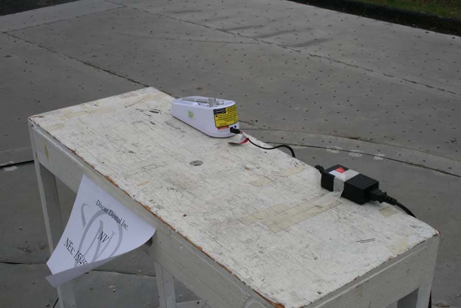
VIK-OH004
Mar 16, 2011Wireless Foot Pedal Switch
Equipment Class
DXX - Part 15 Low Power Communication Device Transmitter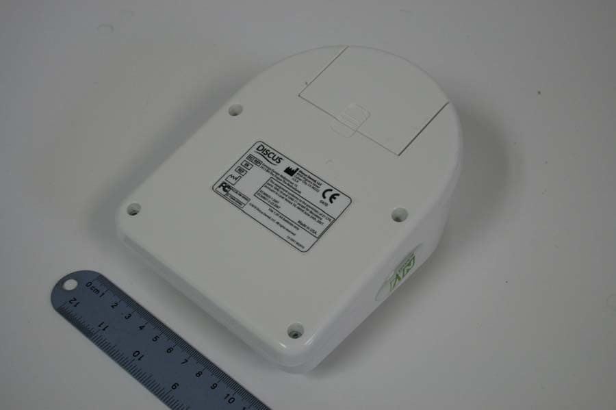
VIK-OH002
Mar 10, 2011Wireless Foot Pedal Switch
Equipment Class
DXX - Part 15 Low Power Communication Device Transmitter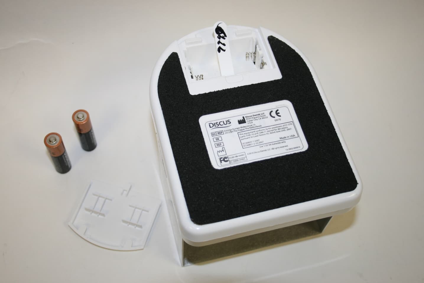
VIK-OH003
Feb 02, 2011Footpedal transmitter to operate dental laser surgical devices.
Equipment Class
DXX - Part 15 Low Power Communication Device Transmitter