Text extracted from the exhibit documents filed with the FCC. Open a document above to read the original.
Copyright © 2000-2013, Global Traffic Technologies, LLC 79-1000-0772-0 Revision B OPTICOMGPS3 Radio Transceiver Module User Manual Page 2 of 31 Copyright © 2000-2013, Global Traffic Technologies, LLC Ownership Disclaimer This document contains confidential information that is the sole property of Global Traffic Technologies (GTT) and is intended for use by their employees and designees. The user shall keep the contents of this document confidential and protect it from disclosure to outside parties. Any copying, distribution, or re-use, either in part or in whole, without the express written consent of Global Traffic Technologies is prohibited. Trademark Conventions The following is the list of registered trademarks of Global Traffic Technologies: Opticom® All instances of Opticom, Opticom Infrared and Opticom GPS contained within this document are understood to reference these trademarks without repeating the ® symbol. Page 3 of 31 Copyright © 2000-2013, Global Traffic Technologies, LLC Table of Contents 1. INTRODUCTION ........................................................................................................................... 4 1.1 Scope .......................................................................................................................................................................................... 4 1.2 Definitions, Acronyms, and Abbreviations ....................................................................................................................... 4 2. PROTOCOL SPECIFICATION ...................................................................................................... 5 2.1 Roles ............................................................................................................................................................................................ 5 2.2 Error Detection & Recovery................................................................................................................................................... 5 2.3 Flow Control .............................................................................................................................................................................. 5 2.4 Character Format ..................................................................................................................................................................... 5 2.5 Supported Data Types ............................................................................................................................................................ 6 2.6 Message Format ....................................................................................................................................................................... 6 3. SETUP AND CONFIGURATION MESSAGES .............................................................................. 8 3.1 Set Mode (M) .............................................................................................................................................................................. 8 3.2 Set Framing Configuration (F) .............................................................................................................................................. 9 3.3 Hop Table Configuration (H) ............................................................................................................................................... 10 3.4 Hop Table Row Index (I) ....................................................................................................................................................... 14 3.5 Transmit Slot Data (T) ........................................................................................................................................................... 15 3.6 Receive Slot Data (r) .............................................................................................................................................................. 16 3.7 Broken Mode Report (b) ....................................................................................................................................................... 17 3.8 Signal Strength Report (s) ................................................................................................................................................... 17 3.9 Set Serial Number (N) ............................................................................................................................................................ 18 3.10 Set Attenuation Level (G) ......................................................................................................................................................... 19 3.11 Erase Faults (J) ......................................................................................................................................................................... 20 4. QUERY MESSAGES ................................................................................................................... 21 4.1 Module Identity Query (D) .................................................................................................................................................... 21 4.2 Mode Query (Q) ....................................................................................................................................................................... 22 4.3 Framing Configuration Query (C) ...................................................................................................................................... 23 4.4 Hop Table Configuration Query (A) ................................................................................................................................... 24 4.5 Broken Mode (B) ..................................................................................................................................................................... 2…
Text truncated - open the document above for the full version.
Omap Processor VCOs / PLLs I/Q Modulator D A D A FSK Demodulator Serial Link D A X BPF X BPF LNA BPF PA LPF Baseband I/O DC Power RF I/O 1 PPS BPF 3.3V & 5.0V Module Block Diagram Tx Rx 24.576 MHz 24.00 MHz 2401 – 2483 MHz 2401 – 2483 MHz 2290 – 2373 MHz 121.29 MHz
Request for Confidentiality Date: November 8, 2013 Subject: Confidentiality Request for: FCC ID: VJB-OPTICOMGPS3 IC ID: 7275A-OPTICOM3 Pursuant to FCC 47 CRF 0.457(d) and 0.459 and IC RSP-100, Section 10, the applicant requests that a part of the subject FCC application be held confidential. Type of Confidentiality Requested Exhibit Short Term Permanent Block Diagrams Short Term External Photos Short Term Permanent* 1 Internal Photos Short Term Permanent Operation Description/Theory of Operation Short Term Permanent Parts List & Placement/BOM Short Term Permanent Tune-Up Procedure Short Term X Permanent Schematics Short Term Test Setup Photos Short Term Permanent* User’s Manual Global Traffic Technologies LLC has spent substantial effort in developing this product and it is one of the first of its kind in industry. Having the subject information easily available to "competition" would negate the advantage they have achieved by developing this product. Not protecting the details of the design will result in financial hardship. Permanent Confidentiality: The applicant requests the exhibits listed above as permanently confidential be permanently withheld from public review due to materials that contain trade secrets and proprietary information not customarily released to the public. Short-Term Confidentiality: The applicant requests the exhibits selected above as short term confidential be withheld from public view for a period of N/A days from the date of the Grant of Equipment Authorization and prior to marketing. This is to avoid premature release of sensitive information prior to marketing or release of the product to the public. Applicant is also aware that they are responsible to notify ACB in the event information regarding the product or the product is made available to the public. ACB will then release the documents listed above for public disclosure pursuant to FCC Public Notice DA 04-1705. NOTE for Industry Canada Applications: The applicant understands that until such time that IC distinguishes between Short Term and Permanent Confidentiality, either type of marked exhibit above will simply be marked Confidential when submitted to IC. 1 - The asterisked items (*) require further justification before permanent confidentiality will be allowed. These also currently require review by the FCC under their Permit-But-Ask policy before the grant is issued and can delay completion of an application. Further justification should be added to the note above. One such example for a potted device would be: “The EUT is FULLY potted using a non-removable epoxy based material. Removal of potting material causes irreparable damage to internal circuitry. See photographs exhibits that outline the device before and after potting.”
Authority to Act as Agent Date: November 8, 2013 American Certification Body, Inc. 6731 Whittier Avenue Suite C110 McLean, VA 22101 To Whom It May Concern: Thomas T. Smith, Ryan Urness and Amanda Hauck of LS Research, LLC is authorized to act on our behalf, until otherwise notified, for applications to American Certification Body, Inc. (ACB). We certify that we are not subject to denial of federal benefits, that includes FCC benefits, pursuant to Section 5301 of the Anti-Drug Abuse Act of 1988, 21 U.S.C. 862. Further, no party, as defined in 47 CFR 1.2002 (b), to the application is subject to denial of federal benefits, that includes FCC benefits. The term of this Agency Agreement shall start on the above date of this Agreement and shall continue in force until one (1) year thereafter. Thank you, Title: Director Market Development On behalf of: Global Traffic Technologies, LLC 7800 Third Street North Suite 100 St. Paul, MN 55128 Telephone: 651-789-7305
Re: Modular Transmitter Approval FCC ID: VJB-OPTICOMGPS3 To Whom It May Concern, The following information is being provided per the requirements of 15.212 regarding modular approval of Part 15 devices. This transceiver is a complete RF module with an integral reference oscillator. External connections are provided for power and data communication. The following numbered items correspond to similarly numbered paragraphs in 15.212. Each item is a response to the requirements of that document. 1) The module has integral RF shielding to isolate it from surrounding equipment and the larger environment in general. 2) All inputs are processed as data by the on-board microcontroller. The outside user has no direct control of transmit modulation. 3) There is a 3.0V voltage regulator on board that powers the radio transceiver. The power amplifier supply is monitored by the microcontroller and transmission is disabled if the source voltage is greater than 5.25V. 4) The antennas that are available with this device are. a. Laird # MAF94192 b. HOWTSEN # S-001-1 c. Mobile Mark # DM2-2400/1575 This is in accordance with Part 15.203. 5) The module was tested in a stand-alone configuration and found to be compliant with Part 15 regulations. 6) An FCC ID label is affixed to each unit at the time of manufacture. Information is also clearly presented in the user guide about labeling requirements for the final assembly. 7) This unit is compliant with Part 15.247. Installation and other requirements are presented in the user guide to allow the unit to be correctly installed. 8) The unit is compliant with the RF exposure requirements of Parts 15.247 and 2.1091. Further information may be obtained from: Global Traffic Technologies LLC Sincerely, Title: Director Market Development On behalf of: Global Traffic Technologies, LLC 7800 Third Street North Suite 100 St. Paul, MN 55128 Telephone: 651-789-7305 AS of May 2, 2008, according to new "Authorized Individual Policy" of the FCC, all the letters from the applicant must be signed by the person seen in the FCC database as the contact for the grantee code
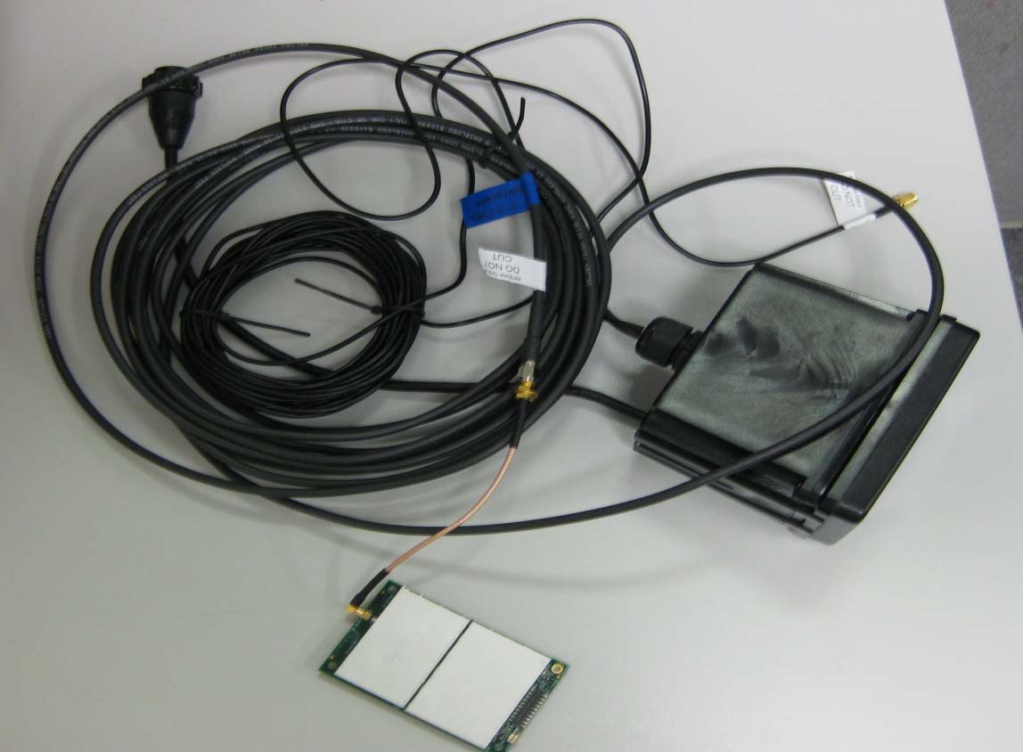
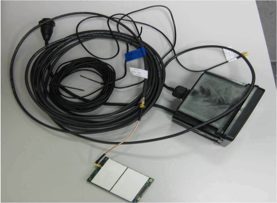
EXTERNAL PHOTOS Company Name Global Traffic Technologies LLC Model # OPTICOMGPS3 FCC ID # VJB‐OPTICOMGPS3 IC # 7275A‐OPTICOM3 Page 1 of 5 Back side of board Front side of board EXTERNAL PHOTOS Company Name Global Traffic Technologies LLC Model # OPTICOMGPS3 FCC ID # VJB‐OPTICOMGPS3 IC # 7275A‐OPTICOM3 Page 2 of 5 Cable attached to board EXTERNAL PHOTOS Company Name Global Traffic Technologies LLC Model # OPTICOMGPS3 FCC ID # VJB‐OPTICOMGPS3 IC # 7275A‐OPTICOM3 Page 3 of 5 HOW TSEN # S-00101 Dipole Antenna attached to board EXTERNAL PHOTOS Company Name Global Traffic Technologies LLC Model # OPTICOMGPS3 FCC ID # VJB‐OPTICOMGPS3 IC # 7275A‐OPTICOM3 Page 4 of 5 Mobile Mark #DM2-2400/1575Antenna Laird #MAF94192 LED Emitter with internal antenna EXTERNAL PHOTOS Company Name Global Traffic Technologies LLC Model # OPTICOMGPS3 FCC ID # VJB‐OPTICOMGPS3 IC # 7275A‐OPTICOM3 Page 5 of 5 Internal antenna of Laird #MAF94192
ID LABEL PHOTOS Company Name Global Traffic Technologies LLC Model # OPTICOMGPS3 FCC ID # VJBOPTICOMGPS3 IC # 7275A‐OPTICOM3 Page 1 of 1 The label material is Lexan 8B35 Velvet Matt Polycarbonate, 10 mil thick with 3M 467 MP adhesive.
INTERNAL PHOTOS Company Name Global Traffic Technologies LLC Model # OPTICOMGPS3 FCC ID # VJB‐OPTICOMGPS3 IC # 7275A‐OPTICOM3 Page 1 of 2 INTERNAL PHOTOS Company Name Global Traffic Technologies LLC Model # OPTICOMGPS3 FCC ID # VJB‐OPTICOMGPS3 IC # 7275A‐OPTICOM3 Page 2 of 2
GTT MODULE THEORY OF OPERATION Prepared by Last updated On 1/9/201 4 TITLE: GTT Module Theory of Operation DATE: 1/9/1 4 FILENAME: GTT Theory of Operation.docx REVISION: 2.0 PAGE: Page 1 of 6 Table of Contents 1 Introduction .................................................................................................................. 3 1.1 Purpose & Scope ......................................................................................................................... 3 1.2 Background / Technology ............................................................................................................ 3 2 Module Theory of Operation ........................................................................................ 5 2.1 Overview ...................................................................................................................................... 5 2.2 Transceiver System ..................................................................................................................... 5 2.2.1 Receiver .................................................................................................................................. 5 2.2.2 Transmitter .............................................................................................................................. 5 2.2.3 Channel Selection ................................................................................................................... 6 TITLE: GTT Module Theory of Operation DATE: 1/9/14 FILENAME: GTT Theory of Operation.docx REVISION: 2.0 PAGE: Page 2 of 6 1 Introduction 1.1 PURPOSE & SCOPE The purpose of this document is to provide theory of operation for the module design of a 2.4GHz FHSS / TDMA radio module for GTT. 1.2 BACKGROUND / TECHNOLOGY The GPS based priority control system uses a proprietary 2.4 GHz FHSS/TDMA transceiver to transfer data between any vehicles, and traffic intersection controllers within radio range. Figure 1 provides a block diagram one node in the system. Remotely Mounted Radio Transmitter/Reciever Baseband Processor Media Access Control RS485 Serial Port Power Supply 1 PPS, Data, Power Figure 1: GTT Module Block Diagram – High-Level TITLE: GTT Module Theory of Operation DATE: 1/9/14 FILENAME: GTT Theory of Operation.docx REVISION: 2.0 PAGE: Page 3 of 6 Figure 2 provides some High-level specifications for module design. SPECIFICATIONS GTTMODULE Frequency2400– 2483.5MHz TX Power +27 dBm RF Data Rate384.0kpbs RF ModulationFiltered FSK Operating Temp‐35 to +75C Figure 2: GTT Module General Specifications TITLE: GTT Module Theory of Operation DATE: 1/9/14 FILENAME: GTT Theory of Operation.docx REVISION: 2.0 PAGE: Page 4 of 6 2 Module Theory of Operation 2.1 OVERVIEW The module is a half duplex (transmit or receive) transceiver. Figure 3 shows a top level block diagram of the module. Module Block Diagram Baseband I/O Serial Link D A I/Q D Modulator A Tx BPF PA LPF 2401 – 2483 MHz 1 PPS Omap Processor VCOs / PLLs 2290 – 2373 MHz RF I/O 2401 – 2483 MHz 3.3V & 5.0V DC Power 24.00 MHz 24.576 MHz D FSK A Demodulator 121.29 MHz BPF X Rx BPF X LNA BPF Figure 3: Radio Top Level Block Diagram 2.2 TRANSCEIVER SYSTEM 2.2.1 Receiver The receiver is a dual conversion design with a FSK discriminator based demodulator. The discriminator output is connected to an A/D converter. The A/D converter samples the discriminator output using multiple samples per bit. The A/D converter is connected to a high speed data port (uPP) on the processor. The Omap processor recovers the data using signal processing algorithms. The first IF frequency is 110.59 MHz and the second IF is 10.7 MHz. 2.2.2 Transmitter In order to duplicate the modulation of the legacy system without the need for tuning, the modulation is performed digitally. The processor calculates the in-phase and quadrature components of the signal. The signal is transferred to a pair D/A converters which directly modulates the RF carrier signal. The output of the RF modulator is bandpass filtered, and then drives the RF power amplifier. The frequency of the oscillator the feeds the modulator is at the TITLE: GTT Module Theory of Operation DATE: 1/9/14 FILENAME: GTT Theory of Operation.docx REVISION: 2.0 PAGE: Page 5 of 6 transmit frequency. The RF amplifier output is lowpass filtered before connecting to the antenna. Output power is adjustable by means of a programmable attenuator following the modulator but before the power amplifier. 2.2.3 Channel Selection Frequency selection is by means of an integrated phase lock loops and local oscillators. The three oscillators will only have to tune to a new hop frequency and not from receiver IF frequency to transmit frequency during the frame. Since this only has to be done once per frame, it allows longer tuning time and lower phase noise of the oscillators. PSEUDORANDOM HOPPING SEQUENCE. A new hop channel is selected every 333ms. 2 50 58 4 52 6 8 60 10 48 42 12 46 44 40 62 38 64 14 16 66 18 32 20 68 22 30 72 1 74 34 36 24 28 26 3 70 53 5 55 59 9 49 7 47 51 11 45 61 13 63 41 39 15 43 65 19 37 67 69 17 21 73 31 29 33 71 75 27 35 25 23 56 57 54 RECEIVER SYNCHRONIZATION AND RECEIVER INPUT BANDWIDTH. The receiver input bandwidth is 1.1 MHz. The receiver is a dual conversion design with a FSK discriminator based demodulator. The discriminator output is connected to an A/D converter. TITLE: GTT Module Theory of Operation DATE: 1/9/14 FILENAME: GTT Theory of Operation.docx REVISION: 2.0 PAGE: Page 6 of 6
W66 N220 Commerce Court ● Cedarburg, WI 53012 ● USA Phone: 262.375.4400 ● Fax: 262.375.4248 www.lsr.com TEST REPORT # 313269 LSR Job #: C-1822 Compliance Testing of: Opticom GPS Priority System with Dipole Antenna, Mobile Mark Antenna & Multi-Mode Emitter Antenna Test Date(s): September 19-26 th , October 8-10, 2013 Prepared For: Attn: Timothy J. Hall Global Traffic Technologies, LLC 7800 Third Street North BLDG 100 Saint Paul, MN 55128 In accordance with: Federal Communications Commission (FCC) Part 15, Subpart C, Section 15.247 Industry Canada (IC) RSS 210 Annex 8 Frequency Hopping Spread Spectrum (FHSS) Operating in the Frequency Band 2400-2483.5 MHz This Test Report is issued under the Authority of: Peter Feilen, EMC Engineer Signature: Date: 12/19/13 Test Report Reviewed by: Shane Rismeyer, EMC Engineer Signature: Date: 12/18/13 Tested by: Peter Feilen, EMC Engineer Signature: Date: 10/10/13 This Test Report may not be reproduced, except in full, without written approval of LS Research, LLC. Prepared For: Global Traffic Technologies EUT: Opticom GPS Priority System LS Research, LLC Report # 313269 Model #: OPTICOMGPS3 LSR Job #: C-1822 Serial#: Engineering Sample Page 2 of 48 TABLE OF CONTENTS EXHIBIT 1. INTRODUCTION ............................................................................................................. 4 1.1 - Scope .................................................................................................................................. 4 1.2 – Normative References ....................................................................................................... 4 1.3 - LS Research, LLC Test Facility .......................................................................................... 5 1.4 – Location of Testing ............................................................................................................. 5 1.5 – Test Equipment Utilized ..................................................................................................... 5 EXHIBIT 2. PERFORMANCE ASSESSMENT ................................................................................... 6 2.1 – Client Information ............................................................................................................... 6 2.2 - Equipment Under Test (EUT) Information .......................................................................... 6 2.3 - Associated Antenna Description ......................................................................................... 6 2.4 EUT’S Technical Specifications ........................................................................................... 7 2.5 Product Description .............................................................................................................. 8 EXHIBIT 3. EUT OPERATING CONDITIONS & CONFIGURATIONS DURING TESTS ................... 9 3.1 - Climate Test Conditions ...................................................................................................... 9 3.2 - Applicability & Summary Of EMC Emission Test Results ................................................... 9 3.3 - Modifications Incorporated In The EUT For Compliance Purposes .................................... 9 3.4 - Deviations & Exclusions From Test Specifications ............................................................. 9 EXHIBIT 4. DECLARATION OF CONFORMITY .............................................................................. 10 EXHIBIT 5. RADIATED EMISSIONS TEST ...................................................................................... 11 5.1 Test Setup .......................................................................................................................... 11 5.2 Test Procedure ................................................................................................................... 11 5.3 Test Equipment Utilized ..................................................................................................... 11 5.4 Test Results ....................................................................................................................... 11 5.5 Calculation of Radiated Emissions Limits .......................................................................... 12 5.6 Radiated Emissions Test Data Chart – Transmit Mode ..................................................... 13 5.8 Screen Captures – Transmit Mode .................................................................................... 15 5.9 Receive Mode Testing ....................................................................................................... 18 5.10 Screen Captures - Receive Mode .................................................................................... 19 EXHIBIT 6. CONDUCTED EMISSIONS TEST, AC POWER LINE .................................................. 21 EXHIBIT 7. OCCUPIED BANDWIDTH ............................................................................................. 22 7.1 Method of Measurements .................................................................................................. 22 7.2 Limit .................................................................................................................................... 22 7.3 Test Results ....................................................................................................................... 22 7.4 - Test Data .......................................................................................................................... 22 7.5 Screen Captures ................................................................................................................ 23 Prepared For: Global Traffic Technologies EUT: Opticom GPS Priority System LS Research, LLC Report # 313269 Model #: OPTICOMGPS3 LSR Job #: C-1822 Serial#: Engineering Sample Page 3 of 48 EXHIBIT 8. BAND-EDGE MEASUREMENTS ......................................................................…
Text truncated - open the document above for the full version.
TEST SETUP PHOTOS Company Name Global Traffic Technologies LLC Model # OPTICOMGPS3 FCC ID # VJBOPTICOMGPS3 IC # 7275A‐OPTICOM3 Page 1 of 4 TEST SETUP PHOTOS Company Name Global Traffic Technologies LLC Model # OPTICOMGPS3 FCC ID # VJBOPTICOMGPS3 IC # 7275A‐OPTICOM3 Page 2 of 4 TEST SETUP PHOTOS Company Name Global Traffic Technologies LLC Model # OPTICOMGPS3 FCC ID # VJBOPTICOMGPS3 IC # 7275A‐OPTICOM3 Page 3 of 4 TEST SETUP PHOTOS Company Name Global Traffic Technologies LLC Model # OPTICOMGPS3 FCC ID # VJBOPTICOMGPS3 IC # 7275A‐OPTICOM3 Page 4 of 4
7800 Third Street North · Saint Paul, Minnesota · United States
| # | Rule Parts | Frequency Range | Power Output |
|---|---|---|---|
| 1 | 15C | 2.40 GHz - 2.48 GHz | 724.00 mW |

Opticom Radio Transceiver
Equipment Class
DSS - Part 15 Spread Spectrum Transmitter