VJRTAG-142COMPACT TAG
Activewave, Inc.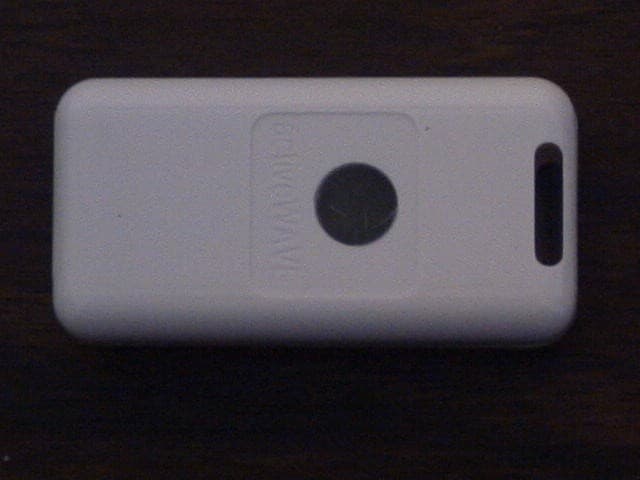
Click to zoom
Application Details
- Equipment Class
- DXX - Part 15 Low Power Communication Device Transmitter
- Date of Grant
- Sep 18, 2007
- Application Purpose
- Original Equipment
- Date of Application
- Sep 18, 2007
- Equipment Note
- COMPACT TAG
- Frequency Range
- 916.50000000 - 916.50000000
- Company
- Activewave, Inc.
- Country
- United States
Documents & Files
Document Text
Text extracted from the exhibit documents filed with the FCC. Open a document above to read the original.
Users Manual
ActiveWave Inc. Active RFID Reader Service Manual 1 Service Manual for Active RFID Compact Tag Version: 2.00 ActiveWave, Inc. 902 Clint Moore Road Suite 118 Boca Raton, FL 33487 Tel: 561.999.9423 Fax: 561.999.9428 www.activewaveinc.com ActiveWave Inc. Active RFID Reader Service Manual 2 Table of Contents 1 Introduction...................................................................................................................... 4 2 Product Overview ............................................................................................................ 4 2.1 CardTag.....................................................................................................................5 2.2 CompactTag .............................................................................................................. 6 2.3 MiniTag.....................................................................................................................7 2.4 WristbandTag............................................................................................................ 8 2.5 JumboTag.................................................................................................................. 9 3 Part Numbers .................................................................................................................10 4 Troubleshooting Guide .................................................................................................. 12 5 Dismantling the Tag....................................................................................................... 13 6 Re-assembly Instructions ............................................................................................... 13 7 Preparing for First Time Use ......................................................................................... 13 8 Testing............................................................................................................................ 16 9 Circuit Diagram ............................................................................................................. 17 10 FCC ID .................................................................................... ......19 11 Warning ..........................................................................................19 12 FCC 15-21 warning..............................................................................19 ActiveWave Inc. Active RFID Reader Service Manual 3 NOTE This unit contains CMOS devices that may be damaged by electrostatic discharge (ESD). The following steps to minimize ESD must be taken before the unit is dismantled. To prevent any damage that could result if the unit or its parts are not handled properly, observe the following precautions during any handling procedures: • Minimize all handling of static-sensitive components and assemblies. • Transport and store static-sensitive components and assemblies in their original containers or anti-static bags. • Label accordingly any package that contains static-sensitive components or assemblies. • Discharge static electricity from the body by wearing a grounded anti-static wrist strap while handling these components. Servicing static-sensitive components or assemblies should be done only at a static-free workstation by qualified service technicians. • Increasing the humidity in the work area minimizes static electricity problems. • Do not allow anything that can generate or hold a static charge on the workstation surface. • Pick up components by their bodies, never by their leads. • Do not slide components over any surface. • Avoid handling components in areas with a floor or work-surface covering that can generate static charge. ActiveWave Inc. Active RFID Reader Service Manual 4 1 Introduction The purpose of this service manual is to give an overview of the service procedures that may need to be performed by either a third party user, or an authorized ActiveWave service technician. It has been designed to be used by service and repair technicians who are responsible for maintaining the products. The tag uses both conventional and high-density surface mount component technology, which requires specialist-servicing techniques. We therefore recommend that repairs be carried out at circuit board level, rather than at component level. Since the tag only consists of one board, we recommend replacing the entire tag for most issues related to hardware failures. We encourage service technicians to carry a small buffer stock of replaceable tags, to allow immediate exchange, should they need to be replaced. 2 Product Overview ActiveWave tags can be used to track and monitor people, assets, or inventory items in an office, warehouse, or any other type of facility. For example, our tags can be configured to track employees in an office, locate heart monitors in a hospital, find specific pallets in a warehouse – basically any application that requires system monitoring of anything. When tags are used on both people and assets, all movement of valuable assets without an assigned owner will automatically generate system alarms and can securely lock exit doors. ActiveWave offers the following different types of active RFID tags: • cardTag • compactTag • wristbandTag • miniTag • jumboTag All of these tags have the following features: 1. enable/disable 2. group calls 3. low battery indicator 4. configurable ID and type 5. configurable random response delays 6. configurable no. of transmit packets ActiveWave Inc. Active RFID Reader Service Manual 5 7. configurable resend of data in field 8. configurable resend of data out of field (beacon) 9. configurable assigned reader ID In addition, some or all of the tags have the following options: 1. optional temperature sensor 2. optional tamper switch 3. optional user-definable memory 4. optional LED 5. optional buzzer 6. replaceable battery 2.1 CardTag Figure 1: ActiveWave CardTag CardTag Specifications: • User Memory: 0 - 256 Kbi…
Text truncated - open the document above for the full version.
Cover Letter(s)
Federal Communications Commission Authorization and Evaluation Division Confidentiality Request regarding application for certification of FCC ID: VJRTAG-142. Pursuant to Sections 0.457 and 0.459 of the Commission’s Rules, we hereby request confidential treatment of information accompanying this application as outlined below: Block Diagram - 2784UT7 Blockdiagram.pdf Operational Description 2784UT7 Operationaldesc.pdf Schematics 2784UT7 Schematics.pdf The above materials contain trade secrets and proprietary information not customarily released to the public. The public disclosure of these materials may be harmful to the applicant and provide unjustified benefits to its competitors. The applicant understands that pursuant to Section 0.457 of the Rules, disclosure of this application and all accompanying documentation will not be made before the date of the Grant for this application. We understand that the above exhibits have been viewable on the FCC web site since the date of the grant. Sincerely, _______________________________________ Signature Attached: Copy of FCC Confidentiality Policy 902 Clint Moore Rd, Suit 118 Boca Raton, FL 33487 Tele (561) 999-9422 Fax (561) 999-9428
External Photos
ACTIVE WAVE INC. FCC ID: VJRTAG-142 EXTERNAL PHOTOS
ID Label/Location Info
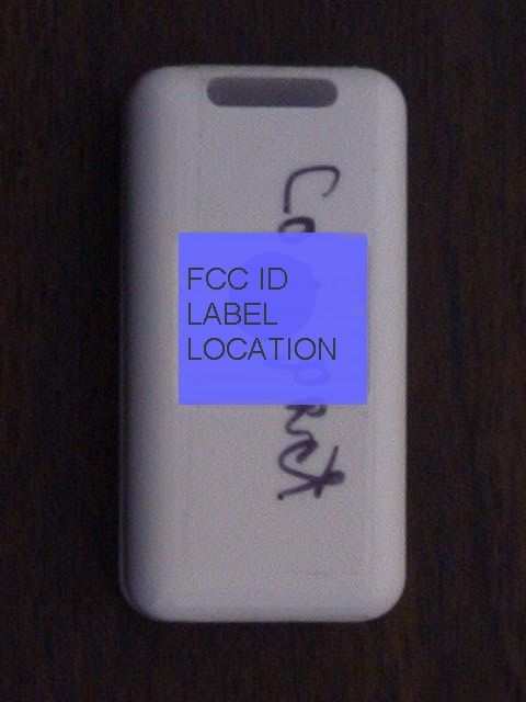
COMPACT TAG FCC ID: VJRTAG-142 THIS DEVICE COMPLIES WITH PART 15 OF THE FCC RULES. OPERATION IS SUBJECT TO THE FOLLOWING TWO CONDITIONS: (1) THIS DEVICE MAY NOT CAUSE HARMFUL INTERFERENCE, AND (2) THIS DEVICE MUST ACCEPT ANY INTERFERENCE RECEIVED, INCLUDING INTERFERENCE THAT MAY CAUSE UNDESIRED OPERATION.
Internal Photos
ACTIVE WAVE INC. FCC ID: VJRTAG-142 INTERNAL PHOTOS
Test Report
EMI Research and Development Laboratory Department of Electrical Engineering Florida Atlantic University 3998 FAU Blvd., Suite 310 Boca Raton, Flroida 33431 (561) 338-1650 FCC PART 15.249 TEST REPORT Applicant ACTIVE WAVE, INC. Address 902 CLINT MOORE ROAD SUITE 118 BOCA RATON, FL 33487 FCC ID VJRTAG-142 Product Description COMPACT TAG Date Sample Received JULY 18, 2005 Date Tested AUGUST 24, 2005 Tested By RAYMOND AINA Approved By VICHATE UNGVICHIAN Test Results PASS FAIL FAU EM I R&D LAB EMI Research and Development Laboratory Department of Electrical Engineering Florida Atlantic University 3998 FAU Blvd, Suite 310 Boca Raton, Florida 33431 (561) 338-1650 Technical Report No. 05-041-11 "EMI Evaluation of the Active Wave Compact Tag to FCC Part 15 Unintentional Radiators, Class A, Radiated Emission Requirements and Intentional Radiators, Section 15.249 Performed: 18 July – 24 August, 2005 Customer: Active Wave, Inc. Attn: Arnold Banks 902 Clint Moore Road, Suite 118 Boca Raton, FL 33487 Company Official responsible for product(s) tested: _______________________________ Arnold Banks, Engineer 561-999-9423 Test Performed and Reported By: _______________________________ Raymond Aina, BSEE, BSME FAU EMI R&D Laboratory Approved by: ________________________________ Vichate Ungvichian, Ph.D., P.E. Director, FAU EMI R&D Laboratory 2129.01 Technical Report 05-041-11 1. INTRODUCTION The active Wave Compact Tag is a transceiver, which is capable to transmit at 916.5 MHz and receive at 433.92 MHz via an internal antenna. During the transmission, the receiving section was automatically deactivated. The unit was powered by a 3-Volt Lithium Battery (Model 2032). Evaluation results reported herein apply only to the specific items of equipment, configurations (including software and unit operation), and procedures supplied to the Florida Atlantic University EMI Research Lab by Active Wave, Inc. under the test conditions listed herein. 2. OBJECTIVE This evaluation was performed to verify the conformance of the Active Wave Compact Tag with reference to the U.S. Federal Communications Commission (FCC) Code of Federal Regulations (CFR), Title 47- Telecommunication, FCC Part 15 Subpart B- Unintentional Radiators, Section 15.109 (b) and radiated emissions. In addition to FCC Part 15, Subpart C- Intentional Radiators, the unit must comply with Section 15.249, operating within the band 902-928 MHz. 3. CONCLUSION The Active Wave Compact Tag met the FCC Class A radiated emission requirements and the FCC Part 15, Sec tion 15.249 as described in the following pages. Technical Report 05-041-11 3 4. TEST PROCEDURES AND RESULTS 4.1 TEST PROCEDURES The measurement techniques identified in the measurement procedure of ANSI C63.4-2001 "American National Standard of Measurement of Radio-Noise Emissions from Low-Voltage Electrical and Electronic Equipment in the Range of 9 kHz to 40 GHz" were followed as close as practical during this evaluation. Complete details and specific procedures used are discussed in the respective Test Result sections. 4.2 TEST RESULTS 4.2.1 CONDUCTED POWERLINE EMISSIONS Since the Compact Tag is a battery powered device, no conducted evaluation was required. 4.2.2 RADIATED EMISSIONS The Active Wave Compact Tag was set up on a wooden turntable 80 centimeters above the ground plane of the FAU 3-m Semi-anechoic chamber, which is an FCC listed and A2LA registered site. The unit was programmed to operate in a receiving mode for section 15.109 (b). For an intentional radiator, Section 15.249, the unit was programmed to transmit at 916.5 MHz. Photographs 1 and 2 show the set up used during the radiated emissions testing. PHOTOGRAPHS 1 & 2: RADIATED EMISSION TEST SET UP Technical Report 05-041-11 Technical Report 05-041-11 6 4.2.2.1 Unintentional Radiator, Radiated Emission Limits, Sections 15.109 An EMCO 3104 Broadband Biconical antenna was installed on an EMCO pneumatically controlled Antenna Mast at a distance of 3 meters from the system. The 30 MHz to 200 MHz frequency range was automatically scanned on the HP 8566B Spectrum Analyzer operated in the peak detector mode with a bandwidth of 120 kHz obtained through the HP 85650A Quasi Peak Adapter. It should be noted that the RES BW and VBW of the spectrum analyzer must be set to 1 MHz for the Quasi Peak Adaptor to provide 120 kHz bandwidth correctly. Hence, in the figures RES BW and VBW are still indicated as 1 MHz. The Biconical antenna was oriented horizontally polarized to the measured field and was initially set 1-m above the floor. After setting the SA to operate between 30-200 MHz, the max hold switch on the SA was pressed. The turntable was then rotated 360 degrees. After the completion, the turntable was rotated back to the previously noted azimuth angles where the strongest E-field occurred, and the antenna was then scanned in height from 1-4 meters at those angles to obtain the maximum value. The composite field trace was then plotted. The antenna was then rotated to measure the vertical polarized E-field. The clear write switch was pressed, then the max hold switch was pressed, and the above procedure was repeated. For the 200-1000 MHz band, a Log Periodic antenna (EMCO 3146) was installed and the SA was set to operate between 200-1000 MHz. To collect data, the above measurement procedures were then repeated. Figures 1-4 show the worse case radiated emissions, independent of azimuth or antenna height, which are below the required Class A limits. The limit lines have been corrected for the appropriate antenna factor, cable loss, amplifier gain, and distance factor based on the following equation: E (dBμV/m) = SA reading (dBμV) + Antenna Factor (dB/m) + Cable Loss (dB) - Amp Gain (dB) – Corrected Distance Factor (dB). The correction factor for Class A is 20xlog [10/3] which is equal to 10.45 dB FIGURE 1: RADIATED EMISSIONS (30 - 200 MHz HORIZONTAL) Technical Report 05-041-11 7 FIGURE 2: RADIATED EMISSIONS (30 - 200 MHz VERTICAL) Technical Repor…
Text truncated - open the document above for the full version.
Test Report
ACTIVE WAVE INC. FCC ID: VJRTAG-142 OCCUPIED BANDWIDTH PLOT CALCULATION OF DUTY CYCLE The period of the pulse train is determined by observing it on an oscilloscope or a spectrum analyzer with zero (0) frequency span. A plot is then made of the pulse train with a sweep time of 100 milliseconds. This sweep determines the duration of the pulse train. This sweep allows the determination of the number of and type of pulses, i.e. long & short. Plots are then made showing the duration of each type of pulse and its duration. From the 100 ms plot, the number of a given type of pulse is then multiplied by the duration of that type pulse. This allows the calculation of the amount of time the DUT is on within 100 ms. If the pulse train is longer than 100 ms then this number is multiplied by 100 to determine the percentage “ON TIME”. If the pulse train is less than 100 ms the total on time is divided by the length of the pulse train and then multiplied by 100 to determine the percentage “ON TIME”. The average field strength is determined by multiplying the peak field strength by the percent “ON TIME” in dB’s. Duration of all long pulse = Duration of all short pulses = Total on time = 26.6 ms The period = 100 ms dB = 20*log(ON TIME)/PERIOD dB = 20*log(26.6/100) dB = 11.5 dB In this case the whole pulse train is considered on time and the period is taken as 100ms. The manufacturer considers this worst case.
Test Setup Photos
4.2.2 RADIATED EMISSIONS The Active Wave Compact Tag was set up on a wooden turntable 80 centimeters above the ground plane of the FAU 3-m Semi-anechoic chamber, which is an FCC listed and A2LA registered site. The unit was programmed to operate in a receiving mode for Section 15.109 (b). For an intentional radiator, Section 15.245 (b), the unit was programmed to transmit at 916.5 MHz. Photographs 1 and 2 show the set up used during the radiated emissions testing. PHOTOGRAPHS 1 & 2: RADIATED EMISSION TEST SETUP Technical Report 05-041-11 5
Contact Information
Applicant
Touraj Ghaffari(Owner)
Test Firm
ADVANCED COMPLIANCE SOLUTIONS, INC.Vichate Ungvichian
Technical Specifications
| # | Rule Parts | Frequency Range | Power Output |
|---|---|---|---|
| 1 | 15C | 916.5 MHz - 916.5 MHz | - |
Other Applications from Activewave, Inc.
VJRTAG-143-144
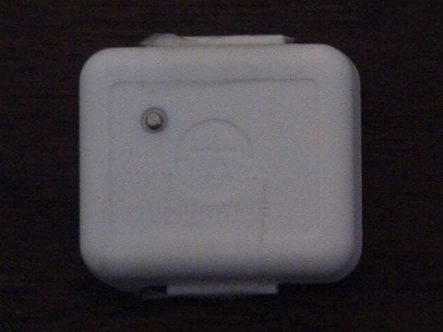
Sep 19, 2007MINI TAG AND WRIST TAG
Equipment Class
DXX - Part 15 Low Power Communication Device Transmitter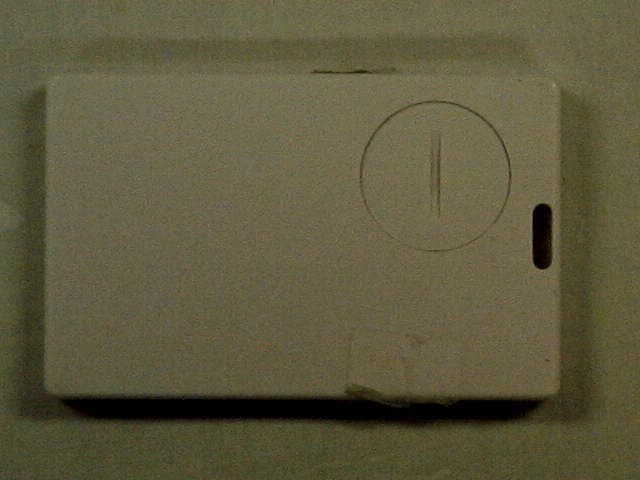
VJRTAG-141-145
Sep 18, 2007CREDIT CARD AND JUMBO TAG
Equipment Class
DXX - Part 15 Low Power Communication Device Transmitter