VK7SLEI1010000PStair Night Light Unit A (TX)
MAINSTAR ELECTRICAL COMPANY LTD.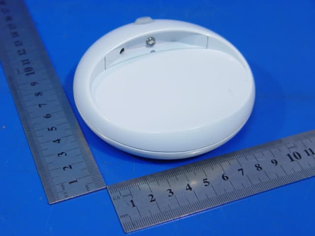
Click to zoom
Application Details
- Equipment Class
- DSR - Part 15 Remote Control/Security Device Transceiver
- Date of Grant
- Mar 04, 2008
- Application Purpose
- Original Equipment
- Date of Application
- Mar 04, 2008
- Equipment Note
- Stair Night Light Unit A (TX)
- Frequency Range
- 315.00000000 - 315.00000000
- Country
- China
Documents & Files
Document Text
Text extracted from the exhibit documents filed with the FCC. Open a document above to read the original.
Users Manual
PIR RF Staircase/Hallway Night Light System User manual The product is a PIR RF Stair Night Light System, it consists of 2 Unit, Unit A PIR RF transceiver and Unit B Receiver Unit A is a PIR motion detector, when motion is detected within 2 meters area from Unit A, Unit A transmit a 315MHz ASK coded signal of approximate 1 second, and the LED light of Unit A will power on for about 1 minute, then the LED goes off automatically. The Unit B will aslo power on the LED light for about 1 minute after the RF signal from Unit A is received. 315MHz receiver function is deployed in the 2 Unit A, when a Unit A received RF signal from the other, the LED light will power on for about 1 minute. CDS photosensitive detector is deployed in Unit A, and Unit A operates only at night and in dark places. Power supply: AA alkaline * 3 (4.5V) Installation height: approximate 30-50cm Installation location: Unit A- top and bottom of the stairs, Unit B- staircase Operation description: After the battery is installed in Unit A, when the illumination intensity is under 0.15LUX and motion is detected by the PIR sensor within 3 meters from the Unit, Unit A transmit a 315Mhz ASK modulated RF signal. The signal is received and decoded by another Unit A or Unit B, if the code received is identical to the code stored, the LED light is power on for 60 seconds, then goes off automatically. FCC INFORMATION This device complies with Part 15 of the FCC Rules. Operation is subject to the following two conditions: (1) this device may not cause harmful interference, and (2) this device must accept any interference received, including interference that may cause undesired operation. Changes or modifications not expressly approved by the party responsible for compliance could void the user's authority to operate the equipment. This equipment complies with FCC radiation exposure limits set forth for an uncontrolled environment. End users must follow the specific operating instructions for satisfying RF exposure compliance. This transmitter must not be co-located or operating in conjunction with any other antenna or transmitter. This device complies with FCC RF radiation exposure limits set forth for an uncontrolled environment. The antenna used for this transmitter must be installed to provide a separation distance of at least 20 cm from all persons and must not be co-located or operating in conjunction with any other antenna or transmitter.
Cover Letter(s)
DATE Equipment Autorisation Division Federal Communications Commission 7435 Oakland Mills Road Columbia, MD 21046 FCC ID:_ VK7SLEI1010000P _ _ Product Name:_ Stair Night Light __ Request for Confidentiality Pursuant to Sections 0.457 and 0.459 of the commissions rules, we hereby request that the following documents be held confidential: • Schematics • Block diagram • Technical description These materials contain trade secrets and proprietary information and are not customarily released to the public. The public disclosure of this information might be harmful to the company and provide unjustified benefits to our competitors. Dated this Day of Jan 8 2008 By: Chiu Bit Hon Signature Printed Title: Manager of Safety & Regulatory On behalf of : Mainstar Electrical Company Ltd. Telephone: +86 769 85649233
External Photos
Report No.: WT078003133 Page 23/27 Photo 1 Appearance of EUT Photo 2 Appearance of EUT
ID Label/Location Info
This device complies with Part 15 of the FCC Rules. Operation is subject to the following two conditions: (1) this device may not cause harmful interference, and (2) this device must accept any interference received, including interference that may cause undesired operation. FCC ID: VK7SLEI1010000P
Internal Photos
Report No.: WT078003133 Page 24/27 Photo 3 Inside of EUT Photo 4 Inside of EUT Report No.: WT078003133 Page 25/27 Photo 5 Inside of EUT Photo 6 Inside of EUT Report No.: WT078003133 Page 26/27 Photo 7 Inside of EUT Photo 8 Inside of EUT Report No.: WT078003133 Page 27/27 Photo 9 Inside of EUT Photo 10 Inside of EUT
Test Report
Page 1/27 EMC TEST REPORT For Stair Night Light Model Number: SL-EI-101-00-00P FCC ID: VK7SLEI1010000P Report Number : WT078003133 Test Laboratory : Shenzhen Academy of Metrology and Quality Inspection EMC Laboratory Guangdong EMC Compliance Test Center Site Location : Bldg. of Metrology &Quality Inspection, Longzhu Road, Shenzhen, Guangdong, China Tel : 0086-755-26941637, 26941529, 26941531 Fax : 0086-755-26941545 Email : [email protected] Report No.: WT078003133 Page 2/27 TABLE OF CONTENTS TEST REPORT DECLARATION ........................................................................................................3 1. TEST RESULTS SUMMARY ...................................................................................................4 2. GENERAL INFORMATION ....................................................................................................5 2.1. Report information ............................................................................................................5 2.2. Laboratory Accreditation and Relationship to Customer .................................................5 2.3. Measurement Uncertainty .................................................................................................5 3. PRODUCT DESCRIPTION ......................................................................................................6 3.1. EUT Description ...............................................................................................................6 3.2. Related Submittal(s) / Grant (s) ........................................................................................6 3.3. Block Diagram of EUT Configuration..............................................................................6 3.4. Operating Condition of EUT ............................................................................................6 3.5. Test voltage .......................................................................................................................6 3.6. Special Accessories...........................................................................................................6 3.7. Equipment Modifications..................................................................................................6 3.8. Support Equipment List ....................................................................................................6 3.9. Test Conditions .................................................................................................................7 4. TEST EQUIPMENT USED .......................................................................................................7 5. CONDUCTED DISTURBANCE TEST ....................................................................................8 5.1. Test Standard and Limit ....................................................................................................8 5.2. Test Procedure ..................................................................................................................8 5.3. Test Arrangement..............................................................................................................8 5.4. Test Data ...........................................................................................................................8 6. RADIATED DISTURBANCE TEST ........................................................................................9 6.1. Test Standard and Limit ....................................................................................................9 6.2. Test Procedure ................................................................................................................10 6.3. Test Arrangement............................................................................................................10 6.4. Test Data .........................................................................................................................10 7. OCCUPIED BANDWIDTH .....................................................................................................14 7.1. Test Standard and Limit ..................................................................................................14 7.2. Test Procedure ................................................................................................................14 7.3. Test Arrangement............................................................................................................14 7.4. Test Data .........................................................................................................................14 8. DEACTIVATION TIME..........................................................................................................16 8.1. Test Standard and Limit ..................................................................................................16 8.2. Test Procedure ................................................................................................................16 8.3. Test Arrangement............................................................................................................16 8.4. Test Data .........................................................................................................................16 9. ANTENNA REQUIREMENT .................................................................................................18 9.1. STANDARD APPLICABLE..........................................................................................18 9.2. ANTENNA CONNECTED CONSTRUCTION ............................................................18 10. TABLE LIST .............................................................................................................................19 APPENDIX I TEST SETUP PHOTOS...............................................................................................20 APPENDIX II EUT PHOTOS .......................................................…
Text truncated - open the document above for the full version.
Test Setup Photos
Report No.: WT078003133 Page 20/27 APPENDIX I TEST SETUP PHOTOS Report No.: WT078003133 Page 21/27 Photo 1 Radiated Emission Test
Contact Information
Applicant
Bit hon Chiu
Technical Contact
Shenzhen Academy of metrelogy & quality inspectionWinnie Hou
[email protected]755 26941599
Building of metrology&quality Inspection, · Shenzhen · China
Non-Technical Contact
MAINSTAR ELECTRICAL COMPANY LTD.Bit hon Chiu
[email protected]+86 769 85649233
Test Firm
Shenzhen Academy of Metrology & Quality InspectionPeter Lin
Technical Specifications
| # | Rule Parts | Frequency Range | Power Output |
|---|---|---|---|
| 1 | 15.231 | 315 MHz - 315 MHz | - |
Other Applications from MAINSTAR ELECTRICAL COMPANY LTD.
VK7AST258TX-U
Oct 01, 2007Wireless Speaker System
Equipment Class
DXX - Part 15 Low Power Communication Device Transmitter