VKLE0800252.4GHz Two Way Radio Module
Pretorian Technologies Ltd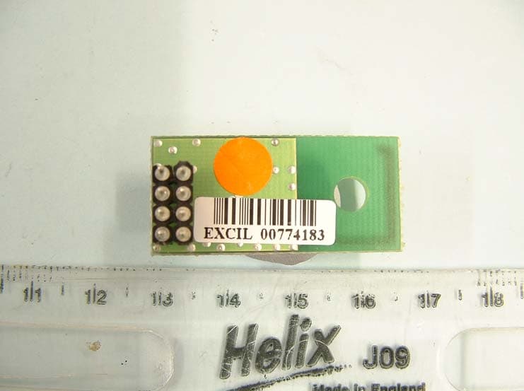
Click to zoom
Application Details
- Equipment Class
- DXT - Part 15 Low Power Transceiver, Rx Verified
- Date of Grant
- Sep 08, 2007
- Application Purpose
- Original Equipment
- Date of Application
- Sep 08, 2007
- Equipment Note
- 2.4GHz Two Way Radio Module
- Frequency Range
- 2476.90000000 - 2478.00000000
- Company
- Pretorian Technologies Ltd
- Country
- United Kingdom
Documents & Files
Document Text
Text extracted from the exhibit documents filed with the FCC. Open a document above to read the original.
Users Manual
Pairing TroubleshootingIf your OPTIMAX unit does not operate correctly, please use the following guide to determine the cause. If, after following this guide,your unit still does not operate, please contact your supplier beforereturning it: Symptom WarrantyYour OPTIMAX is warranted for 24 months from date of purchase against defects in manufacture or component failure. The unit isdesigned for domestic, educational, commercial and light industrialapplications. Use outside these areas will invalidate the warranty.Unauthorised repair or modification, mechanical abuse, immersionin any liquid or connection to any equipment other than a host computer will invalidate the warranty. Your OPTIMAX uses a unique addressing system to ensure that there is no interference from neighbouring units. The Trackball transmitsits data along with an address, and the Receiver unit only respondsto that address.To function correctly, both the Trackball and Receiver unit must use thesame address. The process of negotiating an address is called 'Pairing'and once learned, both the Trackball and Receiver units will retain theinformation even when powered off or when changing the battery.Your OPTIMAX is supplied already paired but it may occasionally be necessary to go through the process again- for instance if a newReceiver is to be used with an existing Trackball unit or in theunlikely event that one half 'forgets' the address.To Pair the units, use the following procedure:1. Remove the battery compartment cover. 2. Place the Trackball within one metre (three feet) of the Receiver unit. 3. Press the button on the underside of the Receiver unit. The LED should flash. 4. Within 10 seconds, briefly press the button inside the battery compartment. It is not necessary to spin the ball. 5. After a short period the LED should light steadily for 5 seconds and cursor operation should resume. Replace the battery compartment cover. 6. If the LED stops flashing after around 15 seconds and does not light steadily, repeat the process from (3). If it is still not successful, please refer to the Troubleshooting section. Possible cause/ Remedy No cursor movement-LED remains lit -Units are not Paired. Follow procedure in Pairing section. No cursor movement-LED is not lit. -Check USB or PS2 connection to computer.-Units may not be correctly Paired. Follow procedure in Pairing section. Cursor movement iserratic or sporadic. -Battery may be flat- replace.-Place Receiver unit away from metal objects and in view of Trackball operating area. -Out of range. Move Trackball closer to Receiver. -Interference from other radio equipment. Change channels by rebooting computer from cold. Units will not Pair- LEDis extinguished after 15seconds and cursordoes not move. -Ensure that Trackball is held within one metre (one yard) of Receiver while Pairing. -Check battery- replace if flat. OPTIMAX is the very first, wireless trackball specifically designed for users with motor skill difficulties.With an operating range in excess of 10 metres OPTIMAX is ideally suited for use in team/group sessions, or classroomsettings, to ensure the participation of all.Lightweight and robustly constructed with no mechanicalwearing parts, OPTIMAX can be used as either a desktop or hand-held unit.Optical technology ensures precise cursor control and silky-smooth ball movement, and the bi-directional radio link provides interference free operation. Product Description Optimax Unit 37 Corringham Road Industrial Estate Gainsborough Lincolnshire DN21 1QB United Kingdom Tel +44 (0) 1427 678990 Fax +44 (0) 1427 678992 www.pretorianuk.com leaflet 21/3/07 11:47 am Page 1 • State of the art radio link with an interference free operating range exceeding 10 metres. • Uses 2.4GHz global, licence-free ISM radio band.• Receiver unit includes two additional sockets.• Durable optical technology with no mechanical wearing parts. • Precise tracking and cursor control.• Large free-running ball requiring only the lightest touch.• Silky-smooth ball movement.• Robust, lightweight, construction.• Low profile providing a natural hand rest for comfortable operation. • Left/Right and Drag Lock buttons.• Colour coded buttons mounted sub-flush to prevent accidental operation. • Trackball sockets to operate Left/Right click buttons from remote switches. • Easy 'plug and play' installation (no additional drivers required). • Auto detecting PS2 and USB protocols.• PC and Mac compatible.• Typical 6 months battery life.Features Compatibility OPTIMAX works with PS2 and USB compatible computers including the majority of Personal Computers (PCs) and AppleMacintosh computers. Installation Ensure your computer is fully turned-off and not just insleep mode.Locate the relevant PS2 or USB socket on your computerand plug-in your OPTIMAX Receiver unit (if you are using the PS2 socket on your computer you will need the USB/PS2adaptor supplied).To optimise the range of the radio link, do not place theReceiver unit behind your computer or close to large metalobjects or sources of interference such as wireless networkhubs, cellular telephones etc.1. Invert the Trackball unit and remove the battery compartment cover using a screwdriver. 2. Connect a good quality 9-Volt PP3/6F-22 (or equivalent) battery (not supplied) to the battery connector. Alkaline batteries will give best battery life. Do not replace thebattery compartment cover at this stage. 3. Turn on the computer and allow it to fully boot up. Check that the LED on the rear of the Receiver unit lights for a few seconds and is then extinguished. If it remains lit, refer to the 'Pairing' section. 4. Move the Trackball to check for cursor movement and then replace the battery compartment cover. Your OPTIMAX is now ready for use. If there is no cursor movement, refer to the Troubleshooting section. MaintenanceYour OPTIMAX has no user serviceable parts. If repair is necessary the unit should be returned to Pretorian Technologies or an authorised Distributor. Unpac…
Text truncated - open the document above for the full version.
Cover Letter(s)
Federal Communications CommissionFCC 07-56 Before the Federal Communications Commission Washington, D.C. 20554 In the Matter of Modifications of Parts 2 and 15 of the Commission’s Rules for unlicensed devices and equipment approval ) ) ) ) ) ET Docket No. 03-201 SECOND REPORT AND ORDER Adopted: April 17, 2007 Released: April 23, 2007 By the Commission: I.INTRODUCTION 1.By this action, we amend our rules to providefor more efficient equipment authorization of both existing modular transmitter devices and emerging partitioned (or “split”)modular transmitter devices. These rule changeswill benefit manufacturers by allowinggreater flexibility incertifying equipmentandprovidingrelief from the need to obtain a new equipment authorization each time the same transmitter is installed in a different final product. Therule changes will also enable manufacturers to develop more flexible and more advanced unlicensed transmitter technologies.We further find that modular transmitter devices authorized in accordance with the revised equipment authorization procedures will not pose any increased risk of interference to other radio operations. II.BACKGROUND 2.Part 15 of the Commission’s rules governs the operation of unlicensed radio-frequency devices. As a general condition of operation, Part 15 devices may not cause harmful interference to authorized radio services and must accept any interference that they receive. 1 In recent years, there has been a significant increase in the number and types of devices operating under the Part 15 rules. Examples of common Part 15 devices include cordless phones, computers, wireless baby monitors, and garage door openers. Such devices are widely used in everyday consumer functions. Moreover, the rapid growthof devices that followindustrystandards, such as IEEE 802.11 and Bluetooth, promise to further increase both the number and variety of devices that will operate on an unlicensed basis. Overall, the Part 15 rules have been highly successful in fostering the development of new unlicensed devices while protecting authorized users of the radio spectrum from harmful interference. Millions of Part 15 devices operate within the current rules without any significant interference issues. 3.In recent years, manufacturers have developed Part 15 transmittermodules (or “single” modules) that can be incorporated into many different devices. These modules generally consist of a completely self-contained radio-frequency transmitter (transmission system) missing only an input signal source and a powersource to make it functional. Once the modules are authorized by the Commission under itscertification procedure, they may be incorporated into a number of host devices such as personal computers (PCs)or personal digital assistants (PDAs), which have been separately authorized. 2 The 1 47 C.F.R. § 15.5. 2 The Commission’s equipment certification procedure is set forth in Sections 2.907, 2.927, 2.931, and Sections 2.1031 through 2.1060, 47 C.F.R. §§ 2.907, 2.927, 2.931 and 2.1031-2.1060. Federal Communications CommissionFCC 07-56 2 completed product generally is not subject to requirements for further certification by the Commission. Therefore, modular transmitters save manufacturers the time and any related expenses that would be incurred if a new equipment authorization were needed for the same transmitter when it is installed in a new device. 4.This efficiency is a result of the June 26, 2000 Public Noticewhich the Commission released in response to manufacturers’ request for guidance about the conditions under which approvals for Part 15 modular transmitters may be granted. 3 The Public Noticedetailed eight criteria that must be met in order for the Commission to grant certification for modular transmitters. The Public Noticeonly addressed deviceswhere all of the radio frequency components were contained completely within the module itself. 5.A new class of “split” modular devices is now under development. 4 These transmitters consist of two basic components: the “radio front end” or radio elements and the “firmware” or hardware on which the software that controls the radio operation resides. The radio front end and firmware can each be self-contained units. In split modular devices the radio front end is generally a stand-alone unit, while the firmware may either be a stand-alone unit or may be collocated within a device on a host system. A further partitioning is also possible by removing the local oscillator and tuning capacitors of the antenna from the radio front end. The separation of modular devices into these components will provide manufacturers the flexibility to design a larger variety of modular systems by mixing and matching individual components. 6.On September 10, 2003, the Commission adopted a Notice of Proposed Rulemaking(Notice) inwhich it, inter alia,proposed to clarify the equipment authorization requirements for modular transmitters. 5 Sixteen parties filed comments in response to the Notice’sproposals forPart 15unlicensed transmitter module approvals.These parties arelisted in Appendix C. III.DISCUSSION 7.In this Second Report and Orderwe codify the Public Noticerequirements for approving modular transmitters, with certain modifications. We also adoptrequirements for the approval of split moduletransmitters, including a requirement that only parts of a split modulethat have been approved in a single application for equipment authorization may operatetogether. Further, we allow manufacturers the flexibility to demonstrate alternative methods in the application for equipment authorization to ensure that amodular transmitter will meetall the applicable Part 15 requirements under the operating conditions in which itwill be used. We find that the increased flexibility adopted herein will facilitatethe approval processfor modular transmittersandprovide relief from the need to obtain a new equipment authorization each time the same transmitter is installed in a diffe…
Text truncated - open the document above for the full version.
External Photos
Radio Module Track Side Radio Module Component Side
ID Label/Location Info
Pretorian Technol ogies Lt d. VKLE080025 RADIO MODULE Sample label: Photo of label affixed to module: Label material: Polypropylene Label marking: Thermal Label adhesive: Permanent acrylic adhesive
Internal Photos
Radio Module Track Side Radio Module Component Side
Test Report
REPORT ON THE CERTIFICATION TESTING OF A PRETORIAN TECHNOLOGIES Ltd 2.4GHz 2-WAY RADIO MODULE E080025 WITH RESPECT TO THE FCC RULES CFR 47, PART 15.249 May 2007 INTENTIONAL RADIATOR SPECIFICATION TEST REPORT NO: RU1356/7975 COPY NO: 2 ISSUE NO: 1 FCC ID: VKLE080025 REPORT ON THE CERTIFICATION TESTING OF A PRETORIAN TECHNOLOGIES Ltd 2.4GHz 2-WAY RADIO MODULE E080025 WITH RESPECT TO THE FCC RULES CFR 47, PART 15.249 May 2007 INTENTIONAL RADIATOR SPECIFICATION TEST DATE: 9 th – 12 th July 2007 TESTED BY: D WINSTANLEY APPROVED BY: J CHARTERS RADIO SECTION LEADER DATE: 31 st August 2007 Distribution: Copy Nos: 1. Pretorian Technologies Ltd 2. FCC EVALUATION LABORATORIES 3. TRL Compliance Ltd THIS DOCUMENT MAY BE REPRODUCED ONLY IN ITS ENTIRETY AND WITHOUT CHANGE RF335U iss03B RU1356/7975 Page 3 of 37 CONTENTS PAGE CERTIFICATE OF CONFORMITY & COMPLIANCE 4 APPLICANT’S SUMMARY 5 EQUIPMENT TEST CONDITIONS 6 TESTS REQUIRED 6 TEST RESULTS 7- 16 ANNEX PHOTOGRAPHS A PHOTOGRAPH No. 1: Test setup PHOTOGRAPH No. 2: Radio Module Track Side PHOTOGRAPH No. 3: Radio Module Component Side APPLICANT’S SUBMISSION OF DOCUMENTATION LIST B MEASUREMENT UNCERTAINTY C TEST EQUIPMENT CALIBRATION D BAND OCCUPANCY PLOT E EMISSIONS GRAPH(S) F AC POWERLINE CONDUCTION GRAPH(S) G Notes: 1. Component failure during test YES NO [ ] [X] 2. If Yes, details of failure: 3. The facilities used for the testing of the product contain in this report are FCC Listed. 4. The contents of the attached applicants declarations and other supplied information are not covered by the scope of this laboratory’s UKAS or FCC accreditations’ and is provided in good faith. RF335U iss03B RU1356/7975 FCC IDENTITY: VKLE080025 PURPOSE OF TEST: Certification TEST SPECIFICATION: FCC RULES CFR 47, Part 15.249 May 2007 TEST RESULT: Compliant to Specification EQUIPMENT UNDER TEST: 2.4GHz 2-Way Radio Module E080025 ITU: EMISSION CODE: 1M125F1D EQUIPMENT TYPE: Radio Transceiver Module PRODUCT USE: Telemetry CARRIER EMISSION: 43.7 mV/m @3m ANTENNA TYPE: Integral ALTERNATIVE ANTENNA: Not Applicable BAND OF OPERATION: 2400 MHz – 2483.5 MHz NUMBER OF CHANNELS: 16 FREQUENCY GENERATION: SAW Resonator [ ] Crystal [X] Synthesiser [ ] MODULATION METHOD: Amplitude [ ] Digital [X] Angle [ ] POWER SOURCE(s): +3.3Vdc TEST DATE(s): 9 th – 12 th July 2007 ORDER No(s): 14879 APPLICANT: Pretorian Technologies Ltd ADDRESS: Unit 37 Corringham Road Industrial Estate Gainsborough Lincolnshire DN21 1QB TESTED BY: D WINSTANLEY APPROVED BY: J CHARTERS RADIO SECTION LEADER CERTIFICATE OF CONFORMITY & COMPLIANCE RF335U iss03B RU1356/7975 Page 5 of 37 APPLICANT’S SUMMARY EQUIPMENT UNDER TEST (EUT): 2.4GHz 2-Way Raio Module E080025 EQUIPMENT TYPE: Radio Transceiver Module PURPOSE OF TEST: Certification TEST SPECIFICATION(s): FCC RULES CFR 47, Part 15.249 May 2007 TEST RESULT: COMPLIANT Yes No [X] [ ] APPLICANT’S CATEGORY: MANUFACTURER IMPORTER DISTRIBUTOR TEST HOUSE AGENT [X] [ ] [ ] [ ] [ ] APPLICANT’S ORDER No(s): 14879 APPLICANT’S CONTACT PERSON(s): Mr D Gilbert E-mail address: [email protected] APPLICANT: Pretorian Technologies Ltd ADDRESS: Unit 37 Corringham Road Industrial Estate Gainsborough Lincolnshire DN21 1QB TEL: +44 (0) 1427 678990 FAX: +44 (0) 1427 678992 EUT(s) COUNTRY OF ORIGIN: United Kingdom TEST LABORATORY: TRL Compliance Ltd UKAS ACCREDITATION No: 0728 TEST DATE(s): 9 th – 12 th July 2007 TEST REPORT No: RU1356/7975 RF335U iss03B RU1356/7975 Page 6 of 37 EQUIPMENT TEST / EXAMINATIONS REQUIRED 1. TEST/EXAMINATION RULE PART DETECTOR APPLICABILITY Intentional Emission Frequency: 15.249(a) Quasi Peak YES Intentional Emission Field Strength: 15.249(a) Quasi Peak YES Intentional Emission Band Occupancy: 15.215 Peak YES Intentional Emission ERP (mW): N/A - NO Spurious Emissions – Conducted: 15.207 - NO Spurious Emissions – Radiated <1000MHz: 15.209 Quasi Peak YES Spurious Emissions – Radiated >1000MHz: 15.209 15.249(a) Average YES Maximum Frequency of Search: 15.33 - YES Antenna Arrangements Integral: 15.203 - YES Antenna Arrangements External Connector: 15.204 - YES Restricted Bands 15.205 - YES Extrapolation Factor 15.31(f) - YES 2. Product Use: Telemtry 3. Emission Designator: 1M125F1D 4. Duty Cycle: <100% 5. Transmitter bit or pulse rate and level: 2Mbps 6. Temperatures: Ambient (Tnom) 17 o C 7. Supply Voltages: Vnom +3.3Vdc Note: Vnom voltages are as stated above unless otherwise shown on the test report page Single channel [ ] Two channel [ ] 8. Equipment Category: Multi-channel [X] Narrowband [ ] Wideband [X] 9. Channel spacing: RF335U iss03B RU1356/7975 Page 7 of 37 TRANSMITTER TESTS TRANSMITTER SPURIOUS EMISSIONS – RADIATED – PART 15.209 Ambient temperature = 17 o C(<1GHz) 3m measurements <1GHz [X] Relative humidity = 62% (<1GHz), 3m measurements >1GHz [X] Conditions = Open Area Test Site (OATS) 3m extrapolated from 1m [ ] Supply voltage = +3.3Vdc Bottom Channel FREQ. (MHz) MEAS Rx (dBμV) CABLE LOSS (dB) ANT FACT. (dB/m) PRE AMP (dB) FIELD ST’GH (dBμV/m) EXTRAP FACT (dB) FIELD ST’GH (μV/m) LIMIT (μV/m) 0.009MHz - 0.49MHz Note 9. 0.49MHz - 1.705MHz Note 9. 1.705MHz - 30MHz Note 9. 30MHz - 88MHz Note 9. 88MHz - 216MHz Note 9. 216MHz - 960MHz Note 9. 960MHz - 1GHz Note 9. 1GHz - 25GHz 2400.000 2747.955 4804.448 7207.282 46.03 43.45 35.50 34.97 1.1 1.3 2.4 3.0 28.8 29.9 33.6 37.4 36.3 36.3 36.5 36.3 39.63 38.35 35.00 39.07 - - - - 95.83 82.70 56.23 89.84 500 500 500 500 0.009 MHz to 0.49 MHz 2400/f(kHz) μV/m @ 300m 0.49 MHz to 1.705 MHz 24000/f(kHz) μV/m @ 30m 1.705MHz to 30MHz 30μV/m @ 30m 30MHz to 88MHz 100μV/m @ 3m 88MHz to 216MHz 150μV/m @ 3m 216MHz to 960MHz 200μV/m @ 3m 960MHz to 1GHz 500μV/m @ 3m Limits 1GHz to 25GHz 500μV/m @ 3m RF335U iss03B RU1356/7975 Page 8 of 37 Middle Channel FREQ. (MHz) MEAS Rx (dBμV) CABLE LOSS (dB) ANT FACT. (dB/m) PRE AMP (dB) FIELD ST’GH (dBμV/m) EXTRAP FACT (dB) FIELD ST’GH (μV/m) LIMIT (μV/m) 0.009MHz - 0.49MHz Note 9. 0.49MHz - 1.705MHz Note 9. 1.705MHz - 30MHz Note 9. 30MHz - 88MHz Note 9. 88MHz - 216MHz Note 9. 216MHz - 960MH…
Text truncated - open the document above for the full version.
Test Setup Photos
Test Setup OATS Test Setup OATS Close Up Test Setup Powerline Conduction
Contact Information
Applicant
David Peter Gilbert(Technical Director)
Test Firm
TRL Compliance LtdJohn Charters
Technical Specifications
| # | Rule Parts | Frequency Range | Power Output |
|---|---|---|---|
| 3 | 15C | 2.48 GHz - 2.48 GHz | - |