VLE15054-PPLMini Crazy Dancer/Jeep Stunt Truck Mini R/C
Asian Express Holdings Limited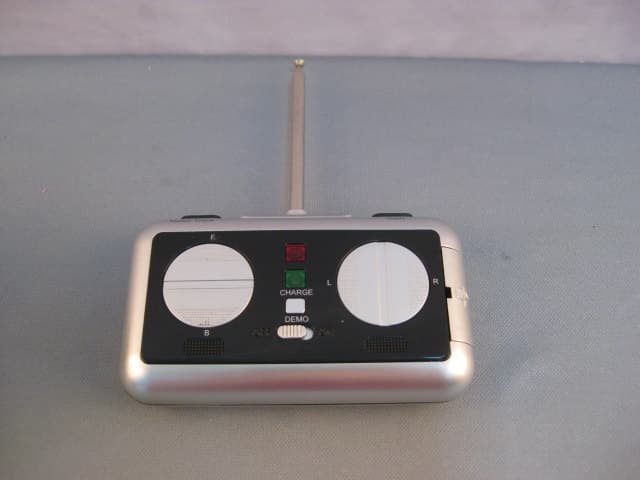
Click to zoom
Application Details
- Equipment Class
- DXX - Part 15 Low Power Communication Device Transmitter
- Date of Grant
- Jun 27, 2010
- Application Purpose
- Original Equipment
- Date of Application
- Jun 27, 2010
- Equipment Note
- Mini Crazy Dancer/Jeep Stunt Truck Mini R/C
- Frequency Range
- 27.14500000 - 27.14500000
- Country
- Hong Kong
Documents & Files
Document Text
Text extracted from the exhibit documents filed with the FCC. Open a document above to read the original.
Users Manual
NOTE: READ BEFORE USE Please read this instruction manual prior to using your Crazy Dancer TM Stunt Truck in order to familiarize yourself with the product functions. Be sure to follow all battery warnings and charging instructions to ensure proper and safe operation of your product. CHARGING YOUR CRAZY DANCER ™ RC STUNT TRUCK Be sure to properly charge the battery pack before play. Proper charging will ensure maximum battery life and hours of exciting play with your Crazy Dancer ™ RC Stunt Truck. Battery Charging Diagram Diagram A NOTE: Be sure to use the included battery charger to charge the included rechargeable battery otherwise damage to your product may occur. 1. Connect the battery-charging adapter to the connector on the rechargeable battery. 2. Plug the charger into a standard 110V electrical outlet that is properly installed and grounded. 3. Before using your vehicle for the first time, charge the battery for 5 hours. On subsequent charges, allow the battery to charge for 3 hours. 4. To disconnect the battery pack from the charger, first unplug the wall adapter, then disconnect the adapter from the battery by pressing the battery release button on the plastic connector. NOTE: Battery life depends on how the vehicle is used. The Crazy Dancer TM RC Stunt Truck operates for approximately 20 minutes per charge. The 8.4V nickel-cadmium battery should be charged with adult supervision. BATTERY WARNINGS • Do not mix alkaline, standard (carbon-zinc) and rechargeable batteries (Nickel Metal Hydride). • Do not mix old and new batteries. • Do not attempt to recharge non-rechargeable batteries. • Rechargeable batteries are to be removed from the product before being charged (if removable). • Rechargeable batteries are only to be charged under adult supervision. • Exhausted batteries should be removed immediately and must be recycled or disposed of properly according to state or local government ordinances and regulations. • Do not allow conductive materials such as rings, bracelets, or keys to touch the batteries, otherwise a short circuit may cause the batteries and/or the conductive material to overheat and cause burns. • Only batteries of the same or equivalent type as recommended are to be used. • Batteries are to be inserted with the correct polarity (refer to included diagrams). • Do not dispose batteries in a fire as batteries may leak or explode. 8.4V BATTERY AC CHARGER ADAPTER WALL POWER ON/OFF BATTERY COMPARTMENT TRUCK DIAGRAM REMOTE CONTROL DIAGRAM BASIC CONTROL FUNCTIONS Turn on the power switch on the bottom of the vehicle first, and then turn on the power switch on the back of the controller. Press the START/STOP button to start your vehicle. Press the upper part of the left control pad to move the vehicle forward. Press the lower part of the left control pad to move the vehicle backward. Press the left part of the right control pad to turn the vehicle left. Press the right part of the right control pad to turn the vehicle right. To rotate the vehicle left, press the upper part of the left control pad while pressing the left part of the right control pad. To rotate the vehicle right, press the upper part of the left control pad while pressing the right part of the right control pad. Normal control distance is approximately 80 feet in a non-interference area. OPERATING YOUR CRAZY DANCER ™ RC STUNT TRUCK 1. Charge the included 8.4V rechargeable battery as described in Battery Charging Diagram on page 1. 2. Insert the rechargeable battery into the battery compartment on the backside of the vehicle and properly close the battery compartment door. See Diagram A on page 1. 3. Insert one 9V battery (not included) into the bottom of the wireless controller. NOTE: the battery compartment is designed so that the 9V battery must be placed in the proper direction or it will not fit correctly. Please study the diagram inside the battery compartment and do not force the battery. Hint: If having difficulty, try turning the battery in a different direction. 4. Install the included antenna into the top of the wireless controller. When installing the antenna, turn or “screw” the antenna clockwise until it stops moving. Never force the antenna once it stops turning. Hint: Remember to extend the antenna for maximum performance and control distance. 5. Turn on the wireless controller by placing the power switch on the backside of the remote to the ON position. You will notice a red LED light turn on in the front of the controller. 6. Turn on the vehicle by placing the “ON/OFF” switch at the bottom of the vehicle to the “ON” position, you will hear a “beep” sound and see the running lights, light up. The lights will always stay on until you turn the power switch at the bottom of the vehicle to the “OFF” position. 7. Press the START/STOP button on the upper right edge of the remote control unit to start the vehicle. You can begin to play after you hear the vehicle “ignition start sound”. 8. Operate the vehicle and do crazy stunts by using the left/right and forward/back control pads. 9. Turning off your vehicle: Make sure to first turn off your wireless controller, then turn the switch on bottom of the vehicle to the “off” position. When your vehicle is powered off, there will be no more flashing lights. NOTE: THE VEHICLE WILL NOT OPERATE UNLESS THE START/STOP BUTTON IS PRESSED. OTHER BUTTON FUNCTIONS 1. HORN: Tap the START/STOP button to sound the vehicle’s built-in horn. 2. PLAY MUSIC: Press the MUSIC button on the upper left edge of the remote control to listen to the built-in sound tracks. Press the MUSIC button again to cycle through the 3 sound tracks. 3. TURN OFF MUSIC: While playing a music track, tap the START/STOP button to turn off the music. 4. DEMO MODE: To familiarize yourself with various functions of the vehicle, press the DEMO button to watch the vehicle dance by itself along to music! Press the DEMO button again to watch the vehicle dance to the next included sound track. There a…
Text truncated - open the document above for the full version.
Cover Letter(s)
SCS-F18: Project and Product Certification Representative Authorization Letter Page 1 of 2 Rev 2.0 2206 Ringwood Avenue San Jose, CA 95131 Tel: 408-526-1188 Fax: 408-526-1088 Email: [email protected] Project and Product Certification Representative Authorization Letter Revision History Reason for Amendment (current / obsolete) From To Approved Date Initial Release (current) 1.0 1.0 Nov-14-2006 Revised wording (current) 1.0 2.0 Sept–25-2007
Cover Letter(s)
SCS-F19: Confidentiality Request Letter Page 1 of 2 Rev 2.0 2206 Ringwood Avenue San Jose, CA 95131 Tel: 408-526-1188 Fax: 408-526-1088 Email: [email protected] Confidentiality Request Letter Revision History Reason for Amendment (current / obsolete) From To Approved Date Initial Release (current) 1.0 1.0 Nov-14-2006 Adding CFR 2.459 1.0 2.0 August – 11 - 2008
External Photos
1 Photographs - EUT Construction Details
Test Report
Report No.: SZEMO10050245201 Page: 1 of 9 Authorized Signature: Jack Zhang Laboratory Manager The manufacturer should ensure that all products in series production are in conformity with the product sample detailed in this report. If the product in this report is used in any configuration other than that detailed in the report, the manufacturer must ensure the new system complies with all relevant standards. Any mention of SGS International Electrical Approvals or testing done by SGS International Electrical Approvals in connection with, distribution or use of the product described in this report must be approved by SGS International Electrical Approvals in writing. The report must not be used by the client to claim product certification, approval, or endorsement by NVLAP, NIST, or any agency of the federal government. All test results in this report can be traceable to National or International Standards. “This document is issued by the Company subject to its General Conditions of Service printed overleaf, available on request or accessible at www.sgs.com/terms_and_conditions.htm and, for electronic format documents, subject to Terms and Conditions for Electronic Documents at www.sgs.com/terms_e-document.htm. Attention is drawn to the limitation of liability, indemnification and jurisdiction issues defined therein. Any holder of this document is advised that information contained hereon reflects the Company’s findings at the time of its intervention only and within the limits of Client’s instructions, if any. The Company’s sole responsibility is to its Client and this document does not exonerate parties to a transaction from exercising all their rights and obligations under the transaction documents. This document cannot be reproduced except in full, without prior written approval of the Company. Any unauthorized alteration, forgery or falsification of the content or appearance of this document is unlawful and offenders may be prosecuted to the fullest extent of the law. Unless otherwise stated the results shown in this test report refer only to the sample(s) tested and such sample(s) are retained for 90 days only.” SGS-CSTC Standards Technical Services Ltd. No. 1 Workshop, M-10, Middle section, Science & Technology Park, Shenzhen, Guangdong, China 518057 Telephone: +86 (0) 755 2601 2053 Fax: +86 (0) 755 2671 0594 Email: [email protected] FCC REPORT Application No. : SZEMO100502452ET(SGS SZ No.: SZTYR100500543EM) Applicant: Asian Express Holding Ltd Product Name: Mini Crazy Dancer/Jeep Stunt Truck Mini Model Name: 15054-PPL-B-ASM Operation Frequency: 27.145MHz FCC ID: VLE15054-PPL Standards: FCC PART 15, SUBPART C : 2008 Section 15.227 Date of Receipt 06 May 2010 Date of Test 07 May to 23 June 2010 Date of Issue 24 June 2010 Test Result : PASS * * In the configuration tested, the EUT complied with the standards specified above. “This document is issued by the Company subject to its General Conditions of Service printed overleaf, available on request or accessible at www.sgs.com/terms_and_conditions.htm and, for electronic format documents, subject to Terms and Conditions for Electronic Documents at www.sgs.com/terms_e-document.htm. Attention is drawn to the limitation of liability, indemnification and jurisdiction issues defined therein. Any holder of this document is advised that information contained hereon reflects the Company’s findings at the time of its intervention only and within the limits of Client’s instructions, if any. The Company’s sole responsibility is to its Client and this document does not exonerate parties to a transaction from exercising all their rights and obligations under the transaction documents. This document cannot be reproduced except in full, without prior written approval of the Company. Any unauthorized alteration, forgery or falsification of the content or appearance of this document is unlawful and offenders may be prosecuted to the fullest extent of the law. Unless otherwise stated the results shown in this test report refer only to the sample(s) tested and such sample(s) are retained for 90 days only.” Report No.: SZEMO10050245201 Page: 2 of 9 SGS-CSTC Standards Technical Services Ltd. 2 Contents Page 1 COVER PAGE 1 2 CONTENTS.............................................................................................................................................................. 2 3 TEST SUMMARY.................................................................................................................................................... 3 4 GENERAL INFORMATION.................................................................................................................................... 4 4.1 CLIENT INFORMATION............................................................................................................................................. 4 4.2 GENERAL DESCRIPTION OF E.U.T. .......................................................................................................................... 4 4.3 E.U.T. ENVIRONMENT AND TEST MODES................................................................................................................ 4 4.4 TEST LOCATION...................................................................................................................................................... 5 4.5 OTHER INFORMATION REQUESTED BY THE CUSTOMER........................................................................................... 5 4.6 TEST FACILITY........................................................................................................................................................ 5 4.7 TEST INSTRUMENTS LIST........................................................................................................................................ 6 5 TEST RESULT & MEASUREMENT DATA......................................................................................................... …
Text truncated - open the document above for the full version.
Test Setup Photos
1 Photographs - Test Setup Radiated Emission
Contact Information
Applicant
Nancy Chen(QA Manager)
Test Firm
SGS-CSTC Standards Technical Services Co.,Ltd.June Zhang
Technical Specifications
| # | Rule Parts | Frequency Range | Power Output |
|---|---|---|---|
| 1 | 15C | 27.145 MHz - 27.145 MHz | - |
Other Applications from Asian Express Holdings Limited
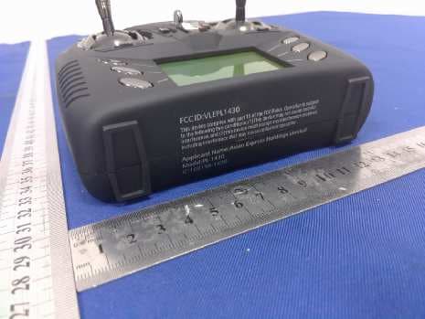
VLEPL1431
Dec 06, 2015Cloud Rider Drone
Equipment Class
DXX - Part 15 Low Power Communication Device Transmitter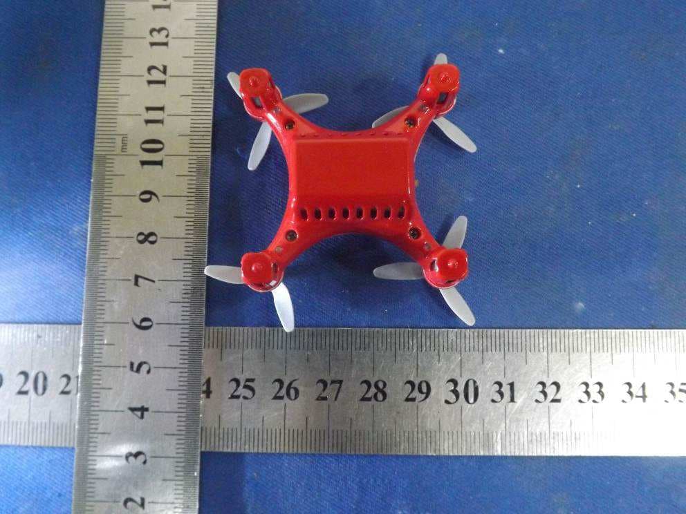
VLE1392-R
Nov 16, 2015Air Micro Drone
Equipment Class
DXX - Part 15 Low Power Communication Device Transmitter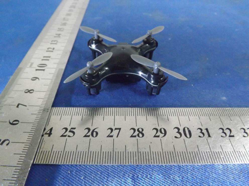
VLE1470R
Nov 16, 2015ZIP Micro Drone
Equipment Class
DXX - Part 15 Low Power Communication Device Transmitter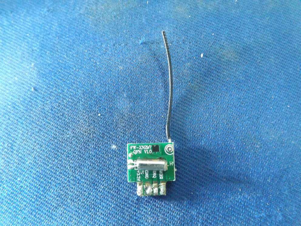
VLE1392
Nov 16, 2015Air Micro Drone
Equipment Class
DXX - Part 15 Low Power Communication Device Transmitter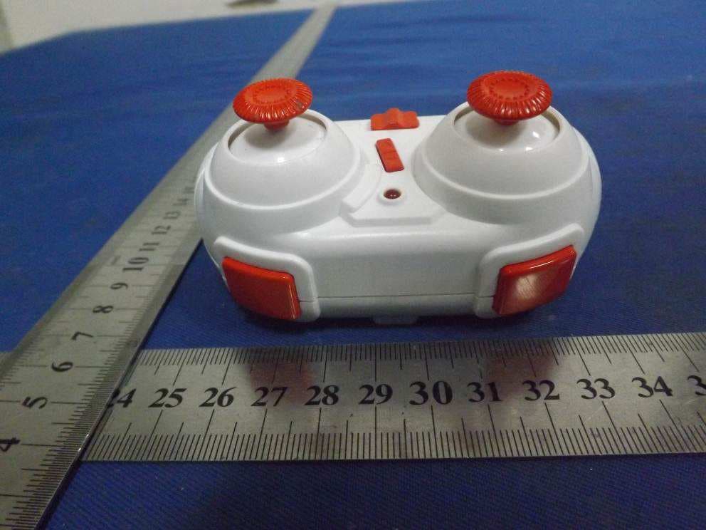
VLE1470
Nov 16, 2015Zip Micro Drone
Equipment Class
DXX - Part 15 Low Power Communication Device Transmitter