VLEPL1180-TZEPHYRUS/QUADCOPTER
Asian Express Holdings Limited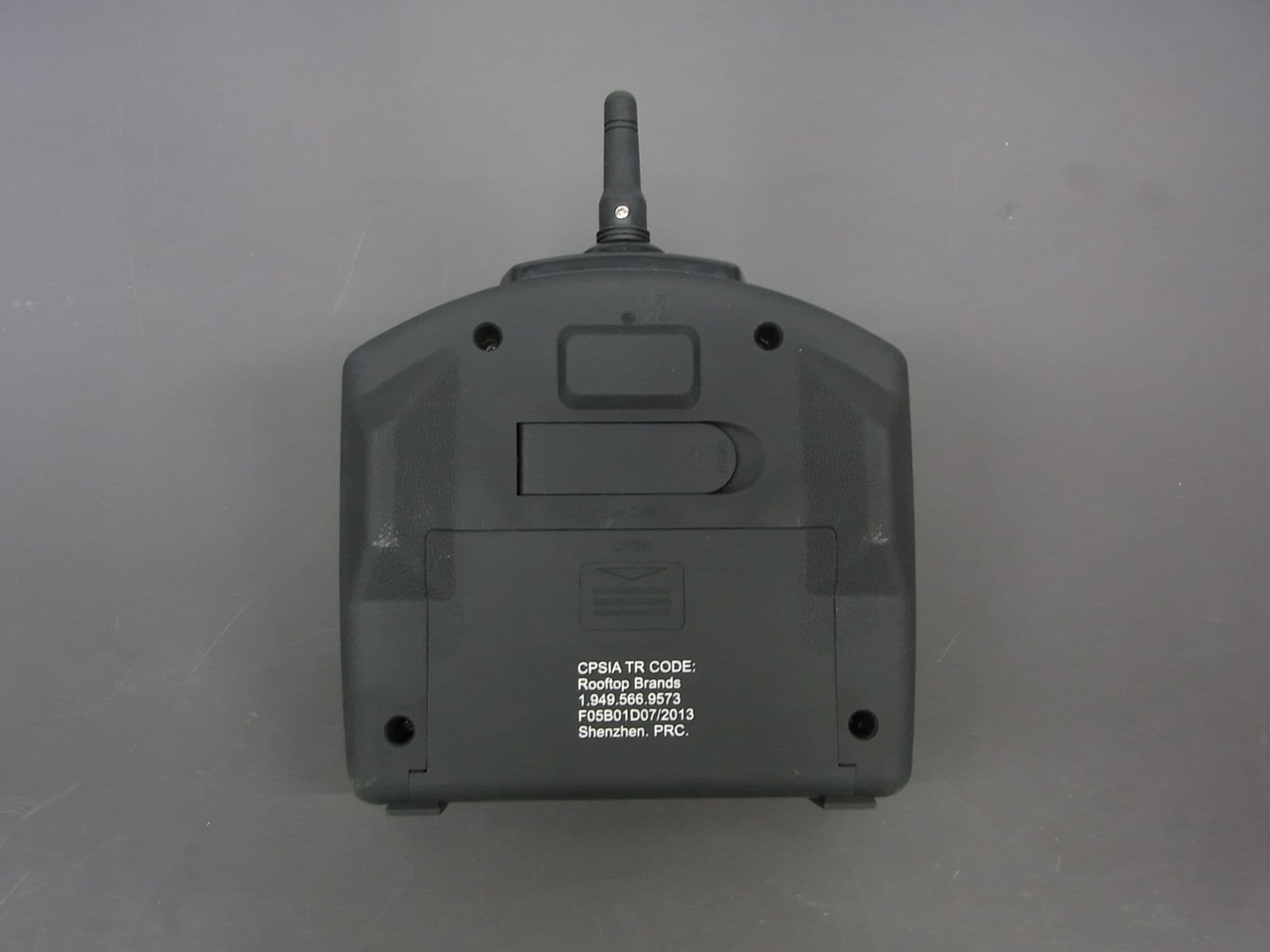
Click to zoom
Application Details
- Equipment Class
- DXX - Part 15 Low Power Communication Device Transmitter
- Date of Grant
- Oct 20, 2013
- Application Purpose
- Original Equipment
- Date of Application
- Oct 20, 2013
- Equipment Note
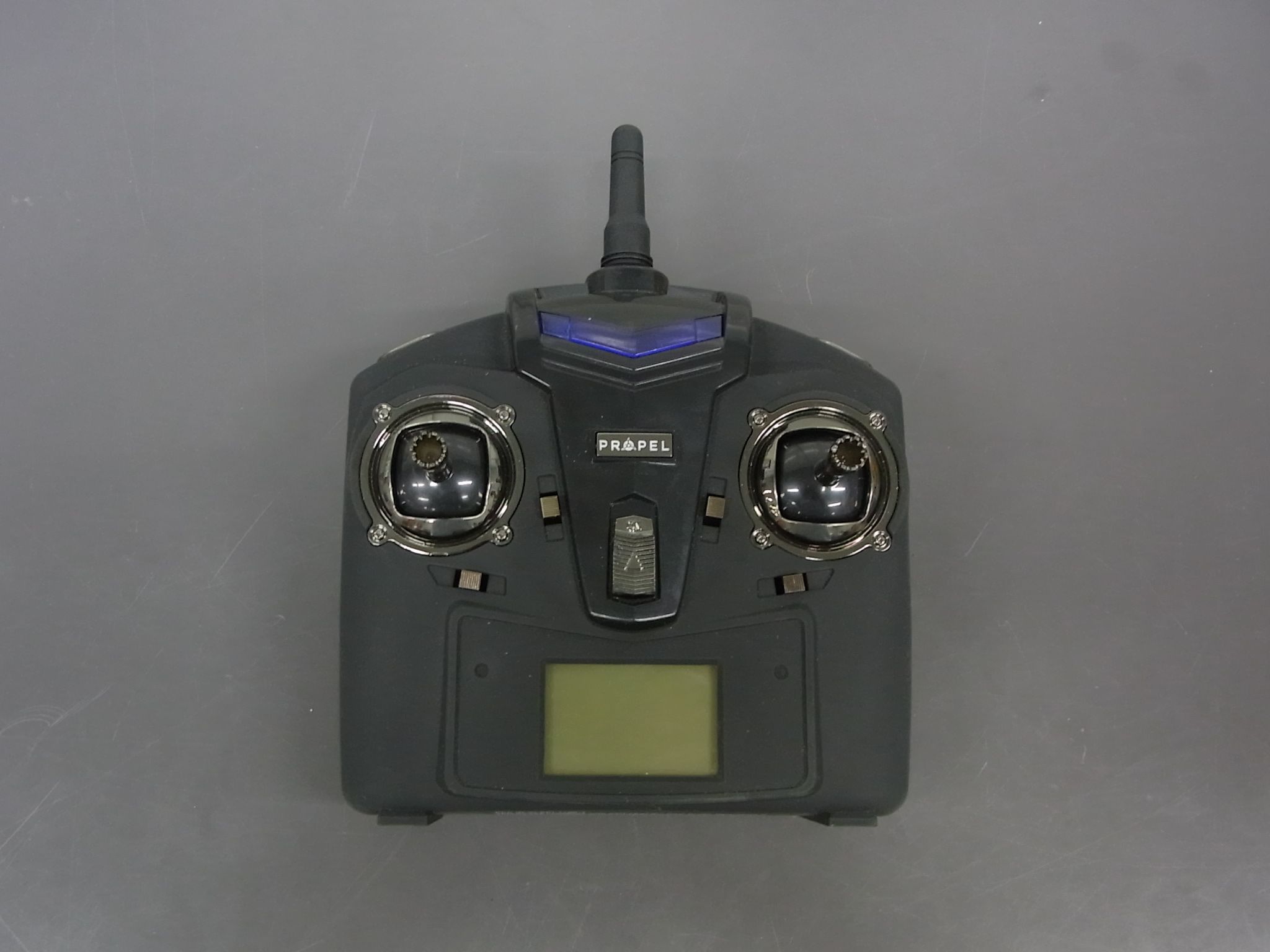
- ZEPHYRUS/QUADCOPTER
- Frequency Range
- 2417.00000000 - 2458.00000000
- Country
- Hong Kong
Documents & Files
Document Text
Text extracted from the exhibit documents filed with the FCC. Open a document above to read the original.
Users Manual
WARNING: Never leave product charging unattended for extended periods of time. Always disconnect Quadrocopter from charger immediately after the Quadrocopter is fully charged. Please refer to enclosed safety instructions. INSTRUCTION BOOKLET Colors and styles may slightly vary. Made in China Conforms to safety requirements of ASTM, CPSIA and FCC. ©2013 Rooftop Brands™ All rights reserved Tel: + (1) 949-566-9573 • www.propelrc.com CHOKING HAZARD - Small parts. Not suitable for children under 3 years. WARNING! PACKAGE CONTAINS: 2.4G Wireless ControllerInstruction BookletQuadrocopter TM ZEPHYRUS 2.4GHz indoor & outdoor quadrocopter FCC Part 15 B Notice CAUTION: Changes or modifications not expressly approved by the party responsible for compliance could void the user’s authority to operate the equipment. NOTE: This equipment has been tested and found to comply with the limits for a Class B digital device, pursuant to Part 15 of the FCC Rules. These limits are designed to provide reasonable protection against harmful interference in a residential installation. This equipment generates, uses and can radiate radio frequency energy and, if not installed and used in accordance with the instructions, may cause harmful interference to radio communications. However, there is no guarantee that interference will not occur in a particular installation. If this equipment does cause harmful interference to radio or television reception, which can be determined by turning the equipment off and on, the user is encouraged to try to correct the interference by one or more of the following measures: • Reorient or relocate the receiving antenna. • Increase the separation between the equipment and receiver. • Connect the equipment into an outlet on a circuit different from that to which the receiver is connected. • Consult the dealer or experienced radio/TV technician for help. This device complies with Part 15 of the FCC Rules. Operation is subject to the following two conditions : (1) This device may not cause harmful interference, and (2) this device must accept any interference received, including interference that may cause undesired operation. 11 Thank you for purchasing the Zephyrus™ 2.4 G Indoor & Outdoor Quadrocopter. Please read this instruction booklet as it contains valuable information on how to properly fly and care for your Quadrocopter. FEATURES Built in 3 axis gyroscopic chip keeps the Zephyrus extremely stable in all conditions. 4 channel flight controls allow for incredible manoeuvrability including 360 ̊ aerial stunts! 5 speed settings for beginner to advanced quadrocopter pilots. LED directional lights makes the Zephyrus easy to follow. Replaceable Li-poly battery included. 200 foot range. REMOTE CONTROL BATTERY INSTALLATION 1. Slide the battery cover off of the remote control. 2. Install 6 “AA” alkaline batteries into the battery pack and then install the pack in the controller as shown in the diagram. 3. Replace the battery cover. QUADROCOPTER BATTERY INSTALLATION 1. Snap off the cover on the bottom of the quadrocopter(see diagram B). 2. Slide the battery in and connect the power cord as shown on diagram C. 3. Replace the bottom cover. CHARGING THE BATTERY 1. Connect the battery to the adaptor as shown (see illustration A). 2. Plug the charger into a wall outlet. The charger's charging indicator lights red to show that charging is in progress. 3. Average charging time is approximately 90-120 minutes. The Quadrocopter operates for approximately 6-8 minutes on full charge. 4. The charging indicator turns off when the battery is fully charged. Battery Compartment (6 “AA” batteries) TABLE OF CONTENTS Features............................................................................................................ 2 Remote Battery Installation..................................................................................... 2 Charging the Quadrocopter Battery.............................................................................. 2 Quadrocopter Battery Installation................................................................................ 2 Quadrocopter Diagram, Remote Diagram........................................................................ 3 Preparing For Flight...............................................................................................4 Syncing Your Quadrocopter........................................................................................4 Flying Tips........................................................................................................ 4 Turn Left / Right Trim............................................................................................. 5 Forward / Backward Trim........................................................................................ 5 Banking Left / Right Trim........................................................................................ 6 Throttle Sensitivity Trim.......................................................................................... 6 Speed Select button............................................................................................. 6 Flight Control...................................................................................................... 7 360 ̊ Stunt rolls.................................................................................................... 8 Troubleshooting.................................................................................................. 9 Battery Warnings, Care and Maintenance...................................................................... 9 FCC Part 15 B Notice............................................................................................ 11 Battery Cover A BC IMPORTANT: ALWAYS DISCONNECT WALL CHARGER AFTER CHARGING. NEVER LEAVE CHARGER CONNECTED TO QUADROCOPTER BATTERY OVERNIGHT OR FOR EXTENDED PERIODS OF TIME. Note: the adaptor should be periodically examined for conditions that may …
Text truncated - open the document above for the full version.
ID Label/Location Info
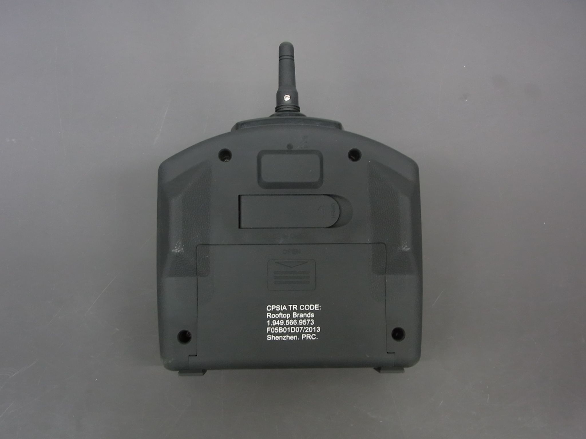
Transmitter: Remark: We will print the FCC ID on the transmitter by Pad Printing.
Test Report
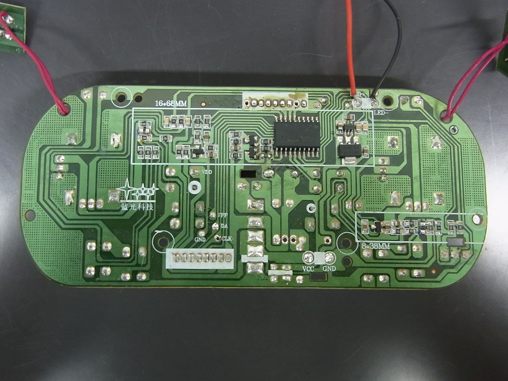
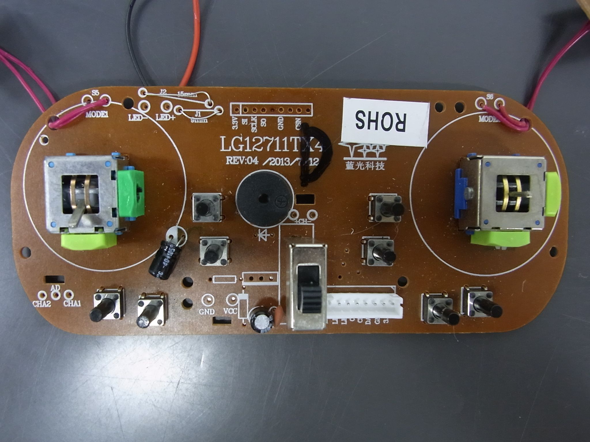
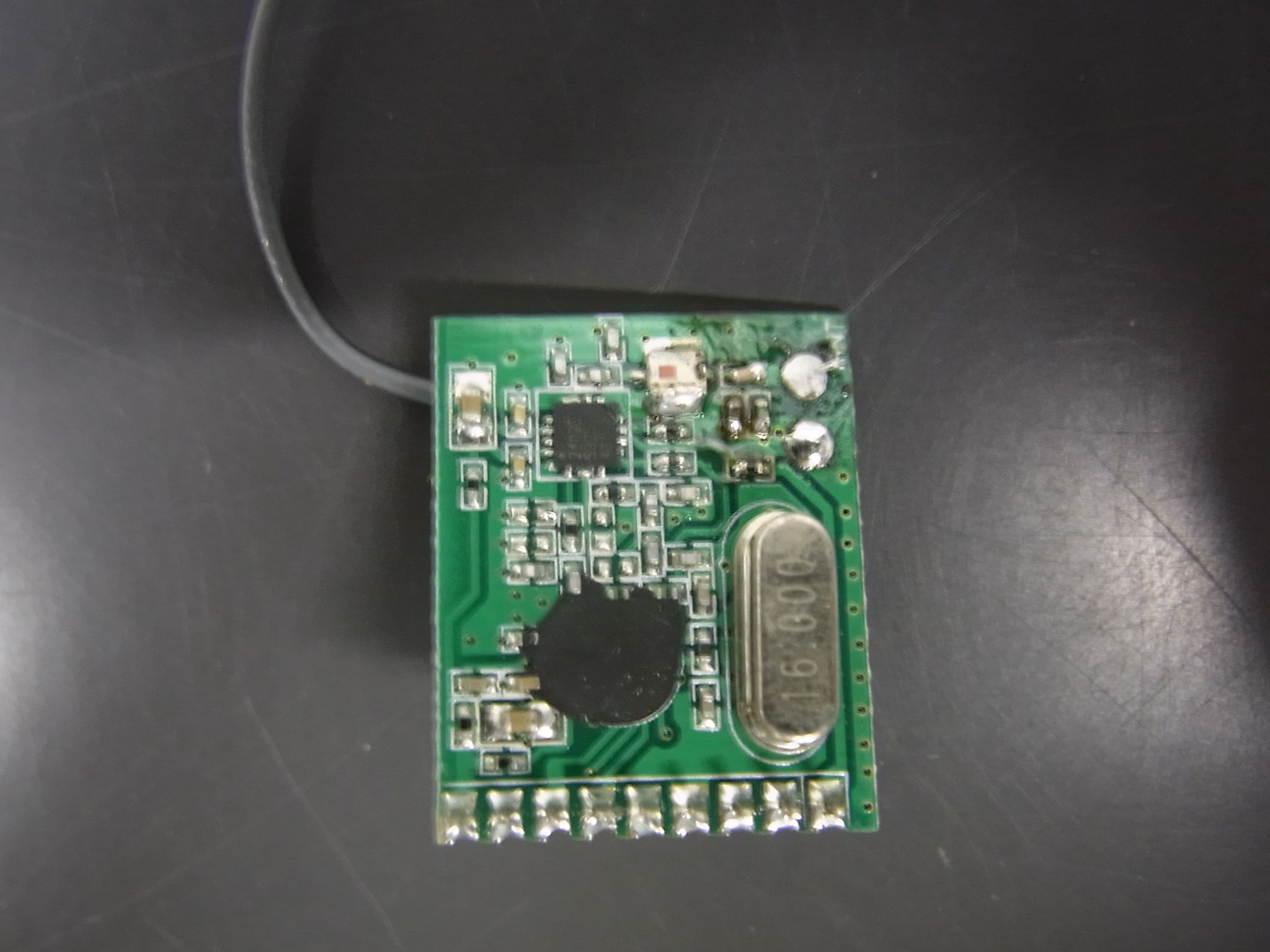
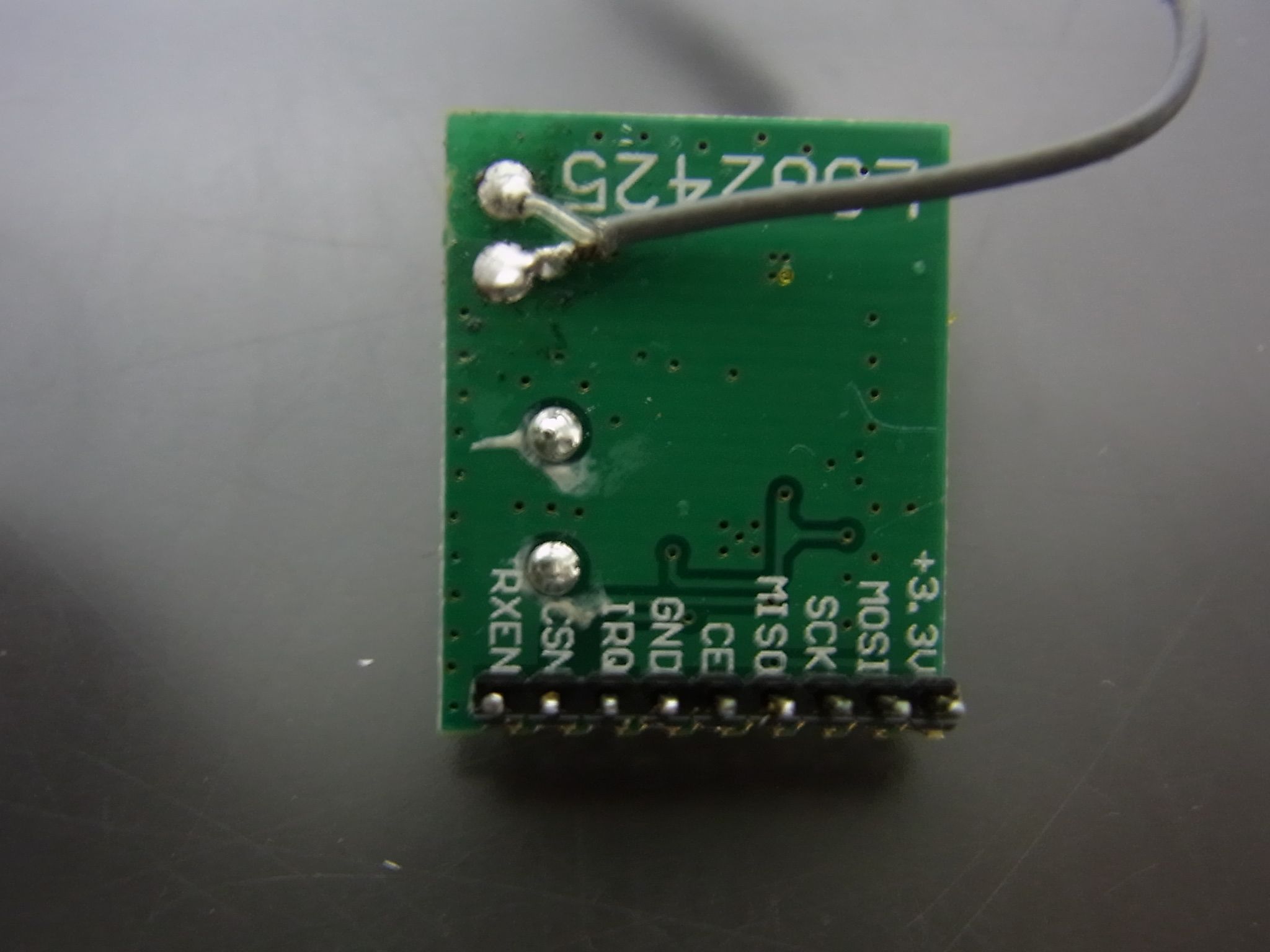
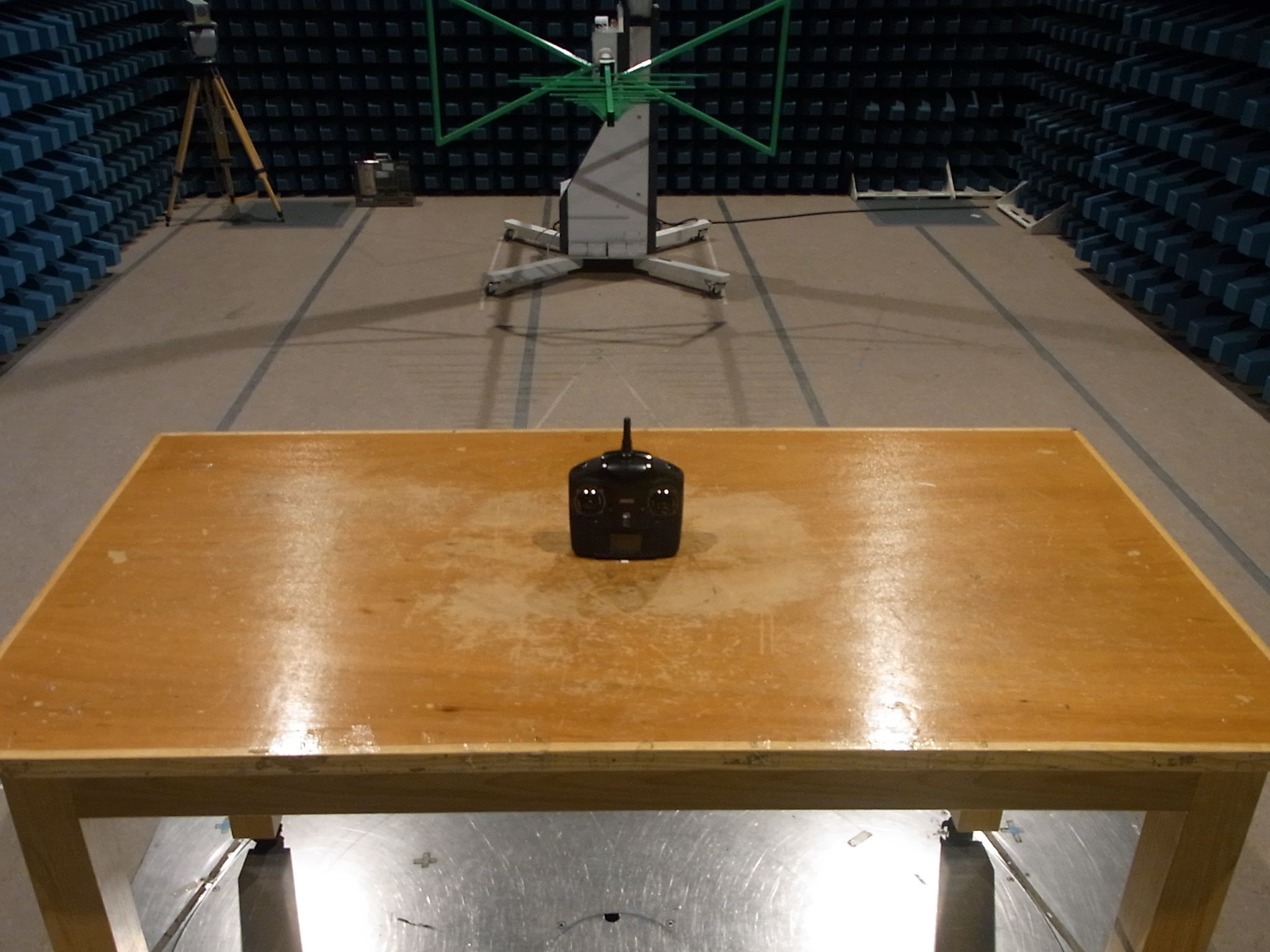
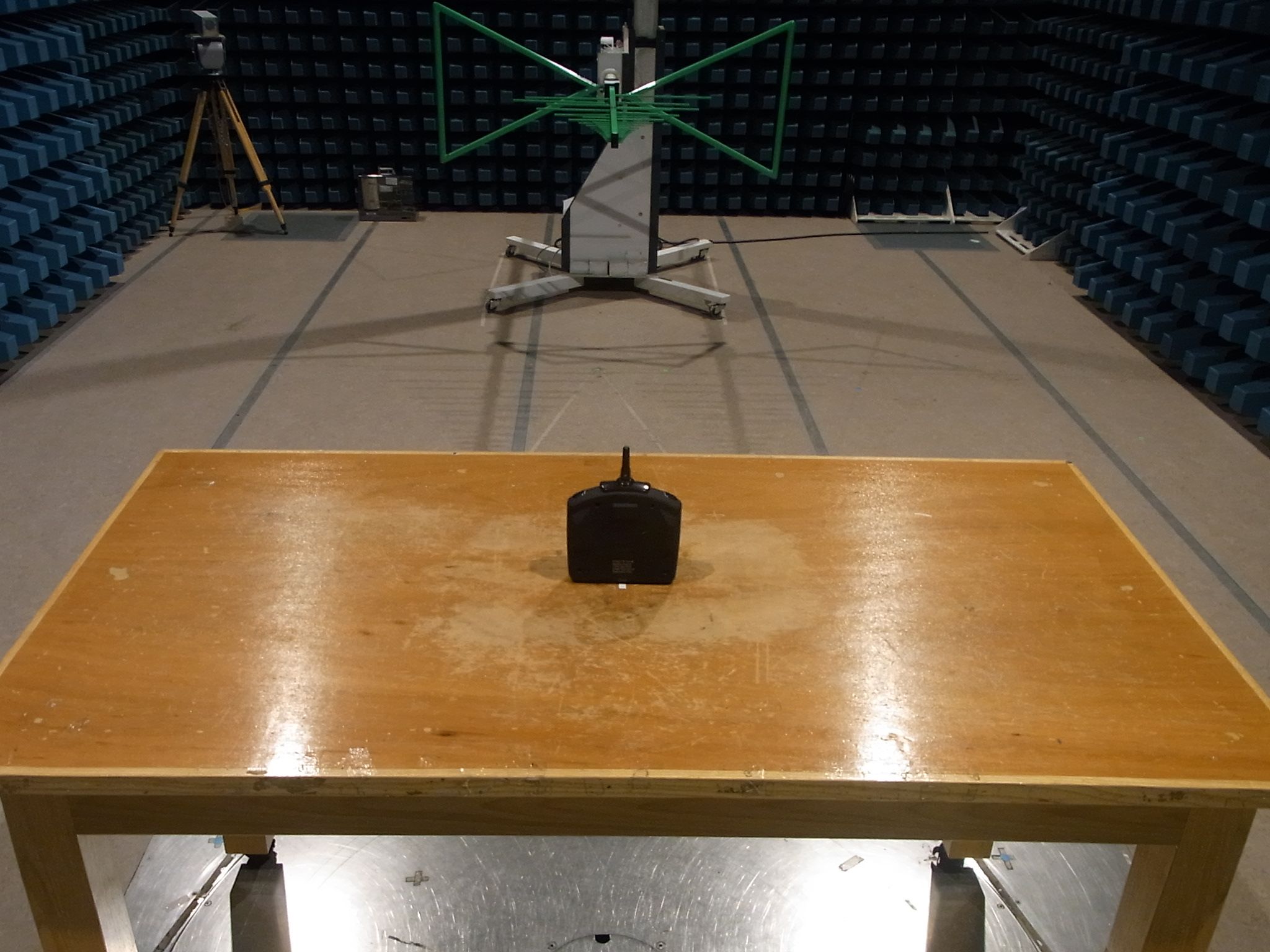
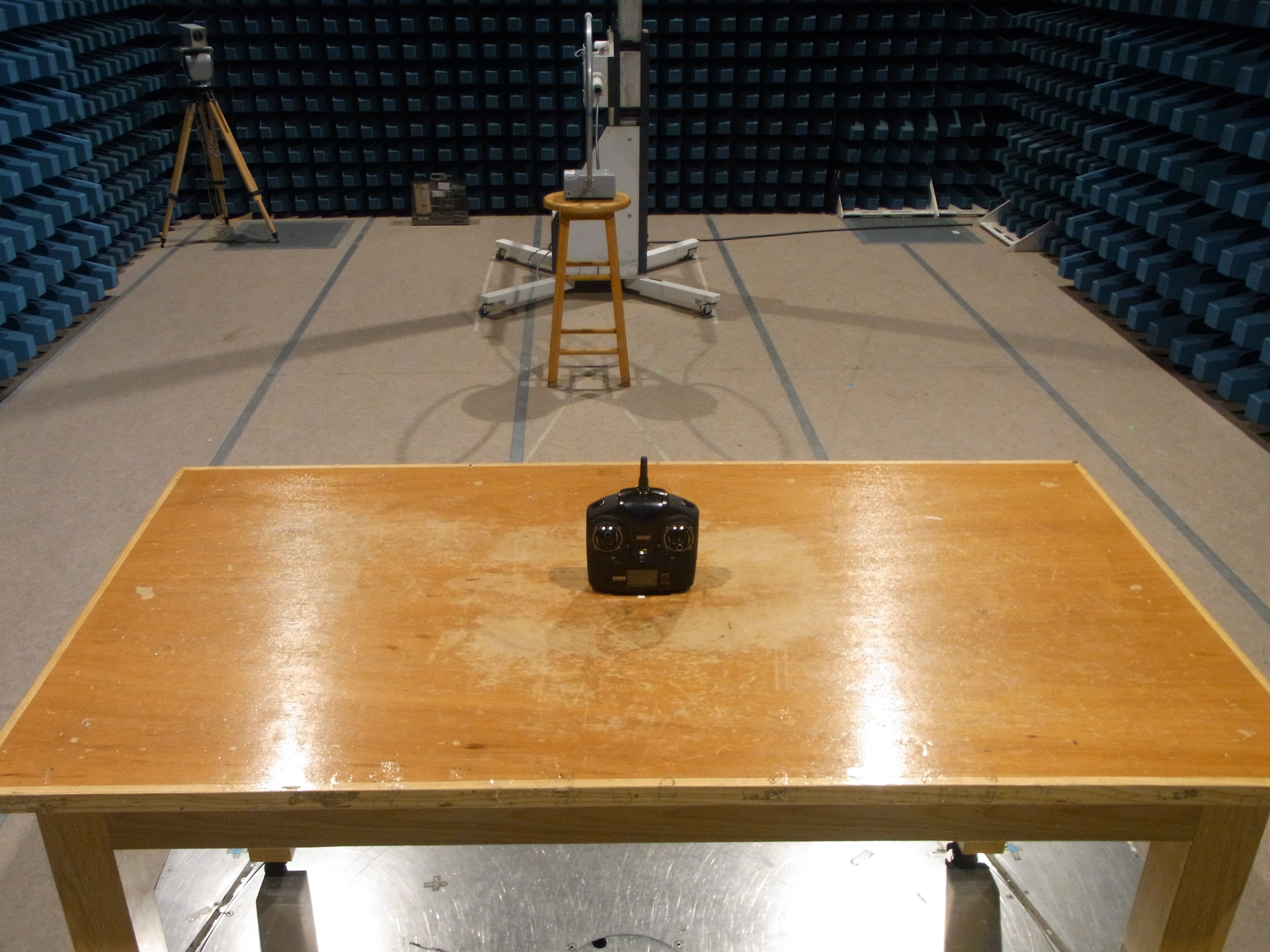
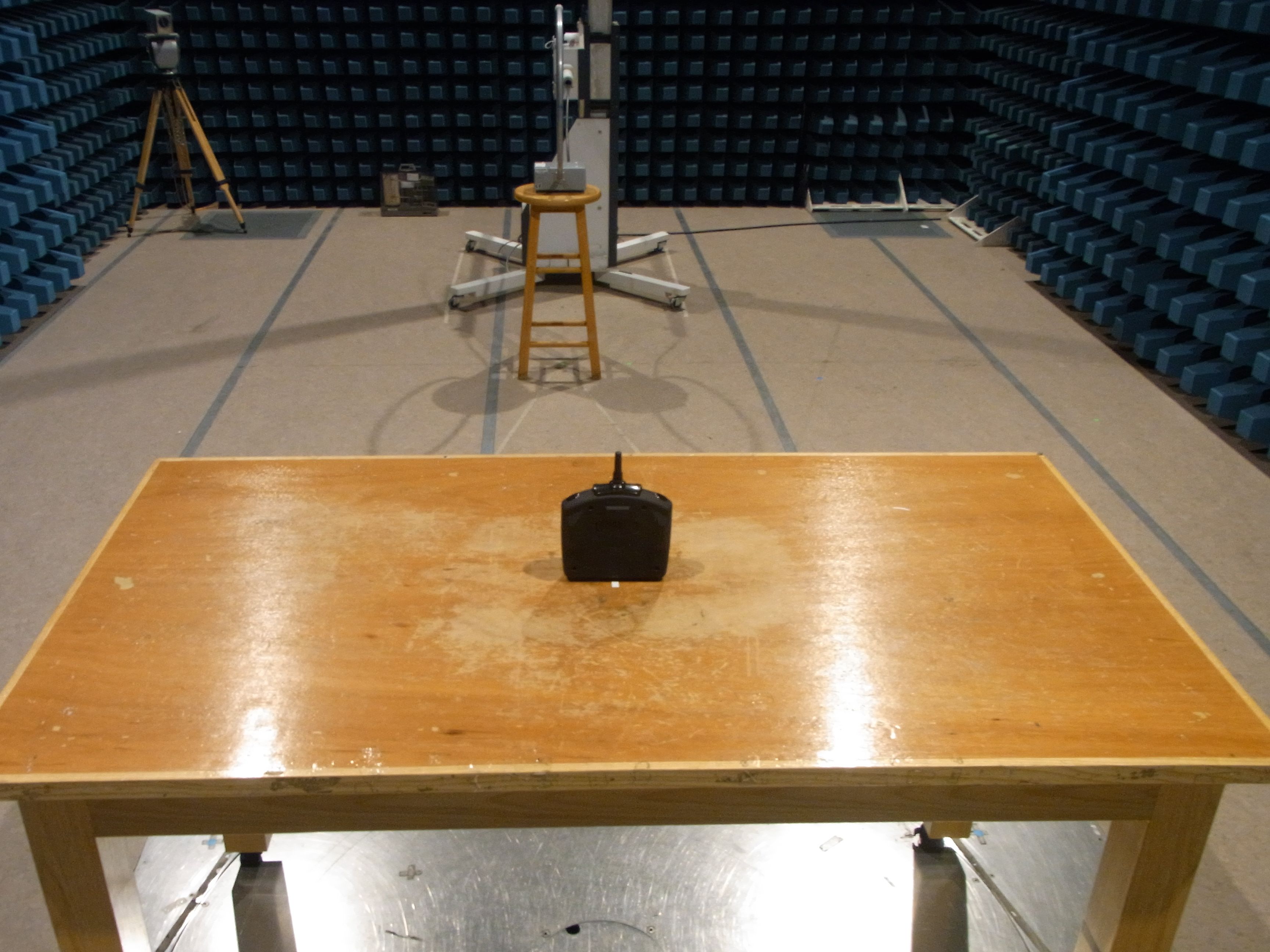
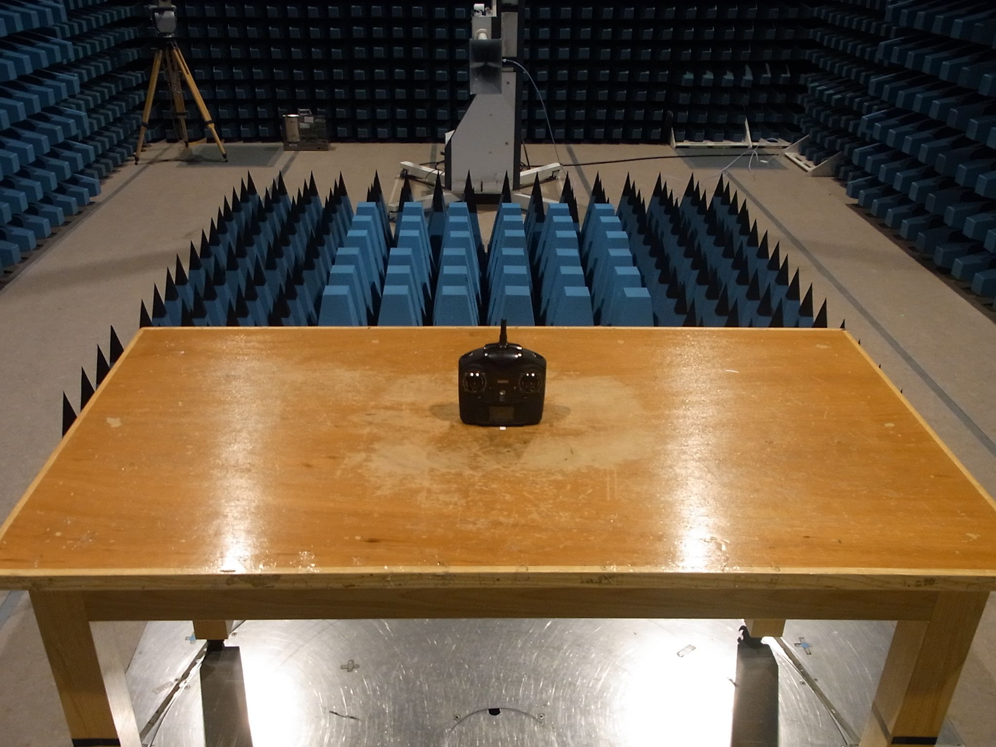
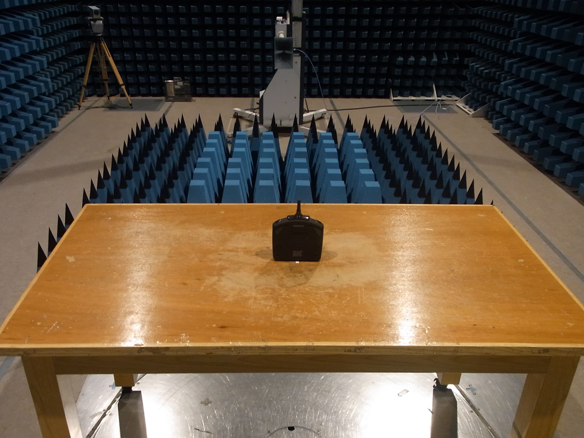
TEST REPORT Report No. : AR0058699(4) Date : 17 Oct 2013 For and on behalf of CMA Industrial Development Foundation Limited Authorized Signature : Page 1 of 36 Mr. WONG Lap-pong, Andrew Assistant Manager Electrical Division FCC ID: VLEPL1180-T Application No. : LR034601(3) Applicant : 4F,-4, No.669 Jingping Rd., Zhonghe City, TaiPei county 235 Taiwan R.O.C, Taiwan Client : Asian Express Holdings Limited Rm804 Sino Centre,582-592 Nathan Road, Mongkok, Kowloon, Hong Kong. Sample Description : One(1) item of submitted sample stated to be Zephyrus / Quad Copter of Model No. PL-1180 Sample registration No. : RR037918-001, RR040762-001 and RR041740-001 Radio Frequency : 2417MHz – 2458 MHz Transmitter Rating : 6 x 1.5V AA size batteries No. of submitted sample : One (3) piece (s) Date Received : 11 Sep 2013, 27 Sep 2013, 09 Oct 2013 Test Period : 23 Sep 2013 to 16 Oct 2013. Test Requested : FCC Part 15 Certificate Test Method : 47 CFR Part 15 (10-1-12 Edition) ANSI C63.4 – 2009 Test Engineer : Mr. LEUNG Shu-kan, Ken Test Result : See attached sheet(s) from page 2 to 36. Conclusion : The submitted sample was found to comply with requirement of FCC Part 15 Subpart C. TEST REPORT Report No. : AR0058699(4) Date : 17 Oct 2013 Page 2 of 36 FCC ID: VLEPL1180-T Table of Contents 1 General Information ................................................................................................................................... 3 1.1 General Description ............................................................................................................................ 3 1.2 Location of the test site ....................................................................................................................... 4 1.3 List of measuring equipment............................................................................................................... 5 1.4 Measurement Uncertainty ................................................................................................................... 6 2 Description of the radiated emission test ................................................................................................... 7 2.1 Test Procedure .................................................................................................................................... 7 2.2 Test Result .......................................................................................................................................... 8 2.3 Radiated Emission Measurement Data ............................................................................................... 9 3 Description of the Line-conducted Test ................................................................................................... 11 3.1 Test Procedure .................................................................................................................................. 11 3.2 Test Result ........................................................................................................................................ 11 3.3 Graph and Table of Conducted Emission Measurement Data .......................................................... 11 4 Photograph ...............................................................................................................................................12 4.1 Photographs of the Test Setup for Radiated Emission and Conducted Emission ............................. 12 4.2 Photographs of the External and Internal Configurations of the EUT.............................................. 12 5 Supplementary document ......................................................................................................................... 13 5.1 Bandwidth ......................................................................................................................................... 13 5.2 Duty cycle ......................................................................................................................................... 13 5.3 Transmission time ............................................................................................................................. 13 5.4 Power Spectral Density..................................................................................................................... 13 5.5 Average on time ................................................................................................................................ 13 6 Appendices...............................................................................................................................................14 TEST REPORT Report No. : AR0058699(4) Date : 17 Oct 2013 Page 3 of 36 FCC ID: VLEPL1180-T 1 General Information 1.1 General Description The equipment under test (EUT) is a transmitter for quadrocopter. The EUT is power by 6 x 1.5V AA size batteries. It operates at 2417MHz – 2458 MHz. There are buttons and joysticks on the EUT. When the buttons are pressed or the joysticks are moved, the EUT will transmit radio control signal to receiver. The brief circuit description is listed as follows: - IC1 and its associated circuit act as MCU - IC2, IC3, IC4 and its associated circuit act as power - IC1 (module), IC2 (module) and its associated circuit act as RF module - S2, S3, S4, S5, S6, S7, S8, S9, S10, S11, RW1, RW2 and its associated circuit act as copter control TEST REPORT Report No. : AR0058699(4) Date : 17 Oct 2013 Page 4 of 36 FCC ID: VLEPL1180-T 1.2 Location of the test site FCC Registered Test Site Number: 552221 Radiated emissions measurements are investigated and taken pursuant to the procedures of ANSI C63.4 – 2009. A Semi-Anechoic Chamber Testing Site is set up for investigation and located at: Ground Floor, Yan Hing Centre, 9 – 13 Wong Chuk Yeung Street, Fo Tan, Shatin, New Territories, Hong Kong. Conducted emissions measurements are investigated and also taken pursuant to the procedures of ANSI C63.4 – 2009.…
Text truncated - open the document above for the full version.
Test Report
TEST REPORT Report No. : AR0058699(4) Date : 17 Oct 2013 Tested by: Reviewed by: Mr. LEUNG Shu-kan, Ken Mr. WONG Lap-pong, Andrew Page 26 of 36 FCC ID: VLEPL1180-T A5. Band Edge Edge 1 Edge 2
Contact Information
Applicant
Nancy Chen(QA Manager)
Test Firm
CMA Industrial Development Foundations LimitedAndrew Wong
Technical Specifications
| # | Rule Parts | Frequency Range | Power Output |
|---|---|---|---|
| 1 | 15C | 2.42 GHz - 2.46 GHz | - |
Other Applications from Asian Express Holdings Limited
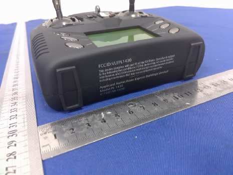
VLEPL1431
Dec 06, 2015Cloud Rider Drone
Equipment Class
DXX - Part 15 Low Power Communication Device Transmitter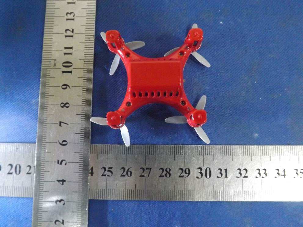
VLE1392-R
Nov 16, 2015Air Micro Drone
Equipment Class
DXX - Part 15 Low Power Communication Device Transmitter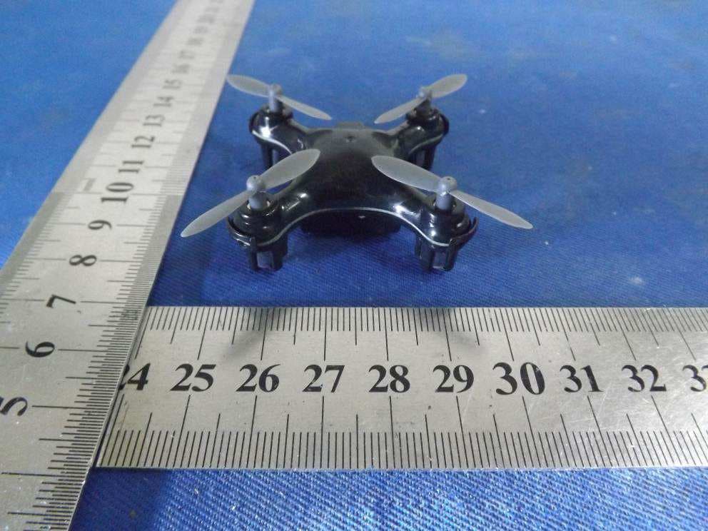
VLE1470R
Nov 16, 2015ZIP Micro Drone
Equipment Class
DXX - Part 15 Low Power Communication Device Transmitter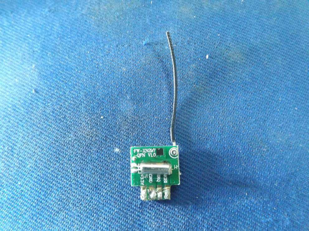
VLE1392
Nov 16, 2015Air Micro Drone
Equipment Class
DXX - Part 15 Low Power Communication Device Transmitter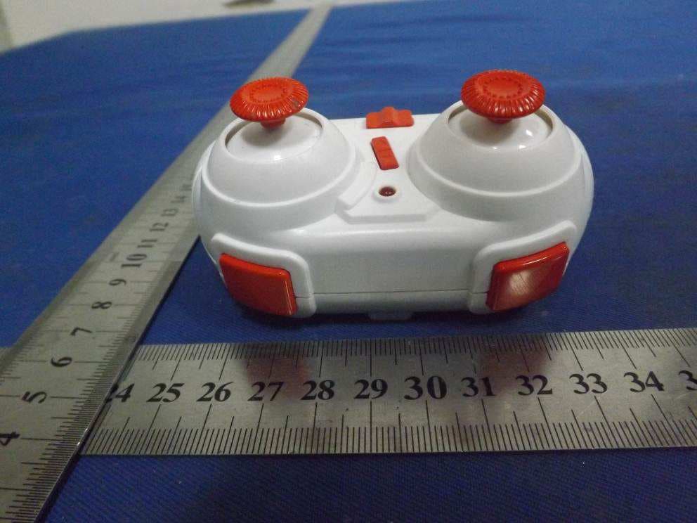
VLE1470
Nov 16, 2015Zip Micro Drone
Equipment Class
DXX - Part 15 Low Power Communication Device Transmitter