VNE000TTK550TOWING MONITOR
Tattle-Trail LLC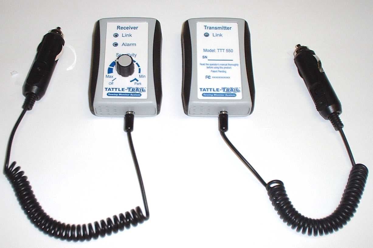
Click to zoom
Application Details
- Equipment Class
- DXT - Part 15 Low Power Transceiver, Rx Verified
- Date of Grant
- Oct 07, 2007
- Application Purpose
- Original Equipment
- Date of Application
- Sep 30, 2007
- Equipment Note
- TOWING MONITOR
- Frequency Range
- 2410.00000000 - 2475.00000000
- Company
- Tattle-Trail LLC
- Country
- United States
Documents & Files
Document Text
Text extracted from the exhibit documents filed with the FCC. Open a document above to read the original.
Users Manual
Operators Manual Model TTK 550 Portable Car Monitoring System Document No. MA-002 © 2007 Rev 3 -2- Table of Contents FCC Information ...................................................... 3 Introduction .............................................................. 5 Installation:............................................................... 6 Transmitter ............................................................... 6 Receiver ................................................................... 7 Operation Inst ructions.............................................. 8 “Park” M onitor....................................................... 10 Trouble Shooti ng Guid e......................................... 13 Warranty: ............................................................... 15 FCC Information This device complies with part 15 of the FCC rules. Operation is subject to the following two conditions: (1) this device may not cause harmful interference, and (2 ) this device must accept any interference received, including interference that may cause undesired operation. Caution: Any changes or modifica tions not expressly approved by Tattle-Trail LLC could void the us er's authority to operate the equipment. This equipment has been tested a nd found to comply with the limits for a Class B digital device, pursuan t to part 15 of the FCC Rules. These limits are designed to provi de reasonable protection against harmful interference in a resident ial installation. This equipment generates, uses and can radiate radio frequency energy and, if not installed and used in accordance with the instructions, may cause harmful interference to radio comm unications. However, there is no guarantee that interference will not occur in a particular installation. If this equipment does cause harmful interference to radio or television reception, which can be determined by turning the equipment off and on, the user is en couraged to try to correct the interference by one or more of the following measures: 1. Reorient or relocate the rece iving antenna. 2. Increase the separation be tween the equipment and receiver. 3. Connect the equipment i nto an outlet on a circuit different from that to which the receiver is connected. 4. Consult the dealer or an experienced radio/TV technician for help. Medical: Consult the manufacture of any personal medical devices, such as pacemakers or hearing aids, to determine if they are ad equately shielded from external RF (radio freque ncy) energy, (The product -4- operates in the frequency range of 2.405 GHz to 2.480 GHz, and the power output is 200mW (max.).) -5- Tattle-Trail Monitoring System* Introduction The Tattle-Trail monitoring syst em is designed to sense the amount of vibration on vehicles towed behind a truck, RV or toterhome. When m onitored parameters on the towed unit exceed what the ope rator sets as normal, both audible and visual alarms ar e generated. Once notified, the operator can take action to prevent further property damage. Depending on the sensitivity setti ng selected and the type of towed unit, Tattle-Trail may be able to detect abnormal vibration levels. Some failures that may cause increased vibration are: tire tread separation, flat tire, loose lug nuts, broken suspension components, malfunction of hitch assembly and runaway of the towed unit. Additionally, if the “Sensitivity” knob is placed in the “Park” mode and the Tattle-Trail units are w ithin communication range, theft detection may be sensed. The portable TTK 550 Tattle-Tra il system is not designed to be exposed to the elements. Always ensure that this unit is installed inside both vehicles and not exposed to the weather. If a water resistant transmitter enclosure is required, Tattle-Trail LLC offers a weather hardened enclosure (Model TTK 700) designed for permanent mounting to a towed unit. Check www.Tattle-Trail.com for more details. -6- * Tattle-Trail is a trademark of Tattle-Trail LLC Installation: Transmitter Tattle-Trail Model TTK 550 is a “plug and play” system that is highly portable and requires no user calibration. To use, simply follow these instructions: Remove the unit marked “Transmitter” from the carrying case and locate a mounting area high and in the center of the towed unit’s windshield (up near the mirror but not obstructing driver’s vision ). With the power cord facing down and forward, moisten the suction cups and firmly press the unit to the windshield (see Figure 1). Then plug the male 12VDC power plug into the closest powered 12VDC receptacle. A flashi ng green “Link” light will illuminate indicating that the “Transmitter” has power and is self calibrating. The “Link” light will quickly turn solid green indicating that the unit has calibrated and is transmitting data. -7- Towed Vehicle Figure 1 Note: During the flashing green calibration mode, minimize any motion in the towed unit. Warning: Both Tattle-Trail units are internally fused, but it is important to protect the wiring going to the unit by utilizing a fused power source. Warning: Do not ever submerge either the transmitter or receiver in fluid. Once the transmitter has calibrate d, it tries to “Link” with the receiver. After 3 minutes, if the receiver is not turned “On”, the transmitter will go into “Sleep” mode to conserve power. Every 5 s econds, the transmitter wakes up to look for a signal from the receiver. If no “Link” is established, then the transm itter returns to “Sleep” mode. Receiver Remove the unit marked “Receiver” from the carrying case. Rotate the “Sensitivity” knob to the full counterclockwise (CCW) “OFF” position. Now, with the towing vehicle parked, plug in the male 12VDC power connector into a powered receptacle of the towing vehicle. With the towed un it’s “Transmitter” powered up and calibrated, turn on the “Receiver” and set the sensitivity knob at about 2 o-clock. Both the green “Link” light and the green “Alarm” light should be illuminated. Since dash configurations vary from v…
Text truncated - open the document above for the full version.
Cover Letter(s)
October 3, 2007 Federal Communications Commission Authorization and Evaluation Division Confidentiality Request regarding application for certification of FCC ID: VNE000TTK550 Pursuant to Sections 0.457 and 0.459 of the Commission’s Rules, we hereby request confidential treatment of information accompanying this application as outlined below: Exhibit Type File Name Block Diagram Block Dia.pdf Operational Description / Circuit Description TheoryOfOPerationV2.10.pdf Schematics Schematic.pdf The above materials contain trade secrets and proprietary information not customarily released to the public. The public disclosure of these materials may be harmful to the applicant and provide unjustified benefits to its competitors. The applicant understands that pursuant to Section 0.457 of the Rules, disclosure of this application and all accompanying documentation will not be made before the date of the Grant for this application. Pursuant to DA04-1705 June 15, 2004 of the Commission’s public notice, we also request temporary confidential treatment of information accompanying this application as outlined below: Exhibit Type File Name User Manual UserManualTTK 550FCC.R3.pdf Sincerely, Shahid Din Vice President Tattle-Trail LLC 7887 BRYAN DAIRY RD• SUITE 220 • LARG0 FL • 33777 PHONE 727-230-9438•FAX 727-230-6836
Cover Letter(s)
September 25, 2007 Federal Communications Commission Authorization and Evaluation Division 1919 M Street N.W. Washington DC 20554 Dear Sir or Madam: Model Variance Explanation for certification of FCC ID: VNE000TTK550 The above FCC ID is marketed with two different names, transmitter and receiver.. Both have the same PCB board. The receiver just misses some components. If you have questions in regards to this device please contact us. Sincerely, Shahid Din Vice President Tattle-Trail LLC 7887 BRYAN DAIRY RD• SUITE 220 • LARG0 FL • 33777 PHONE: 727-230-9438 • FAX: 727-230-6836
External Photos
Rear View of Samples Size 2/5 ” X 3.5 ”
ID Label/Location Info
FCC ID Label & Location FCC ID: VNE000TTK500 For units used as receiver only- receiver front For units used as transmitter only – transmitter front
Internal Photos
TTK 550 Transceiver with open enclosure /PCB Transmitter PCB Component Layer 16 Mhz Crystal F-Antenna Power Supply Processor / RF Modem EMI Filters Receive LNA RF T/R Switch Figure xx Balun Accelerometer Transmitter PCB Bottom Layer F-Antenna Power Input Figure xx Printed Circuit Boards Receiver PCB Top Layer 16 Mhz Crystal F-Antenna Power Supply Processor / RF Modem EMI Filters Balun Receive LNA RF T/R Switch Figure xx Receiver PCB Bottom Layer F-Antenna Buzzer Power Input Figure xx
Test Report
849 NW State Road 45 Newberry, FL 32669 USA Ph: 888.472.2424 or 352.472.5500 Fax: 352.472.2030 Email: [email protected] Website: www.timcoengr.com COMPLIANCE TEST REPORT PER FCC PT 15.249 UNLICENSED INTENTIONAL RADIATOR Applicant Tattle-Trail LLC Address 7887 Bryan Dairy Road Largo FL 33377 FCC ID VNE000TTK550 Model Number TTT 550, TTR 550 Product Description Towing Monitor Date Sample Received 9/14/2007 Date Tested 9/14/2007 Tested By Mario de Aranzeta Approved By Mario de Aranzeta Report Number 3044BUT7TestReport.pdf Test Results PASS FAIL THE ATTACHED REPORT SHALL NOT BE REPRODUCED EXCEPT IN FULL WITHOUT THE WRITTEN APPROVAL OF TIMCO ENGINEERING, INC. Certificate # 0955-01 APPLICANT: Tattle-Trail LLC FCC ID: VNE000TTK550 REPORT #: T\Tattle\3044BUT7\3044BUT7TestReport Page 2 of 15 TABLE OF CONTENT ATTESTATION ...................................................................................................................................3 REPORT SUMMARY ..........................................................................................................................4 TEST ENVIRONMENT AND TEST SETUP ...........................................................................................4 DUT SPECIFICATION ........................................................................................................................5 EMC EQUIPMENT LIST .....................................................................................................................6 TEST PROCEDURES .........................................................................................................................7 RADIATION INTERFERENCE.............................................................................................................8 OCCUPIED BANDWIDTH...................................................................................................................9 BAND EDGE COMPLIANCE.............................................................................................................10 DUTY CYCLE...................................................................................................................................14 POWER LINE CONDUCTED INTERFERENCE ..................................................................................15 APPLICANT: Tattle-Trail LLC FCC ID: VNE000TTK550 REPORT #: T\Tattle\3044BUT7\3044BUT7TestReport Page 3 of 15 ATTESTATION The attached report shall not be reproduced except in full without the written permission of Timco Engineering Inc. Summary The device under test does: fulfill the general approval requirements as identified in this test report not fulfill the general approval requirements as identified in this test report Attestations This equipment has been tested in accordance with the standards identified in this test report. To the best of my knowledge and belief, these tests were performed using the measurement procedures described in this report. All instrumentation and accessories used to test products for compliance to the indicated standards are calibrated regularly in accordance with ISO 17025 requirements. Certificate # 0955-01 I attest that the necessary measurements were made, under my supervision, at: Timco Engineering Inc. 849 NW State Road 45 Newberry, Fl 32669 Authorized Signatory Name: Mario de Aranzeta Mario de Aranzeta C.E.T. Compliance Engineer/ Lab. Supervisor Date: September 19, 2007 Signature: On file APPLICANT: Tattle-Trail LLC FCC ID: VNE000TTK550 REPORT #: T\Tattle\3044BUT7\3044BUT7TestReport Page 4 of 15 REPORT SUMMARY Disclaimer The test results relate only to the items tested. Purpose of Test To show the DUT in compliance with FCC CFR 47, Part 15.249 requirements for a low power transmitter Test Standards ANSI/TIA 603-C: 2004, FCC CFR 47 Part 15.249, ANSI C63.4: 2003 Related Report(s)/Approval(s) 3044AUT7TestReport.pdf – Digital interface portion was verified. TEST ENVIRONMENT AND TEST SETUP Test Facility All tests were conducted by Timco Engineering Inc. located at 849 NW State Road 45, Newberry, FL 32669 USA Laboratory Test Condition Temperature: 26ºC Relative humidity: 50% Deviation from the standards No deviation Modification to the DUT No modification was made. Test Exercise (software etc.) The DUT was placed in continuous transmitting mode of operation. System Setup Stand alone device. APPLICANT: Tattle-Trail LLC FCC ID: VNE000TTK550 REPORT #: T\Tattle\3044BUT7\3044BUT7TestReport Page 5 of 15 DUT SPECIFICATION DUT Description Towing monitor FCC ID VNE000TTK550 Model Number TTT 550, TTR 550 Serial Number N/A Operating Frequency 2410 – 2475 MHz No. of Channels 14 Modulations ZigBee DUT Power Source Battery Operated Exclusively Test Item Pre-production Type of Equipment Portable Antenna Printed Circuit Board F Antenna Connector None APPLICANT: Tattle-Trail LLC FCC ID: VNE000TTK550 REPORT #: T\Tattle\3044BUT7\3044BUT7TestReport Page 6 of 15 EMC EQUIPMENT LIST Device Manufacturer Model Serial Number Cal/Char Date Due Date 3/10-Meter OATS TEI N/A N/A Listed 3/20/07 3/19/10 3-Meter OATS TEI N/A N/A Listed 1/11/06 1/10/09 Antenna: Biconnical Eaton 94455-1 1057 CAL 12/12/05 12/12/07 Antenna: Biconnical Eaton 94455-1 1096 CAL 10/11/06 10/11/08 Antenna: Biconnical Electro- Metrics BIA-25 1171 CAL 7/18/07 7/18/09 Analyzer Blue Tower Quasi-Peak Adapter HP 85650A 2811A01279 CAL 5/17/07 5/17/09 Analyzer Blue Tower RF Preselector HP 85685A 2926A00983 CAL 5/17/07 5/17/09 Analyzer Blue Tower Spectrum Analyzer HP 8568B 2928A04729 2848A18049 CAL 5/17/07 5/17/09 LISN Electro- Metrics ANS-25/2 2604 CAL 10/5/06 10/5/08 LISN Electro- Metrics EM-7820 2682 CAL 7/23/07 7/23/09 Antenna: Log-Periodic Eaton 96005 1243 CAL 12/14/05 12/14/07 APPLICANT: Tattle-Trail LLC FCC ID: VNE000TTK550 REPORT: T\Tattle\3044BUT7\3044BUT7TestReport Page 7 of 15 TEST PROCEDURES Radiation Interference: ANSI C63.4-2003 using an Agilent Model 8566B spectrum analyzer, an Agilent Model 85685A preselector, an Agilent Model 85650A Quasi-Peak adapt…
Text truncated - open the document above for the full version.
Contact Information
Applicant
Shahid Din(Vice President)
Test Firm
Timco Engineering, Inc.Sid Sanders
Technical Specifications
| # | Rule Parts | Frequency Range | Power Output |
|---|---|---|---|
| 1 | 15C | 2.41 GHz - 2.48 GHz | - |