VNR-E32ED-X5B-002.4GHz IEEE802.15.4 compliant antenna diversity radio transceiver
Atmel Germany GmbH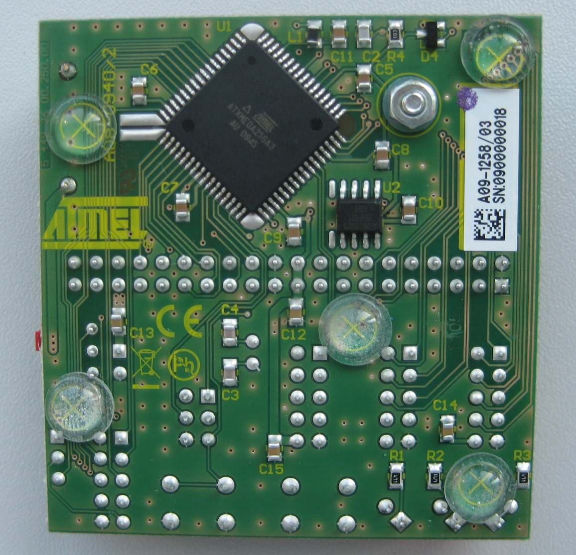
Click to zoom
Application Details
- Equipment Class
- DTS - Digital Transmission System
- Date of Grant
- Feb 09, 2012
- Application Purpose
- Original Equipment
- Date of Application
- Sep 26, 2011
- Equipment Note
- 2.4GHz IEEE802.15.4 compliant antenna diversity radio transceiver
- Frequency Range
- 2405.00000000 - 2480.00000000
- Company
- Atmel Germany GmbH
- Country
- Germany
Documents & Files
Document Text
Text extracted from the exhibit documents filed with the FCC. Open a document above to read the original.
Users Manual
Atmel AVR2042: REB Controller Base Board - Hardware User Manual Features • High-performance, low-power Atmel ® 8/16-bit AVR ® XMEGA ® microcontroller ATxmega256A3 - 256KB in-system, self-programmable flash - 8KB boot code section with independent lock bits - 16KB internal SRAM - 4KB EEPROM • 2Mb serial flash for support of over-the-air (OTA) upgrades • Programming interface • Fully functional wireless node in combination with the Atmel Radio Extender Board (REB) • Powered by two AAA batteries for stand-alone operation 1 Introduction This application note describes the Atmel REB Controller Base Board (REB-CBB). Detailed information about its functionality, its interfaces, the microcontroller programming, and the PCB design is given in the individual sections. The REB-CBB is intended to serve as a microcontroller platform for the Atmel Radio Extender Board (REB) family. The REB connected to a REB-CBB forms a battery powered, fully functional, and portable wireless node. Figure 1-1. REB controller base board. 8-bit Atmel Microcontrollers Application Note Rev. 8334A-AVR-05/11 2 Atmel AVR2042 8334A-AVR-05/11 2 Disclaimer Typical values contained in this application note are based on simulations and on testing of individual examples. Any information about third-party materials or parts is included in this document for convenience. The vendor may have changed the information that has been published. Check the individual vendor information for the latest changes. Atmel AVR2042 3 8334A-AVR-05/11 3 Overview The Atmel REB-CBB is designed to interface directly to a radio extender board. The combination of the two boards form a battery powered, fully functional, portable wireless node. The setup provides an ideal platform to: Evaluate the outstanding performance of the Atmel radio transceivers Test the unique radio transceiver hardware support for the IEEE ® 802.15.4 standard [3] Test the enhanced radio transceiver feature set Develop applications capable of hosting a ZigBee ® stack The following table lists the available radio extender boards and related radio transceivers. Table 3-1. Supported radio extender boards. Board name Comment Radio transceiver REB230 SMA connector AT86RF230 REB231 SMA connector AT86RF231 REB231ED Antenna diversity AT86RF231 REB212 SMA connector AT86RF212 The REB-CBB is assembled with an Atmel 8-bit AVR ATxmega256A3 microcontroller. It offers a connector for programming and debugging, suitable to connect an Atmel JTAGICE mkII programmer. A connector to attach an asynchronous serial interface allows interfacing to a PC host for control and data exchange tasks. Figure 3-1 shows a development and evaluation setup using the REB-CBB in combination with the REB231ED radio extender board. 4 Atmel AVR2042 8334A-AVR-05/11 Figure 3-1. Atmel REB-CBB connected to an Atmel REB231ED with an RS232 cable plugged in and an Atmel JTAGICE mkII programming interface. Atmel AVR2042 5 8334A-AVR-05/11 4 Mechanical description The REB-CBB is manufactured using a two-layer printed circuit board (PCB). All active components are mounted on the bottom side, and all connectors and user I/Os are located on the top side using through-hole components. The radio extender board is plugged into the 2 x 20 female header, Expand1, vertically. Figure 4-1. Mechanical outline. Table 4-1. REB-CBB mechanical dimensions. Dimension Value Width x 57mm Width y 60mm PCB standoff height 5mm Height without REB 18mm Height with REB231ED plugged in 70mm 5 mm 5mm 18mm 60mm 57mm 70mm 6 Atmel AVR2042 8334A-AVR-05/11 5 Functional description The Atmel REB-CBB carries a high-performance Atmel AVR XMEGA microcontroller, which connects to the radio extender board and various peripheral units (see Figure 5-1). It is powered by two AAA batteries or optionally by applying an external voltage source. Figure 5-1. REB-CBB block diagram. 5.1 Power supply The board is powered by two AAA batteries. The power switch, SW1, disconnects batteries from the entire board. External power is not routed through the power switch. For debugging and test purposes, power can also be supplied at pin header PWR. NOTE There is no protection against over voltage. Take care when applying power from an external source. Refer to Section 7.1 for allowable input voltage range. Exceeding these limits may destroy the board. In addition, avoid applying reverse currents into batteries by switching SW1 to the off position, or by removing the batteries when using external power Figure 5-2. Power supply of the REB-CBB. 5.2 Microcontroller The Atmel XMEGA A3 is a family of low-power, high–performance, and peripheral- rich CMOS 8/16-bit microcontrollers based on the AVR enhanced RISC architecture. By executing powerful instructions in a single clock cycle, the Atmel XMEGA A3 achieves throughputs of up to 1 million instructions per second (MIPS) per MHz, allowing the system designer to optimize power consumption versus processing Atmel AVR2042 7 8334A-AVR-05/11 speed. A detailed description of the Atmel ATxmega256A3 can be found in the datasheet [2]. Table 5-1. ATxmega256A3 ordering information. Ordering code Flash EEPROM SRAM Speed (MHz) Power supply Package Temperature ATxmega256A3-AU 256KB + 8KB 4KB 16KB 32 1.6V – 3.6V 64A TQFP-64 -40°C – 85°C 5.3 Clock sources The XMEGA has a flexible clock system, supporting a large number of clock sources. It incorporates both calibrated integrated oscillators and external crystal oscillators, and resonators. The Atmel AVR XMEGA family allows dynamic switching between the clock sources. Internal clock sources are: 32kHz RC oscillator 2MHz RC oscillator 32MHz RC oscillator The 2/32MHz oscillators can be calibrated using an automatic runtime calibration feature. In addition to the internal clock sources, two different external clock sources are supported: The 32.768kHz crystal oscillator connected to TOSC1/2 delivers an accurate clock for a real-time counter, or optionally a system clock for XMEGA The transceiver clo…
Text truncated - open the document above for the full version.
Users Manual
Atmel AVR2092: REB232ED - Hardware User Manual Features • High-performance, 2.4GHz, RF-CMOS Atmel ® AT86RF232 radio transceiver targeted for IEEE ® 802.15.4, ZigBee ® , and ISM applications - Industry leading 104dB link budget - Ultra-low current consumption - Ultra-low supply voltage (1.8V to 3.6V) • Hardware supported antenna diversity • RF reference design and high-performance evaluation platform • Interfaces to several of the Atmel microcontroller development platforms • Board information EEPROM - MAC address - Board identification, features, and serial number - Crystal calibration values 1 Introduction This manual describes the REB232ED radio extender board supporting antenna diversity in combination with the Atmel AT86RF232 radio transceiver. Detailed information is given in the individual sections about the board functionality, the board interfaces, and the board design. The REB232ED connects directly to the REB controller base board (REB-CBB), or can be used as an RF interface in combination with one of the Atmel microcontroller development platforms. The REB232ED together with a microcontroller forms a fully functional wireless node. Figure 1-1. Top (with removed RF shield) and bottom views of the REB232ED. 8-bit Atmel Microcontrollers Application Note Rev. 8427A-AVR-10/11 2 Atmel AVR2092 8427A-AVR-10/11 2 Disclaimer Typical values contained in this application note are based on simulations and testing of individual examples. Any information about third-party materials or parts was included in this document for convenience. The vendor may have changed the information that has been published. Check the individual vendor information for the latest changes. Atmel AVR2092 3 8427A-AVR-10/11 3 Overview The radio extender board is assembled with an Atmel AT86RF232 radio transceiver [1] and two ceramic antennas, and demonstrates the unrivaled hardware-based antenna diversity feature, which significantly improves radio link robustness in harsh environments. The radio extender board was designed to interface to the Atmel microcontroller development or evolution platforms. The microcontroller platform in combination with the REB provides an ideal way to: • Evaluate the outstanding radio transceiver performance, such as the excellent receiver sensitivity achieved at ultra-low current consumption • Test the radio transceiver’s comprehensive hardware support of the IEEE 802.15.4™ standard • Test the radio transceiver’s enhanced feature set, which includes antenna diversity, AES, high data rate modes and other functions The photograph in Figure 3-1 sho ws a development and evaluation setup using the REB controller base board (REB-CBB) [2] in combination with th e REB232ED radio extender board. Figure 3-1. The REB232ED (with removed RF shield) connected to a REB-CBB. 4 Atmel AVR2092 8427A-AVR-10/11 4 Functional description The block diagram of the REB232ED radio extender board is shown in Figure 4-1. The power supply pins and all digital I/Os of the radio transceiver are routed to the 2 x 20-pin expansion connector to interface to a power supply and a microcontroller. The Atmel AT86RF232 antenna diversity (AD) feature supports the control of two antennas (ANT0/ANT1). A digital control pin (DIG1) is used to control an external RF switch selecting one of the two antennas. During the RX listening period, the radio transceiver switches between the two antennas autonomously, without the need for microcontroller interaction, if the AD algorithm is enabled. Once an IEEE 802.15.4 synchronization header is detected, an antenna providing sufficient signal quality is selected to receive the remaining frame. This ensures reliability and robustness, especially in harsh environments with strong multipath fading effects. Board-specific information such as board identifier, the node MAC address, and production calibration values are stored in an ID EEPROM. The SPI bus of the EEPROM is shared with the radio transceiver’s interface. Figure 4-1. REB232ED block diagram. RFP RFN DIG2 EXPAND1 Balun RF- Switch ANT0 ANT1 XTAL2 XTAL1 XTAL DIG1 CLKM Protection VDD VSS ID EEPROM SPI 4 IRQ RSTN SLPTR DIG4 DIG3 DIG2 TP6TP7 50Ohm JP1 4.1 Interface connector specification The REB is equipped with a 2 x 20-pin, 100mil expansion connector. The pin assignment enables a direct interface to the REB-CBB [2]. Further, the i nterface connects to the Atmel STK ® 500/501 microcontroller development platform to enable support for various Atmel 8-bit AVR ® microcontrollers. The REB is preconfigured to interface to an STK501 with an Atmel ATmega1281. If an Atmel ATmega644 is used as the microcontroller, the 0Ω resistors R10 through R18 must be removed and re-installed on the board manually as resistors R20 through R28 (see exhibit Appendix A). Other mi crocontroller development platforms need to be interfaced using a special adapter board. Atmel AVR2092 5 8427A-AVR-10/11 4.1.1 Atmel ATmega1281 configuration Table 4-1. Default expansion connector mapping (ATmega1281 configuration). Pin# Function Pin# Function 1 GND 2 GND 3 n.c. 4 n.c. 5 n.c. 6 n.c. 7 n.c. 8 n.c. 9 n.c. 10 n.c. 11 n.c. 12 n.c. 13 n.c. 14 n.c. 15 n.c. 16 n.c. 17 XT1 (MCLK) 18 n.c. 19 Vcc 20 Vcc 21 GND 22 GND 23 PB7 (open) 24 PB6 (open) 25 PB5 (RSTN) 26 PB4 (SLPTR) 27 PB3 (MISO) 28 PB2 (MOSI) 29 PB1 (SCLK) 30 PB0 (SEL) 31 PD7 (TP1) 32 PD6 (MCLK) 33 PD5 (TP2) 34 PD4 (DIG2) 35 PD3 (TP3) 36 PD2 (open) 37 PD1 (TP4) 38 PD0 (IRQ) 39 GND 40 EE#WP (write protect EEPROM) 4.1.2 Atmel ATmega644 configuration Table 4-2. Expansion connector mapping when assembled for ATmega644. Pin# Function Pin# Function 1 GND 2 GND 3 n.c. 4 n.c. 5 n.c. 6 n.c. 7 n.c. 8 n.c. 9 n.c. 10 n.c. 11 n.c. 12 n.c. 13 n.c. 14 n.c. 15 n.c. 16 n.c. 17 XT1 (MCLK) 18 n.c. 19 Vcc 20 Vcc 21 GND 22 GND 23 PB7 (SCLK) 24 PB6 (MISO) 25 PB5 (MOSI) 26 PB4 (SEL) 27 PB3 (open) 28 PB2 (RSTN) 6 Atmel AVR2092 8427A-AVR-10/11 Pin# Function Pin# Function 29 PB1 (MCLK) 30 PB0 (open) 31 PD7 (SLPTR) 32 PD6 (DIG2) 33 PD5 (TP2) 34 PD4 (o…
Text truncated - open the document above for the full version.
Block Diagram
dresden elektronik Tel.: 0351 – 31 85 00 Seite 1 von 1 ingenieurtechnik gmbh Fax: 0351 – 3 18 50 10 Enno-Heidebroek-Str. 12 [email protected] 01237 Dresden www.dresden-elektronik.de agent: dresden elektronik ingenieurtechnik gmbh client: Atmel Automotive GmbH FCC ID: VNR-E32ED-X5B-00 FCC Part 15 Certification Exhibit: Oscillator block diagram ATxmega256A3 Q2 16,0 MHz Exhibit: Oscillator block diagram Onboard Q1: Timer/Counter Oscillator Q2: Transceiver Crystal Oscillator Q1 32.768 kHz AT86RF232 REB Controller BaseBoard REB232ED V7.1.0
External Photos
dresden elektronik Tel.: 0351 – 31 85 00 Seite 1 von 6 ingenieurtechnik gmbh Fax: 0351 – 3 18 50 10 Enno-Heidebroek-Str. 12 [email protected] 01237 Dresden www.dresden-elektronik.de agent: dresden elektronik ingenieurtechnik gmbh client: Atmel Automotive GmbH FCC ID: VNR-E32ED-X5B-00 FCC Part 15 Certification Exhibit: External Photo Front View REB232ED 2011-09-08 Seite 2 von 6 Back View REB232ED 2011-09-08 Seite 3 von 6 Top View CBB 2011-09-08 Seite 4 von 6 Bottom View CBB 2011-09-08 Seite 5 von 6 Front View REB232ED plugged on CBB 2011-09-08 Seite 6 von 6 Side View REB232ED plugged on CBB
ID Label/Location Info
dresden elektronik Tel.: 0351 – 31 85 00 Seite 1 von 2 ingenieurtechnik gmbh Fax: 0351 – 3 18 50 10 Enno-Heidebroek-Str. 12 [email protected] 01237 Dresden www.dresden-elektronik.de agent: dresden elektronik ingenieurtechnik gmbh client: Atmel Automotive GmbH FCC ID: VNR-E32ED-X5B-00 FCC Part 15 Certification Exhibit: Label Sample Back View: REB232ED Information: • product name • serial number (bar code) • MAC adress • FCC-ID • CE sign 2011-09-27 Seite 2 von 2 Bottom View: Controller Base Board Information: • Article number • serial number (2D-code) • FCC-ID
Internal Photos
dresden elektronik Tel.: 0351 – 31 85 00 Seite 1 von 1 ingenieurtechnik gmbh Fax: 0351 – 3 18 50 10 Enno-Heidebroek-Str. 12 [email protected] 01237 Dresden www.dresden-elektronik.de agent: dresden elektronik ingenieurtechnik gmbh client: Atmel Automotive GmbH FCC ID: VNR-E32ED-X5B-00 FCC Part 15 Certification Exhibit: Internal Photo Front View REB232ED
Operational Description
Ô ÓÓÎÿÛ”›À ...∑ƪ¥ª≠≠ÛËÒÔ fl ŒÓÓÎ fl ŒÓÓÎÊ ◊¤¤¤ ËÓÚÔÎÚÏ ”fl› Õ±∫ ̈©øƪ –øΩμøπª Û À≠ªÆ Ÿ ́∑ºª Û ⁄ªø ̈ ́ƪ≠ ã –±Æ ̈ø楪 ø≤º ∏∑π∏¥ß Ω±≤∫∑π ́Æø楪 ”fl› ≠ ̈øΩμ æø≠ªº ±≤ ◊¤¤¤ ËÓÚÔÎÚÏ ã fl ̈≥ª¥ ”fl› øÆΩ∏∑ ̈ªΩ ̈ ́ƪ ø≤º ∑≥∞¥ª≥ª≤ ̈ø ̈∑±≤ ∑≤ ̈Ʊº ́Ω ̈∑±≤ ã Õ ́∞∞±Æ ̈ ±∫ ≠ª™ªÆø¥ ≥∑ΩÆ±Ω±≤ ̈Ʊ¥¥ªÆ ∫ø≥∑¥∑ª≠ ã Õ ́∞∞±Æ ̈ ±∫ ø¥¥ fl ̈≥ª¥ ◊¤¤¤ ËÓÚÔÎÚÏ ̈Æø≤≠Ωª∑™ªÆ≠ ø≤º ≠∑≤𥪠Ω∏∑∞≠Ù ∑ÚªÚ flÃ≥ªπøÔÓËŒ⁄flÔÙ flÃËÍŒ⁄ÓÔÓÙ flÃËÍŒ⁄ÓÌÔÙ ø≤º flÃËÍŒ⁄ÓÌ ã ¤®ø≥∞¥ª ø∞∞¥∑Ωø ̈∑±≤ ºª≠ΩÆ∑∞ ̈∑±≤ Ô ◊≤ ̈Ʊº ́Ω ̈∑±≤ Ã∏∑≠ º±Ω ́≥ª≤ ̈ ∑≠ ̈∏ª ́≠ªÆ π ́∑ºª ∫±Æ ̈∏ª fl ̈≥ª¥ ”fl› ≠±∫ ̈©øƪ ∫±Æ ◊¤¤¤ ËÓÚÔÎÚÏ ̈Æø≤≠Ωª∑™ªÆ≠Ú Ã∏ª ≥ªΩ∏ø≤∑≠≥≠ ø≤º ∫ ́≤Ω ̈∑±≤ø¥∑ ̈ß ±∫ ̈∏ª ◊¤¤¤ ËÓÚÔÎÚÏ ≠ ̈ø≤ºøƺ ∑≠ ̈∏ª æø≠∑≠ ∫±Æ ̈∏ª ª≤ ̈∑ƪ ”fl› ≠±∫ ̈©øƪ ≠ ̈øΩμ ∑≥∞¥ª≥ª≤ ̈ø ̈∑±≤Ú Ã∏ªÆª∫±Æª ∑ ̈ ∑≠ ∏∑π∏¥ß ÆªΩ±≥≥ª≤ºªº ̈± ́≠ª ∑ ̈ ø≠ ø ƪ∫ªÆª≤ΩªÚ fiø≠∑Ω Ω±≤Ωª∞ ̈≠ ̈∏ø ̈ øƪ ∑≤ ̈Ʊº ́Ωªº æß ̈∏ª ◊¤¤¤ ≠ ̈ø≤ºøƺ øƪ ø≠≠ ́≥ªº ̈± æª μ≤±©≤ ©∑ ̈∏∑≤ ̈∏∑≠ º±Ω ́≥ª≤ ̈Ú Ã∏ª ́≠ªÆ π ́∑ºª ºª≠ΩÆ∑æª≠ ̈∏ª ”fl› ≠±∫ ̈©øƪ ∞øΩμøπª fl ŒÓÓΠƪ¥ªø≠ª ÓÚÎÚÓÚ Ã∏ª ≠±∫ ̈©øƪ Ω±≤ ̈ø∑≤≠ ̈∏ª Ó ≤º πª≤ªÆø ̈∑±≤ ”fl›Ù ©∏∑Ω∏ i fl¥¥±©≠ ø ∏∑π∏¥ß ∫¥ª®∑楪 ∫∑Æ≥©øƪ Ω±≤∫∑π ́Æø ̈∑±≤ ̈± øºø∞ ̈ ̈± ̈∏ª ø∞∞¥∑Ωø ̈∑±≤ ÆªØ ́∑ƪ≥ª≤ ̈≠ i Õ ́∞∞±Æ ̈≠ º∑∫∫ªÆª≤ ̈ ≥∑ΩÆ±Ω±≤ ̈Ʊ¥¥ªÆ≠ ø≤º ∞¥ø ̈∫±Æ≥≠Òæ±øƺ≠ i Õ ́∞∞±Æ ̈≠ º∑∫∫ªÆª≤ ̈ ËÓÚÔÎÚÏ æø≠ªº ̈Æø≤≠Ωª∑™ªÆ≠ ø≤º ≠∑≤𥪠Ω∏∑∞≠ i fl¥¥±©≠ ªø≠ß ø≤º Ø ́∑Ωμ ∞¥ø ̈∫±Æ≥ ∞±Æ ̈∑≤π i –Ʊ™∑ºª≠ ∞Ʊ∂ªΩ ̈ ∫∑¥ª≠ ∫±Æ ̈©± ≠ ́∞∞±Æ ̈ªº ◊‹¤≠ ̄◊flŒ ¤≥檺ºªº ...±Æμæª≤Ω∏Ù fl Œ Õ ̈ ́º∑± Ò ...∑≤fl Œ ̃ i Õ ́∞∞±Æ ̈≠ ≠ ̈øÆ ≤ª ̈©±Æμ≠ ø≤º ∞ªªÆÛ ̈±Û∞ªªÆ Ω±≥≥ ́≤∑Ωø ̈∑±≤ i Õ ́∞∞±Æ ̈≠ ≤±≤æªøΩ±≤ ø≤º æªøΩ±≤Ûª≤ø楪º ≤ª ̈©±Æμ≠ Ã∏ª ”fl› ≠±∫ ̈©øƪ ∞øΩμøπª ∑≠ ø ƪ∫ªÆª≤Ωª ∑≥∞¥ª≥ª≤ ̈ø ̈∑±≤ ºª≥±≤≠ ̈Æø ̈∑≤π ̈∏ª ́≠ª ±∫ fl ̈≥ª¥é≠ ◊¤¤¤ ËÓÚÔÎÚÏ ̈Æø≤≠Ωª∑™ªÆ≠Ú ◊ ̈ ∫±¥¥±©≠ ø πª≤ªÆ∑Ω ø∞∞ƱøΩ∏ ø≤º ∑≠ ≤± ̈ ±∞ ̈∑≥∑¶ªº ̈± ø≤ß ≠∞ªΩ∑∫∑Ω ø∞∞¥∑Ωø ̈∑±≤ ÆªØ ́∑ƪ≥ª≤ ̈Ú Ã∏ª ́≠ªÆ ≤ªªº≠ Ωø≤ æª øºø∞ ̈ªº ̈± ∑ ̈≠ ≠∞ªΩ∑∫∑Ω ø∞∞¥∑Ωø ̈∑±≤ ÆªØ ́∑ƪ≥ª≤ ̈≠Ú ”›À ...∑ƪ¥ª≠≠ Õ±¥ ́ ̈∑±≤≠ fl∞∞¥∑Ωø ̈∑±≤ “± ̈ª –ƪ¥∑≥∑≤øÆß Œª™Ú ÓÓÎÿÛ”›À ...∑ƪ¥ª≠≠ÛËÒÔ Ó ÓÓÎÿÛ”›À ...∑ƪ¥ª≠≠ÛËÒÔ fl ŒÓÓÎ Ó Ÿª≤ªÆø¥ flÆΩ∏∑ ̈ªΩ ̈ ́ƪ Ã∏ª ”fl› ≠±∫ ̈©øƪ ∞øΩμøπª ∫±¥¥±©≠ ø ¥øߪƪº ø∞∞ƱøΩ∏ æø≠ªº ±≤ ≠ª™ªÆø¥ ≠ ̈øΩμ ≥±º ́¥ª≠ ø≤º ø∞∞¥∑Ωø ̈∑±≤≠Ú ⁄∑π ́ƪ ÓÛÔ ≠∏±©≠ ̈∏ª ≠ ̈øΩμé≠ øÆΩ∏∑ ̈ªΩ ̈ ́ÆªÚ Ã∏ª ≠ ̈øΩμ ≥±º ́¥ª≠ øƪ ∫Ʊ≥ ̈∏ª æ± ̈ ̈±≥ ́∞Ê i –¥ø ̈∫±Æ≥ flæ≠ ̈ÆøΩ ̈∑±≤ ‘øᦒ ̄–fl‘ ̃ ̄≠ªª ≠ªΩ ̈∑±≤ ÓÚÔÚÔ ̃ i ÃÆø≤≠Ωª∑™ªÆ flæ≠ ̈ÆøΩ ̈∑±≤ ‘øᦒ ̄Ãfl‘ ̃ ̄≠ªª ≠ªΩ ̈∑±≤ ÓÚÔÚÓ ̃ ø≤º ÃÆø≤≠Ωª∑™ªÆ ⁄ªø ̈ ́ƪ flΩΩª≠≠ ̄Ã⁄fl ̃ ̄≠ªª ≠ªΩ ̈∑±≤ ÓÚÓÚÏ ̃ i ”fl› ∑≤Ω¥ ́º∑≤π ”fl› ›±Æª ‘øᦒ ø≤º ”fl›Ûfl–◊ ̄≠ªª ≠ªΩ ̈∑±≤ ÓÚÔÚÌ ̃ i ÕªΩ ́Æ∑ ̈ß flæ≠ ̈ÆøΩ ̈∑±≤ ‘øᦒ ̄Õfl‘ ̃ ø≤º ÕªΩ ́Æ∑ ̈ß Ã±±¥æ±® ̄ÕÃfi ̃ ̄≠ªª ≠ªΩ ̈∑±≤ ÓÚÓÚÓ ø≤º ÓÚÓÚÌ ̃ i Œª≠± ́ÆΩª ”ø≤øπª≥ª≤ ̈ ∑≤Ω¥ ́º∑≤π fi ́∫∫ªÆ ø≤º œ ́ª ́ª ”ø≤øπª≥ª≤ ̈ ̄fi”” ø≤º œ”” ̃ ̄≠ªª ≠ªΩ ̈∑±≤ ÓÚÓÚÔ ̃ i fl¥ ̈ªÆ≤ø ̈∑™¥ß ̈∏ª Ã∑≤ßÛÃfl‘ ©∑ ̈∏ ¥ª≠≠ ∫±± ̈∞Æ∑≤ ̈ Ωø≤ æª ́≠ªº ∫±Æ ≠∑≥∞¥ª ø∞∞¥∑Ωø ̈∑±≤≠ ÆªØ ́∑Æ∑≤𠥪≠≠ ∫ ́≤Ω ̈∑±≤ø¥∑ ̈ß ̄≠ªª ≠ªΩ ̈∑±≤ ÓÚÓÚÎ ̃ ⁄∑π ́ƪ ÓÛÔÚ ”fl› flÆΩ∏∑ ̈ªΩ ̈ ́ƪ Ã–Õ ÿøƺ©øƪ –¥ø ̈∫±Æ≥ ̄∑ÚªÚ ”∑ΩÆ±Ω±≤ ̈Ʊ¥¥ªÆÙ fi±øƺ٠›±≤∫∑π ́Æø ̈∑±≤ ̃ –fl‘ ̄ÃŒ» flΩΩª≠≠Ù Ã∑≥ªÆ≠Ù Ÿ–◊—Ù ◊ŒœÙ Õ ̈ƪø≥ ◊Ò— ̃ flæ≠ ̈ÆøΩ ̈∑±≤ ±∫ ± ̈∏ªÆ –ªÆ∑∞∏ªÆø¥≠ Ã⁄flÃfl‘ ”fl› ̄”›‘ ∑≤Ω¥Ú ”fl› fl–◊ ̃ Õfl‘ ÕÃfi Œª≠± ́ÆΩª ”ø≤øπª≥ª≤ ̈ ̄fi””Ù œ”” ̃ fl∞∞¥∑Ωø ̈∑±≤ Ã◊“«¡Ãfl‘ ⁄±Æ ø Ω±≥∞¥ª ̈ª ºª≠ΩÆ∑∞ ̈∑±≤ ±∫ ̈∏ª fl–◊ ±∫ ªøΩ∏ ¥øᦒ ø≤º Ω±≥∞±≤ª≤ ̈ ∞¥ªø≠ª ƪ∫ªÆ ̈± ̈∏ª çfl ŒÓÓÎ ◊¤¤¤ ËÓÚÔÎÚÏ ”fl› Œª∫ªÆª≤Ωª ”ø≤ ́ø¥å ̄”fl›¡Æªøº≥ªÚ∏ ̈≥¥ ̃ ¥±Ωø ̈ªº ∑≤ ̈∏ª fl ŒÓÓÎ ̈±∞ º∑ÆªΩ ̈±ÆßÚ ÓÚÔ ”ø∑≤ Õ ̈øΩμ ‘øߪÆ≠ Ã∏ª ≥ø∑≤ ”fl› ≠ ̈øΩμ ≠±∫ ̈©øƪ Ω±≤≠∑≠ ̈≠ ±∫ ̈∏ƪª ¥øߪÆ≠ ≠ ̈øÆ ̈∑≤π ∫Ʊ≥ ̈∏ª æ± ̈ ̈±≥ ́∞Ê i –¥ø ̈∫±Æ≥ flæ≠ ̈ÆøΩ ̈∑±≤ ‘øßªÆ Û –fl‘ i ÃÆø≤≠Ωª∑™ªÆ flæ≠ ̈ÆøΩ ̈∑±≤ ‘øßªÆ Û Ãfl‘ i ”fl› ›±Æª ¥øßªÆ ä ”›‘ Ì ÓÓÎÿÛ”›À ...∑ƪ¥ª≠≠ÛËÒÔ fl ŒÓÓÎ ⁄±Æ ± ̈∏ªÆ ≠ ̈øΩμ ¥øߪÆ≠ ∞¥ªø≠ª ƪ∫ªÆ ̈± ≠ªΩ ̈∑±≤ ÓÚÓÚ ÓÚÔÚÔ –¥ø ̈∫±Æ≥ flæ≠ ̈ÆøΩ ̈∑±≤ ‘øᦒ ̄–fl‘ ̃ Ã∏ª –¥ø ̈∫±Æ≥ flæ≠ ̈ÆøΩ ̈∑±≤ ‘øᦒ ̄–fl‘ ̃ Ω±≤ ̈ø∑≤≠ ø¥¥ ∞¥ø ̈∫±Æ≥ ̄∑ÚªÚ ”›À ø≤º æ±øƺ ̃ ≠∞ªΩ∑∫∑Ω ∫ ́≤Ω ̈∑±≤ø¥∑ ̈ß ̄ÆªØ ́∑ƪº æß ̈∏ª ”fl› ≠±∫ ̈©øƪ ∞øΩμøπª≠ ̃ ø≤º ∞Ʊ™∑ºª≠ ∑≤ ̈ªÆ∫øΩª≠ ̈± ̈∏ª ́∞∞ªÆ ≥±º ́¥ª≠Ú Ã∏ªÆª∫±ÆªÙ ø¥¥ ́∞∞ªÆ ≥±º ́¥ª≠ øƪ ∑≤ºª∞ª≤ºª≤ ̈ ∫Ʊ≥ ̈∏ª ́≤ºªÆ¥ß∑≤π ∞¥ø ̈∫±Æ≥Ú Õ∑≤Ωª ≠±≥ª Ω±≥∞±≤ª≤ ̈≠ ±∫ ̈∏ª –fl‘ ≥øßæª ºª∞ª≤ºª≤ ̈ ±≤ ̈∏ª øΩ ̈ ́ø¥ ∞¥ø ̈∫±Æ≥Òæ±øÆºÙ ΩªÆ ̈ø∑≤ ∫ ́≤Ω ̈∑±≤ø¥∑ ̈ß ©∑ ̈∏∑≤ ̈∏ª –fl‘ ∏ø≠ ̈± æª ∑≥∞¥ª≥ª≤ ̈ªº ∫±Æ ªøΩ∏ ≠ª ̈ ́∞Ù ¥∑μª ‘¤‹≠ ø≤º æ ́ ̈ ̈±≤≠Ú ⁄±Æ ªøΩ∏ ≥∑ΩÆ±Ω±≤ ̈Ʊ¥¥ªÆ ø ≠ª∞øÆø ̈ª ∑≥∞¥ª≥ª≤ ̈ø ̈∑±≤ ª®∑≠ ̈≠ ©∑ ̈∏∑≤ ̈∏ª –fl‘ ¥øߪÆ≠Ú Ã∏ª æ±øƺ ø≤º ø∞∞¥∑Ωø ̈∑±≤ ≤ªªº≠ øƪ øºø∞ ̈ªº ™∑ø ø æ±øƺ Ω±≤∫∑π ́Æø ̈∑±≤ ∫∑¥ª ̄∞ø¥¡Ω±≤∫∑πÚ∏ ̃Ú Ã∏∑≠ æ±øƺ Ω±≤∫∑π ́Æø ̈∑±≤ ∫∑¥ª ª®∑≠ ̈≠ ª®øΩ ̈¥ß ±≤Ωª ∫±Æ ªøΩ∏ ≠ ́∞∞±Æ ̈ªº ∏øƺ©øƪ ∞¥ø ̈∫±Æ≥Ú Ã∏ª –fl‘ ∞Ʊ™∑ºª≠ ∑≤ ̈ªÆ∫øΩª≠ ̈± ̈∏ª ∫±¥¥±©∑≤π Ω±≥∞±≤ª≤ ̈≠Ê i ÃÆø≤≠Ωª∑™ªÆ øΩΩª≠≠ ∫ ́≤Ω ̈∑±≤ø¥∑ ̈ßÙ ∑ÚªÚ ™∑ø Õ–◊ ±Æ º∑ÆªΩ ̈ ≥ª≥±Æß øΩΩª≠≠ i Ÿ–◊— Ω±≤ ̈Ʊ¥ ̄øΩΩª≠≠ ∫Ʊ≥ ≥∑ΩÆ±Ω±≤ ̈Ʊ¥¥ªÆ ̈± ̈∏ª Ÿ–◊— ∞∑≤≠ Ω±≤≤ªΩ ̈ªº ̈± ̈∏ª ̈Æø≤≠Ωª∑™ªÆ ̃ i ‘±©Û¥ª™ª¥ ∑≤ ̈ªÆÆ ́∞ ̈ ∏ø≤º¥∑≤π i Ã∑≥ªÆ≠ ̄∏∑π∏Û∞Æ∑±Æ∑ ̈ß ø≤º ≠±∫ ̈©øƪ ̈∑≥ªÆ≠ ̃ i ÕªÆ∑ø¥ ≠ ̈ƪø≥ ◊Ò— ≠ ́∞∞±Æ ̈ ̄™∑ø ÀÕfi ±Æ ÀflŒÃ ̃ i flΩΩª≠≠ ̈± ∞ªÆ≠∑≠ ̈ª≤ ̈ ≠ ̈±Æøπª ̄ªÚπÚ ¤¤–Œ—” ̃ i ‘¤‹ Ω±≤ ̈Ʊ¥ ±Æ æ ́ ̈ ̈±≤ øΩΩª≠≠ ≠ ́∞∞±Æ ̈ Ã∏ª≠ª Ω±≥∞±≤ª≤ ̈≠ øƪ ∑≥∞¥ª≥ª≤ ̈ªº ø≠ ≠±∫ ̈©øƪ 楱Ωμ≠ ø≤º øƪ ∞±Æ ̈ªº æø≠ªº ±≤ ̈∏ª ̈øÆπª ̈ ≥∑ΩÆ±Ω±≤ ̈Ʊ¥¥ªÆÚ Ã∏ª ̈Æø≤≠Ωª∑™ªÆ øΩΩª≠≠ ≥±º ́¥ª ∞Ʊ™∑ºª≠ ∑≤ ̈ªÆ∫øΩª ̈± ̈∏ª ƪπ∑≠ ̈ªÆ≠ ø≤º ∫Æø≥ª æ ́∫∫ªÆ ±∫ ̈∏ª ̈Æø≤≠Ωª∑™ªÆÚ Ã∏ª ̈∑≥ªÆ ≥±º ́¥ª ∑≥∞¥ª≥ª≤ ̈≠ ≠±∫ ̈©øƪ ̈∑≥ªÆ ∫ ́≤Ω ̈∑±≤ø¥∑ ̈ß ́≠ªº æß ̈∏ª ”fl›Ù Ãfl‘Ù ø≤º ø∞∞¥∑Ωø ̈∑±≤ ¥øߪÆÚ Ã∏ª ≠ªÆ∑ø¥ ≠ ̈ƪø≥ ◊Ò— ≥±º ́¥ª ∞Ʊ™∑ºª≠ Ω±≥≥ ́≤∑Ωø ̈∑±≤ ≠ªÆ™∑Ωª≠ ∫±Æ ̈Æø≤≠≥∑≠≠∑±≤ ø≤º ÆªΩª∞ ̈∑±≤ ±∫ ≠ªÆ∑ø¥ ºø ̈øÙ ªÚπÚ ÀflŒÃÒÀÕfi Ω±≥≥ ́≤∑Ωø ̈∑±≤Ú Ã∏ª Ÿ–◊— ≥±º ́¥ª Ω±≤ ̈Ʊ¥≠ ̈∏ª πª≤ªÆø¥ ∞ ́Æ∞±≠ª ◊Ò— ∞∑≤≠ ±∫ ̈∏ª ≥∑ΩÆ±Ω±≤ ̈Ʊ¥¥ªÆÚ Ã∏ª ∑≤ ̈ªÆÆ ́∞ ̈ ≥±º ́¥ª ∏ø≤º¥ª≠ ̈∏ª ̈Æø≤≠Ωª∑™ªÆ ∑≤ ̈ªÆÆ ́∞ ̈ ̄≠ ̃Ú ÿøƺ©øƪ ̈∑≥ªÆ ∑≤ ̈ªÆÆ ́∞ ̈≠ ø≤º ± ̈∏ªÆ ∑≤ ̈ªÆÆ ́∞ ̈≠ øƪ ∏ø≤º¥ªº ∑≤ ̈ªÆ≤ø¥¥ß æß ̈∏ª –fl‘Ú Ã∏ª ∫ ́≤Ω ̈∑±≤ ∞Ʊ ̈± ̈ß∞ª≠ ∫±Æ ø¥¥ –fl‘ fl–◊ ∫ ́≤Ω ̈∑±≤≠ øƪ ∑≤Ω¥ ́ºªº ∑≤ ∫∑¥ª –fl‘Ò◊≤ΩÒ∞ø¥Ú∏Ú ÓÚÔÚÓ ÃÆø≤≠Ωª∑™ªÆ flæ≠ ̈ÆøΩ ̈∑±≤ ‘øᦒ ̄Ãfl‘ ̃ Ã∏ª ÃÆø≤≠Ωª∑™ªÆ flæ≠ ̈ÆøΩ ̈∑±≤ ‘øᦒ ̄Ãfl‘ ̃ Ω±≤ ̈ø∑≤≠ ̈∏ª ̈Æø≤≠Ωª∑™ªÆ ≠∞ªΩ∑∫∑Ω ∫ ́≤Ω ̈∑±≤ø¥∑ ̈ß ́≠ªº ∫±Æ ̈∏ª ËÓÚÔÎÚÏ ”fl› ≠ ́∞∞±Æ ̈ ø≤º ∞Ʊ™∑ºª≠ ∑≤ ̈ªÆ∫øΩª≠ ̈± ̈∏ª ”fl› ›±Æª ‘øᦒ ©∏∑Ω∏ ∑≠ ∑≤ºª∞ª≤ºª≤ ̈ ∫Ʊ≥ ̈∏ª ́≤ºªÆ¥ß∑≤π ̈Æø≤≠Ωª∑™ªÆÚ fiª≠∑ºª≠ ̈∏ø ̈Ù ̈∏ª …
Text truncated - open the document above for the full version.
Schematics
11 22 33 44 55 66 77 88 D D C C B B A A * ***** * ReB_ControllerBaseBoard * 16.03.2010ReB_ControllerBaseBoard.SchDoc TitleSize: Project: Date:File: Revision: Sheet of A3 1 ReB_ControllerBaseBoard.PrjPCB 20049SW1 GNDGND 1989 1 2 3 4 5 6 7 8 9 10 11 12 13 14 15 16 17 18 19 20 21 22 23 24 25 26 27 28 29 30 31 32 33 34 35 36 37 38 39 40 Expand14 PA3 1 PA4 2 PA5 3 PA6 4 PA7 5 PB0 6 PB1 7 PB2 8 PB3 9 PB4 10 PB5 11 PB6 12 PB7 13 GND 14 VCC 15 PC0 16 PC1 17 PC2 18 PC3 19 PC4 20 PC5 21 PC6 22 PC7 23 GND 24 VCC 25 PD0 26 PD1 27 PD2 28 PD3 29 PD4 30 PD5 31 PD6 32 PD7 33 GND 34 VCC 35 PE0 36 PE1 37 PE2 38 PE3 39 PE4 40 PE5 41 PE6 42 PE7 43 GND 44 VCC 45 PF0 46 PF1 47 PF2 48 PF3 49 PF4 50 PF5 51 PF6 54 PF7 55 GND 52 VCC 53 PDI 56 RESET 57 PRO 58 PR1 59 GND 60 AVCC 61 PA0 62 PA1 63 PA2 64 ATxmega256A3 29645 U124 GND GND GND GND VTG VTG GND GND RSTNSLPTRMISOMOSISCKSELNIRQDIG2 RSTN SLPTR MISO MOSI SCK SELNIRQDIG2CLKM CLKM TXCW TXCWPA0PA1PA2PA3PA4PA5PA6PA7 PA0 PA1 PA2 PA3 PA4 PA5 PA6 PA7 VTG GND PE0PE1PE2PE3PE4PE5TOSC2TOSC1 PE0 PE1 PE2 PE3 PE4 PE5 VTG GND 5352 1 2 3 4 5 6 7 8 9 10 PORTF9 PF0PF1PF2PF3PF4PF5PF6PF7 PF0 PF1 PF2 PF3 PF4 PF5 PF6 PF7 VTG GND TCKTDOTDITMS GND VTG uCRST TCKTDOTDITMS VTG GND TxD0RxD0D1D2D3T1 GND VTG VTG GND GND 3572 1 3 2 DBGSEL PDI uCRST uCRSTPDI TOSC2TOSC1 GND low-active LEDs connected to ADC pins to enable software-based production test D1D2D3T1 XT1 #CS 1 SO 2 #WP 3 GND 4 SI 5 SCK 6 #HOLD 7 VCC 8 AT25DF021 29646 U223 2M_SCK2M_SI 2M_SO2M_nCS VTG GND VTG 2M_SO2M_nCS2M_SCK2M_SI XT1 GND GND VTG 4428 12 PWR7 5352 1 2 3 4 5 6 7 8 9 10 PORTE95352 1 2 3 4 5 6 7 8 9 10 PORTA9 5352 1 2 3 4 5 6 7 8 9 10 DBG9 25289T1 100n7777C5 470R17632 R3 1785D43 VTG GND 10n18002C2 18454 1 2 3 4 5 6 USARTD016 RXD0 TXD0 VTG GND uCRST 20365 AAAx2 BT1 VTG GND 3.768 kHz6130Q1 3027 redD3 15833 L1 3027 redD2 3027 redD1 470R17632 R2 470R17632 R1 25289RST 100n7777 C6 100n7777C7 100n7777C8 100n7777C9 100n7777C10 22p19015C322p19015C4 100n7777C11 GND 10u19441C15 10u19441C12 10u19441C13 10u19441C14 JTAGICE MKII debug port selection1-2 : PDI access2-3: JTAG access für RS232 Pegelwanderde Art.Nr. 28560 885410kR4 8mmZ10 8mmZ11 8mmZ12 8mmZ13 8mmZ14 4521MutterZ1 5252M2,5x8Z2 DIN1255138Z3 5 449 36 00.250.0029647Z4 UP1 RF200RF201 SCH REB Controller-Base Board LP-B de29207 5 449 36 00.150.00
Schematics
1 1 2 2 3 3 4 4 5 5 6 6 7 7 8 8 DD CC BB AA 1 CMOS-RF 01099 Dresden Koenigsbruecker Landstrasse 61 ATMEL Germany GmbH Germany 1 REB232ED V7.1.0 14.09.2010 REB232_V7.1.0.SchDoc Title Size:Project: Date: File: Revision:Sheetof A3 0.1 REB232_V7.1.0.PRJPCB 26949 JCI 2450FB15L0001 unbalanced 1 DC_GND 2 Balanced P1 3 Balanced P2 4 GND 5 nc 6 B1 Siward 19513 16MHz 13 24 Q1 8246 1uF C35 19768 22p C24 19768 22p C25 16674 10p C37 16674 10p C38 19761 100n C31 19761 100n C32 8246 1uF C36 GND IRQ MCLK MOSISEL_TRXSCKMISO SLPTR EVDD GND GND GNDGND GND GND GND GND GND GNDGNDGNDGND GND GND 19514 D1 2229 F1 19761 100n C33 CVTG GND 19512 12 34 56 78 910 1112 1314 1516 1718 1920 2122 2324 2526 2728 2930 3132 3334 3536 3738 3940 X1 PB1 PB2PB3 PB0 PB4PB5 PD4 XT1 GNDGND CVTGCVTG PD6 NC R4 99420R R5 STK501 - EXPAND1 RF2RF1 S/N S/N1 19761 100n C34 14411 220Ohm@100MHz L1 GND 19764 470 R25 GND GND GND GND Connection analog/digital Ground, to be done on bottom layer underneath the radio IC Route DVSS pins to plane on top and not directly to the paddle underneath the IC GND 4428 JP1 3561 J3 PB6 ATmega644 configATmega1281 config NC R6 99420R R7 NC R9 99420R R10 NC R11 99420R R12 NC R13 99420R R14 NC R16 99420R R17 NC R18 99420R R19 NC R20 99420R R21 NC R22 99420R R23 RSTN SLPTR MCLK IRQ MOSI SEL SCK MISO RSTN DIG2 SLPTR MCLK IRQ MOSI SEL SCK MISO PB2 PD6 PB1 PB7 PB6 PB5 PB4 PD2 PB2 PB3 PB0 PB1 PD0 PD4 PB5 PB4 PD6 NC R3 MCLK PB7 PD7 PD7 DIG2 28436 AT86RF232 DIG4 2 AVSS 3 RFP 4 RFN 5 AVSS 6 DVSS 7 RSTN 8 DIG1 9 DIG2 10 SLP_TR 11 DVSS 12 DVDD 13 DVDD 14 DEVDD 15 DVSS 16 CLKM 17 DVSS 18 SCLK 19 MISO 20 DVSS 21 MOSI 22 SEL 23 IRQ 24 XTAL2 25 XTAL1 26 AVSS 27 EVDD 28 AVDD 29 AVSS 30 AVSS 31 AVSS 32 AT86RF232 MLF32 DIG3 1 DIE 33 U3 DIG2 TP5 TP6 TP7 PD0PD1 PD2PD3 PD5 MISO MOSI SCK SEL_EE RSTN 19761 100n C39 GND 23849 1M R24 23699 AT25010A #CS 1 SO 2 #WP 3 GND 4 SI 5 SCK 6 #HOLD 7 VCC 8 AT25010A U5 GND EE#WP EE#WP SEL DEVDDEVDD A 1 nc 2 23838 2.45GHz A1 A 1 nc 2 23838 2.45GHz A2 J3 1 GND 2 J2 3 V1 4 J1 5 V2 6 H H V1 = !V2 23859 2.45GHz U1 25178 3p3 C1 25178 3p3 C10 5730 0p56 C15 5730 0p56 C20 19768 22p C11 19768 22p C12 mm07.56.75.95.14.38.39.1 RSTN NC R1 NC R2 DEVDD To make use of BOD, assemble resistors with 1M0 to avoid radio wake up in case of a BOD reset condition. RSTN SLPTR 7020 2p2 C40 Antenna Tuning Line Scale DEVDD DEVDD DEVDD 23849 1M R26 DVDD DVDD DIG1 RFSW1RFSW2 RFSW1 RFSW2 19761 100n C30 23848 2k2 R15 19768 22p C28 26869 1p2 C23 GND GND i NetClass ClassName: GCPL50OHM i NetClass ClassName: GCPL50OHM iNetClass ClassName: GCPL50OHM VCC 5 GND 2 1 1 6 6 23860 NC7WV04 U2A 23848 2k2 R8 VCC 5 GND 2 1 1 6 6 23860 NC7WV04 U6A VCC 8 GND 4 1 1 2 2 7 7 1 23861 NC7WP32 U4A GND DEVDD SEL_TRX RST 50 Ohm Hirose CL358-150-5-06 IN 1 OUT 2 GND 3 GND 4 30595 X2 GND GND GND GND 19768 22p C29 GND 26517 Shield_BMIS 1 S1 GND 0 NC C13 0 NC C2 0 NC C14 0 NC C3 0 NC C4 0 NC C16 0 NC C6 0 NC C7 0 NC C8 0 NC C21 0 NC C9 0 NC C22 0NC C26 0NC C27 GND GND 6 5 3 1 23861 NC7WP32 U4B 34 23860 NC7WV04 U6B DEVDD GND GND 34 23860 NC7WV04 U2B TP1 TP2 TP3 TP4 MAC MACADDR 0 LB1 mm07.56.75.95.14.38.39.1 Antenna Tuning Line Scale 13875 10k R27 30897 5 449 38 00.250.01 PCB1 PCB PIA101 PIA102 COA1 PIA201 PIA202 COA2 PIB101PIB102 PIB103PIB104 PIB105 PIB106 COB1 PIC101 PIC102 COC1 PIC201 PIC202 COC2 PIC301 PIC302 COC3 PIC401 PIC402 COC4 PIC601 PIC602 COC6 PIC701 PIC702 COC7 PIC801 PIC802 COC8 PIC901 PIC902 COC9 PIC1001 PIC1002 COC10 PIC1101PIC1102 COC11 PIC1201PIC1202 COC12 PIC1301 PIC1302 COC13 PIC1401 PIC1402 COC14 PIC1501 PIC1502 COC15 PIC1601 PIC1602 COC16 PIC2001 PIC2002 COC20 PIC2101 PIC2102 COC21 PIC2201 PIC2202 COC22 PIC2301PIC2302 COC23 PIC2401 PIC2402 COC24 PIC2501 PIC2502 COC25 PIC2601PIC2602 COC26 PIC2701PIC2702 COC27 PIC2801 PIC2802 COC28 PIC2901PIC2902 COC29 PIC3001 PIC3002 COC30 PIC3101PIC3102 COC31 PIC3201PIC3202 COC32 PIC3301 PIC3302 COC33 PIC3401 PIC3402 COC34 PIC3501 PIC3502 COC35 PIC3601 PIC3602 COC36 PIC3701 PIC3702 COC37 PIC3801 PIC3802 COC38 PIC3901 PIC3902 COC39 PIC4001 PIC4002 COC40 PID10A PID10K COD1 PIF101PIF102 COF1 COJ3 PIJP101PIJP102 COJP1 PIL101PIL102 COL1 COLB1 COPCB1 PIQ101 PIQ102 PIQ103 PIQ104 COQ1 PIR101 PIR102 COR1 PIR201 PIR202 COR2 PIR301PIR302 COR3 PIR401PIR402 COR4 PIR501PIR502 COR5 PIR601PIR602 COR6 PIR701PIR702 COR7 PIR801 PIR802 COR8 PIR901PIR902 COR9 PIR1001PIR1002 COR10 PIR1101PIR1102 COR11 PIR1201PIR1202 COR12 PIR1301PIR1302 COR13 PIR1401PIR1402 COR14 PIR1501 PIR1502 COR15 PIR1601PIR1602 COR16 PIR1701PIR1702 COR17 PIR1801PIR1802 COR18 PIR1901PIR1902 COR19 PIR2001PIR2002 COR20 PIR2101PIR2102 COR21 PIR2201PIR2202 COR22 PIR2301PIR2302 COR23 PIR2401 PIR2402 COR24 PIR2501 PIR2502 COR25 PIR2601PIR2602 COR26 PIR2701 PIR2702 COR27 CORF1CORF2 PIS101 COS1 COS0N1 PITP101 COTP1 PITP201 COTP2 PITP301 COTP3 PITP401 COTP4 PITP501 COTP5 PITP601 COTP6 PITP701 COTP7 PIU101PIU102PIU103 PIU104PIU105PIU106 COU1 PIU201 PIU202 PIU205 PIU206 COU2A PIU203PIU204 COU2B PIU301PIU302PIU303PIU304PIU305PIU306PIU307PIU308 PIU309 PIU3010 PIU3011 PIU3012 PIU3013 PIU3014 PIU3015 PIU3016 PIU3017PIU3018PIU3019PIU3020PIU3021PIU3022PIU3023PIU3024 PIU3025 PIU3026 PIU3027 PIU3028 PIU3029 PIU3030 PIU3031 PIU3032 PIU3033 COU3 PIU401 PIU402 PIU404 PIU407 PIU408 COU4A PIU403 PIU405 PIU406 COU4B PIU501 PIU502 PIU503 PIU504PIU505 PIU506 PIU507 PIU508 COU5 PIU601 PIU602 PIU605 PIU606 COU6A PIU603PIU604 COU6B PIX101PIX102 PIX103PIX104 PIX105PIX106 PIX107PIX108 PIX109PIX1010 PIX1011PIX1012 PIX1013PIX1014 PIX1015PIX1016 PIX1017PIX1018 PIX1019PIX1020 PIX1021PIX1022 PIX1023PIX1024 PIX1025PIX1026 PIX1027PIX1028 PIX1029PIX1030 PIX1031PIX1032 PIX1033PIX1034 PIX1035PIX1036 PIX1037PIX1038 PIX1039PIX1040 COX1 PIX201PIX202 PIX203PIX204 COX2 PIF101 PIX1019PIX1020 NLCVTG PIC3302 PIC3502 PIC3902 PIJP102PIL101 PIR102PIR202 PIR2402 PIR2601 PIU3015 PIU408 PIU507 PIU508 PIU605 NLDEVDD PIR1502 PIU309 NLDIG1 PIR602PIR702 PIU3010 NLDIG2 PIC3201 PIR801 PIU3013 PIU3014 PIR2602 PIU503 PIX1040 NLEE#WP PIC3402 PIC3602 PIL102PIU3028 NLEVDD PIB105 PIB106 PIC202PIC302PIC402PIC601PIC702PIC8…
Text truncated - open the document above for the full version.
Test Report
SLG Prüf- und Zertifizierungs GmbH Burgstädter Straße 20 D – 09232 Hartmannsdorf Test report Radio module [Funkeinheit] Controller Base Board (CBB) with Radio Extender Board (REB232ED v7.1.0) Test plan of customer FCC rules Radio test 1216-10-EE-11-PB001 Testing is a confidential matter Test report no. [Prüfbericht- Nr.]: 1216-10-EE-11-PB001 Date [Datum]: 2011-05-20 Revised by [geprüft]: Tested by [gemessen]: Svadlenka Puder Head of EMC laboratory [Leiter EMV-Labor] EMC laboratory [EMV-Labor] SLG Prüf- und Zertifizierungs GmbH Burgstädter Straße 20 D-09232 Hartmannsdorf EMC laboratory Phone: +49 (0) 37 22 / 73 23 - 760 Fax: +49 (0) 37 22 / 73 23 - 899 e-mail: [email protected] http://www.slg.de.com This report consists of [Dieser Bericht besteht aus]: 72 Pages [Seiten] Customer [Auftraggeber] Atmel Automotive GmbH Design Center Dresden Represented by [vertreten durch] Königsbrücker Straße 61 Mr. [Herr] Beyer, Sascha 01099 Dresden, Germany [Deutschland] Order [Auftrag] Dated [vom]: 2010-08-16 Order no. [Auftragsnr.]: K4500275686 H54 Aim of test [Zweck der Prüfung] Verification of conformity to the requirements according to customer’s test plan [Nachweis der Einhaltung der Anforderungen nach Prüfplan des Auftraggebers] Partial tests of customer’s test plan [Teilprüfungen nach Prüfplan des Auftraggebers] Product [Erzeugnis] Radio module [Funkeinheit] Type [Typ] Controller Base Board (CBB) with Radio Extender Board (REB232ED v7.1.0) Manufacturer [Hersteller] dresden elektronik ingenieurtechnik GmbH Enno-Heidebroek-Straße 12 01237 Dresden, Germany [Deutschland] Date of test [Prüfzeitraum] 2011-04…
Text truncated - open the document above for the full version.
Contact Information
Applicant
Sascha Beyer
Technical Contact
EMCCert DR. RASEK GmbHFrancis Lima
[email protected]+49 9194 72279
St�rnhofer Berg 15 · Unterleinleiter · Germany
Test Firm
SLG Pruef- und Zertifizierungs GmbHRonald Svadlenka
Technical Specifications
| # | Rule Parts | Frequency Range | Power Output |
|---|---|---|---|
| 1 | 15C | 2.40 GHz - 2.48 GHz | 2.10 mW |
Other Applications from Atmel Germany GmbH
VNR-E33SD-X5B-00
Feb 27, 2014REB233SMAD-EK
Equipment Class
DTS - Digital Transmission System
VNR-E31F2-X5B-00
May 09, 20122.4GHz IEEE802.15.4 compliant antenna diversity radio transceiver
Equipment Class
DTS - Digital Transmission System
VNR-E31ED-X5B-00
Feb 09, 20112.4GHz IEEE802.15.4 compliant antenna diversity radio transceiver
Equipment Class
DTS - Digital Transmission System
VNR-S31SM-V4-00
Oct 14, 20102.4GHz IEEE802.15.4 compliant single chip radio transceiver
Equipment Class
DTS - Digital Transmission System