VNU-2GHZANTZOND 12 2GHz Ground Penetrating Antenna
Accurate Locators Inc.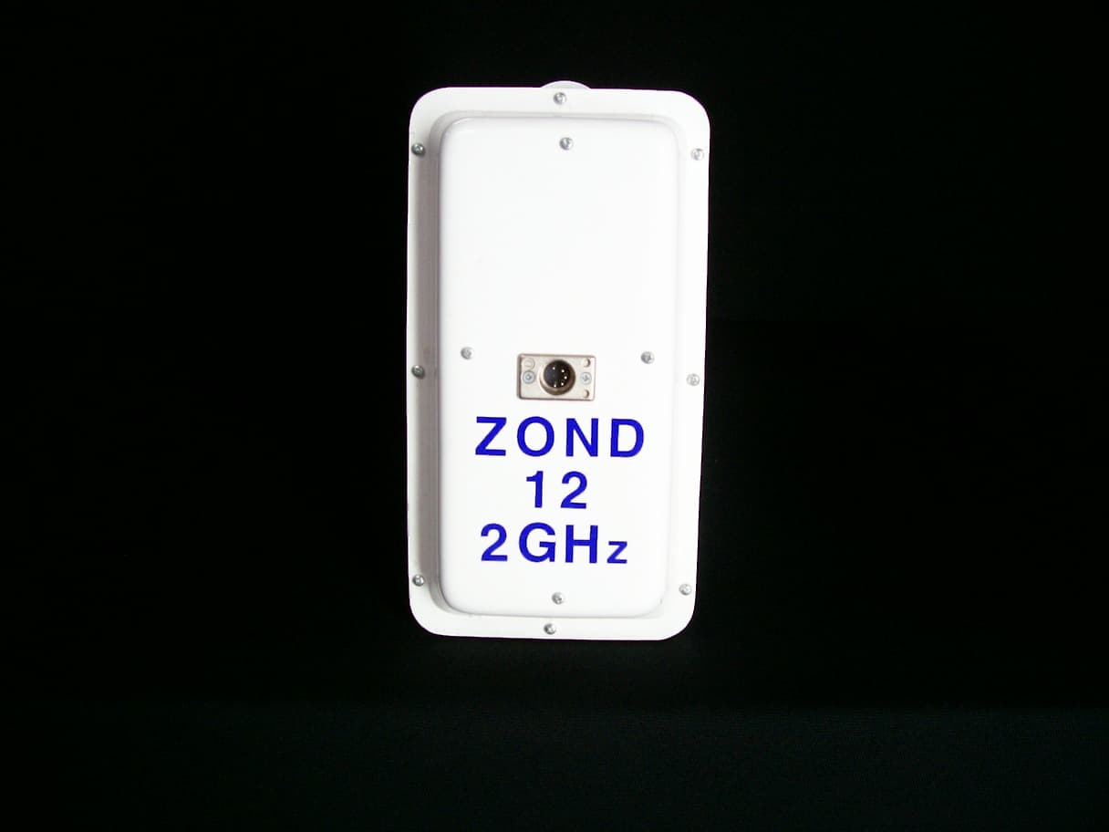
Click to zoom
Application Details
- Equipment Class
- UWB - Ultra Wideband Transmitter
- Date of Grant
- Nov 18, 2007
- Application Purpose
- Original Equipment
- Date of Application
- Sep 30, 2007
- Equipment Note
- ZOND 12 2GHz Ground Penetrating Antenna
- Frequency Range
- 551.85000000 - 1794.35000000
- Company
- Accurate Locators Inc.
- Country
- United States
Documents & Files
Document Text
Text extracted from the exhibit documents filed with the FCC. Open a document above to read the original.
Users Manual
RAD~ "Zond-12es' PhonelFax (+371)-7141041 E-mail:[email protected] www.radsys.1~ Systems, Inc. Georadar USER'S MANUAL Riga, 2007 Lomonosova Str. 1, B-406, Riga LV-1019, Latvia Web: FCC Notice (for U.S. Customers): This device complies with part 15 of the FCC Rules: Operation is subject to the following conditions: 1. This device many not cause harmful interference, and 2. This device must accept any interference received, including interference that may cause undesired operation Warning: Changes or modifications to this unit not expressly approved by the party responsible for compliance could void the user’s authority to operate the equipment. Operation of this device is restricted to law enforcement, fire and rescue officials, scientific research institutes, commercial mining companies, and construction companies. Operation by any other party is a violation of 47 U.S.C. § 301 and could subject the operator to serious legal penalties. Coordination Requirements. (a) UWB imaging systems require coordination through the FCC before the equipment may be used. The operator shall comply with any constraints on equipment usage resulting from this coordination. (b) The users of UWB imaging devices shall supply detailed operational areas to the FCC Office of Engineering and Technology who shall coordinate this information with the Federal Government through the National Telecommunications and Information Administration. The information provided by the UWB operator shall include the name, address and other pertinent contact information of the user, the desired geographical area of operation, and the FCC ID number and other nomenclature of the UWB device. This material shall be submitted to the following address: Frequency Coordination Branch., OET Federal Communications Commission 445 12th Street, SW Washington, D.C. 20554 ATTN: UWB Coordination (d) Users of authorized, coordinated UWB systems may transfer them to other qualified users and to different locations upon coordination of change of ownership or location to the FCC and coordination with existing authorized operations. (e) The NTIA/FCC coordination report shall include any needed constraints that apply to day-to- day operations. Such constraints could specify prohibited areas of operations or areas located near authorized radio stations for which additional coordination is required before operation of the UWB equipment. If additional local coordination is required, a local coordination contact will be provided. (f) The coordination of routine UWB operations shall not take longer than 15 business days from the receipt of the coordination request by NTIA. Special temporary operations may be handled with an expedited turn-around time when circumstances warrant. The operation of UWB systems in emergency situations involving the safety of life or property may occur without coordination provided a notification procedure, similar to that contained in CFR47 Section 2.405(a)-(e), is followed by the UWB equipment user. "Zond-12e" "Zond-12e" Fig.14. Fig.1. 38-75- Fig.la). "Zond-12e" IBM- 1 1 1 10/100BaseT. TCPIIP 10,5 "Zond-12e". GHz GHz 1. INTRODUCTION 1.1. Purpose and the Field of Application. The georadar is the facilities for subsurface profiling purposed to obtain continuous profiles of subsurface structure of ground along the survey line. The principal fields of application are: mapping of the surface of bed-rock under the layer of mellow deposits; search of pipes and cables; glaciology; archeology and criminal law; search of cavities in; mapping of water table in sand deposits; mapping of bottom and bottom deposits of fresh water reservoirs; mapping of river paleobeds; searching of sites of burring of industrial wastes, etc. 1.2. General Description. The georadar in operating condition consists of four units: the control unit, the Notebook computer, the antenna and the battery (see Fig 1). The computer is mounted on the special platform on top of the control unit. They are connected by the cable with pin specification shown on The control unit is operated by direct current of voltage12 V supplied by the battery or a regulated rectifier. The antenna and the control unit are connected by the antenna cable as it is shown on If antenna has two connectors (antenna 150 MHz) they are marked with red and blue labels (see Using of two separated antennas for transmitting and receiving are shown on Fig. lb where transmitting antenna is connected to blue connector but receiving antenna to red one. Description of controls and connectors of Control Unit is on Fig.2. Hereafter are presented brief specifications of different units of the georadar. Computer. There can be applied in composition of the georadar any compatible Notebook computer operating in Windows 98 2000 Me XP, equipped with Ethernet card Information exchange between the computer and the control unit is performed according to protocol as between two peer network elements. The computer performs the following functions: control of operational modes of the georadar, data acquisition, processing and displaying. Battery. Any power supply providing direct current voltage from to 13 V at current up to 0.8 A. Upon delivery the georadar is supplied with the sealed lead battery with voltage 12 V of capacity 7 Ah, the power cord, and the automatic charger. Control unit. The circuit diagram of the control unit is shown in Fig.2. Brief description of controls of the control unit is presented on page 9. Packaging of the unit is shown in Fig. 13. Antenna. Antennas of three types are applied in the georadar High frequency shielded antennas 100, 300, 500, 900 MHz, 1.5 and unshielded 2 antenna are similar and differ only in dimensions. Theese antennas are intended for operating mostly in contact with the groung. The low frequency antenna 38-75 -150 MHz is of the dipole type with replaced dipoles for operation at frequencies 150, 75 and 38 MHz. That antenna may be used in isolation from the ground at distance 0.15…
Text truncated - open the document above for the full version.
Users Manual
7 To control unit Fig. 3b. Attaching of survey wheel to shielded antenna. Antenna unit 300,500,900 Mhz or 1.5 Ghz L L Fig. 3c. Attaching of handle, 20 m cable and survey L wheel to shielded antenna. "W.5 ..I;.' ,. -. - - 5% * .:-*-?.', ;. i.7 1- $ : -- .:. ,I I.' ,. .e,(- \.'- : ? -: .. , . . ' ..,a '-I . .I -. . . ., . . $I., I' . ,- . . @ --. Fig. 14. Pin specification of cable between control unit and computer r
Cover Letter(s)
09/20/07 Nemko Canada Inc 303 River Road Ottawa, Ontario, Canada K1V 1H2 Attn: Director of Certification Authority to Act as Agent On our behalf, I appoint Nemko Canada Inc, 303 River Road, Ottawa, Ontario, Canada K1V 1H2, to act as our agent in the preparation of this application for equipment certification. I certify that submitted documents properly describe the device or system for which equipment certification is sought. I also certify that each unit manufactured, imported or marketed, as defined in the Federal Communications Commission’s regulations will have affixed to it a label identical to that submitted for approval with this application. For instances where our authorized agent signs the application for certification on our behalf, I acknowledge that all responsibility for complying with the terms and conditions for certification, as specified by Nemko Canada Inc, still resides with Accurate Locators Inc. 1383 2nd Avenue, Gold Hill Oregon, 97525 Dated this 20TH Day of September 20 07 Agency agreement expiration date: September 20, 2008 By: Wayne Good Signature Printed Title: President On behalf of : Accurate Locators, Inc Telephone: 775-751-6931
Cover Letter(s)
09/20/07 Equipment Authorisation Division Federal Communications Commission 7435 Oakland Mills Road Columbia, MD 21046 FCC ID: VNU-2GHZANT Product Name: ZOND 12 2GHz Ground Penetrating Antenna Request for Confidentiality Pursuant to Sections 0.457 and 0.459 of the commissions rules, we hereby request that the following documents be held confidential: (List here the documents for which you are seeking confidentiality – for example ...) • Schematics/ Parts List • Block diagram • Operational description These materials contain trade secrets and proprietary information and are not customarily released to the public. The public disclosure of this information might be harmful to the company and provide unjustified benefits to our competitors. Dated this 20th Day of September 20 07 By: Wayne Good Signature Printed Title: President On behalf of : Accurate Locators, Inc Telephone: 775-751-6931
Test Report
www.nemko.com FCC Part 15 Subpart F, August 2007 Test Report: 86438TRFWL Applicant: Accurate Locators 1383 2nd Ave Gold Hill, Oregon 97525 Apparatus: Zond Ground Penetrating Radar FCC ID: VNU2GHZANT In Accordance With: FCC Part 15 Subpart F Ultra-Wideband Operation Tested By: Nemko Canada Inc. 303 River Road Ottawa, Ontario K1V 1H2 Authorized By: Roman Kuleba, Wireless Specialist Date: October 1, 2007 Total Number of Pages: 16 Nemko Canada Inc. REPORT SUMMARY Report Number: 86438TRFWL FCC ID: VNU2GHZANT Specification: FCC Part 15 Subpart F Page 2 of 16 Report Summary These tests were conducted on a sample of the equipment for the purpose of demonstrating compliance with Part 15, Subpart F. Radiated tests were conducted in accordance with ANSI C63.4-2003. Radiated emissions are made on an open area test site. A description of the test facility is on file with the FCC. The assessment summary is as follows: Apparatus Assessed: Zond Ground Penetrating Radar Specification: FCC Part 15 Subpart F Compliance Status: Complies Exclusions: None Non-compliances: None Report Release History: Original Release Author: Jason Nixon, Telecom Specialist Note that the results contained in this report relate only to the items tested and were obtained in the period between the date of initial receipt of samples and the date of issue of the report. This test report has been completed in accordance with the requirements of ISO/IEC 17025. Nemko Canada Inc. authorizes the applicant to reproduce this report provided it is reproduced in its entirety and for use by the company’s employees only. Any use which a third party makes of this report, or any reliance on or decisions to be made based on it, are the responsibility of such third parties. Nemko Canada Inc. accepts no responsibility for damages, if any, suffered by any third party as a result of decisions made or actions based on this report. Nemko Canada Inc. REPORT SUMMARY Report Number: 86438TRFWL FCC ID: VNU2GHZANT Specification: FCC Part 15 Subpart F Page 3 of 16 TABLE OF CONTENTS Report Summary......................................................................................................................................... 2 Section 1 : Equipment Under Test............................................................................................................. 4 1.1 Product Identification .................................................................................................................................4 1.2 Samples Submitted for Assessment............................................................................................................4 1.3 Theory of Operation ...................................................................................................................................4 1.4 Technical Specifications of the EUT ..........................................................................................................5 1.5 Block Diagram of the EUT.........................................................................................................................5 Section 2 : Test Conditions......................................................................................................................... 6 2.1 Specifications .............................................................................................................................................6 2.2 Deviations From Laboratory Test Procedures ............................................................................................6 2.3 Test Environment .......................................................................................................................................6 2.4 Test Equipment...........................................................................................................................................6 2.5 Measurement Uncertainty...........................................................................................................................6 Section 3 : Observations ............................................................................................................................. 7 3.1 Modifications Performed During Assessment ............................................................................................7 3.2 Record Of Technical Judgements ...............................................................................................................7 3.3 EUT Parameters Affecting Compliance .....................................................................................................7 3.4 Test Deleted................................................................................................................................................7 3.5 Additional Observations .............................................................................................................................7 Section 4 : Results Summary ..................................................................................................................... 8 4.1 FCC Part 15 Subpart F : Test Results .........................................................................................................9 Appendix A : Test Results ........................................................................................................................ 10 Clause 15.509(a) UWB Bandwidth .....................................................................................................................10 Clause 15.509(d) Radiated Emissions .................................................................................................................11 Clause 15.509(e) Additional Radiated Emissions................................................................................................13 Clause 15.509(f) Emissions of f m above 1GHz ...................................................................................................14 Appendix B : Setup Photographs…
Text truncated - open the document above for the full version.
Test Setup Photos
Spurious Emissions Setup:
Contact Information
Applicant
Wayne Thomas Good(President)
Technical Contact
Accurate Locators, Inc.Jason Warren Lieber
[email protected]541-855-1590
1383 2nd Avenue · Gold Hil, Oregon · United States
Non-Technical Contact
Accurate Locators, Inc.Susan Good
[email protected]775-751-6931
Test Firm
Nemko Canada Inc. (Ottawa)Charles Neal
Technical Specifications
| # | Rule Parts | Frequency Range | Power Output |
|---|---|---|---|
| 1 | 15F | 551.85 MHz - 1.79 GHz | - |