VOWCGUHG20100FLO REPEATER
MIER COMUNICACIONES S.A.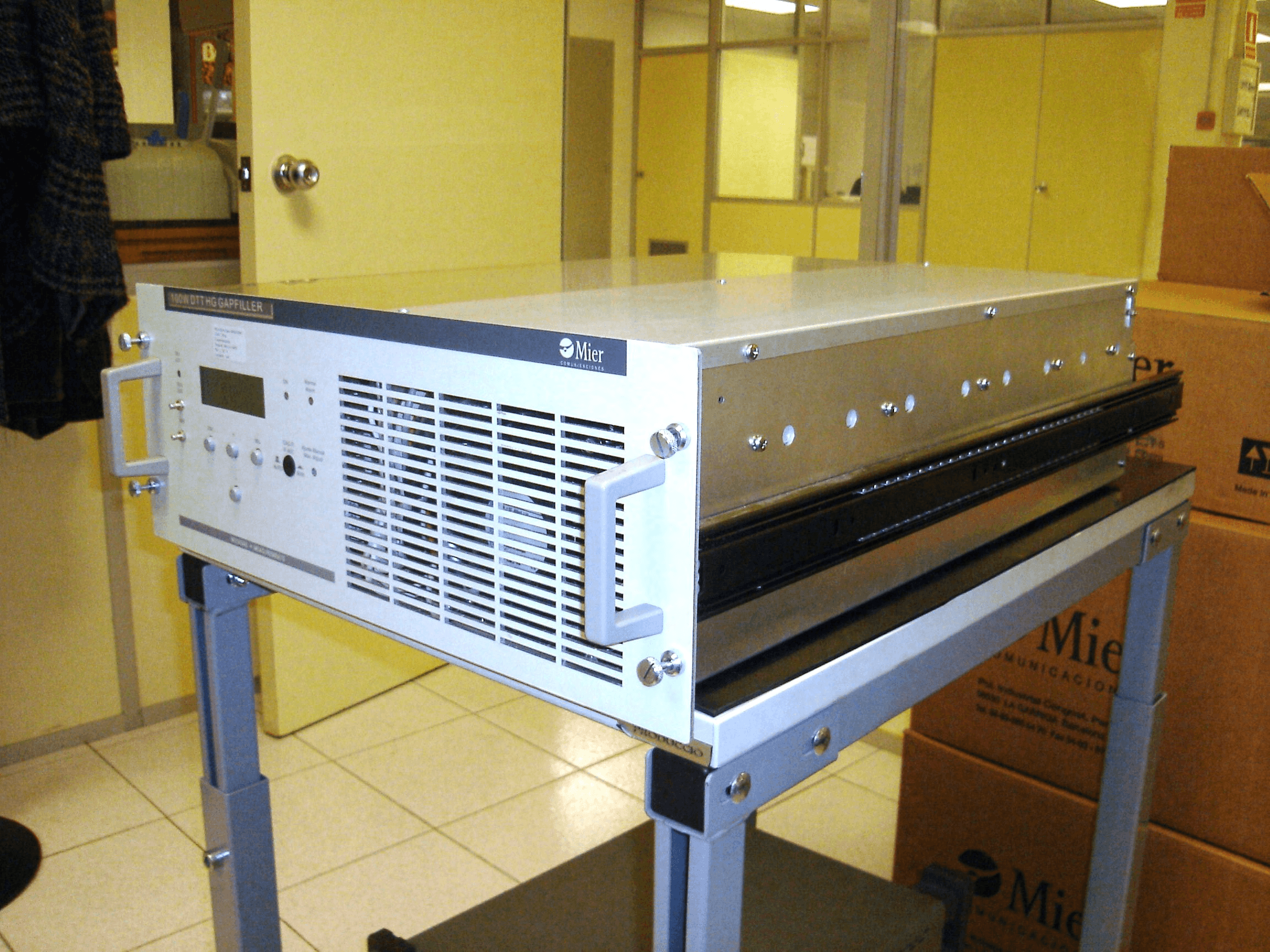
Click to zoom
Application Details
- Equipment Class
- TNB - Licensed Non-Broadcast Station Transmitter
- Date of Grant
- Feb 21, 2008
- Application Purpose
- Original Equipment
- Date of Application
- Feb 20, 2008
- Equipment Note
- FLO REPEATER
- Frequency Range
- 719.00000000 - 719.00000000
- Company
- MIER COMUNICACIONES S.A.
- Country
- Spain
Documents & Files
Document Text
Text extracted from the exhibit documents filed with the FCC. Open a document above to read the original.
Users Manual
MIER COMUNICACIONES S.A. Polígono Industrial Congost - Par. 4S - 08530 - La Garriga - (BARCELONA) - SPAIN Tel. +34 (93) 860 54 70 - Fax. +34 (93) 871 72 30 www.mier.es USER MANUAL F LO Repeater Gap-fillers CGU20-50-100 Wrms © MIER COMUNICACIONES, S.A. All rights reserved. T his document and all information contained in it are property of MIER COMUNICACIONES, S.A. and can be pending of patent assigning or it might be already assigned. It must not be used for trading neither copied, advertised, reproduced, recorded on any recording system nor transmitted in any case using any way (electronic, mechanic, photocopy or something else), totally or partially, without a previous written consent of MIER COMUNICACIONES, S.A. FLO Repeater CGU20-50-100W HG Doc: 47N0208 Edition: 1 Date: 04/10/2007 TABLE OF CONTENTS TABLE OF CONTENTS 2/87 1. SAFETY INSTRUCTIONS ................................ . . ................................................ 7 1.1. INTRODUCTION ................................................................................................. 7 1.2. GENERAL RECOMMENDATIONS ......................... ............................................ 7 1.3. ELECTRIC SHOCK HAZARD ............................................................................. 9 1.4. ELECTROSTATIC DISCHARGE HAZARD ......................................................... 9 1.5. RF HAZARDS ...................................... .............................................................. 10 1.6. FIRE RISK ......................................................................................................... 10 1.7. DIRECTIVE 1999/5/EC (R&TTE) ..................... ................................................. 12 1.8. FCC RULE PARTS 15.21 AND 15.103 ........................................................................ 12 2. INSTALLATION AND PUTTING INTO OPERATION ....................................... 13 2.1. ENVIRONMENTAL SPECIFICATIONS ............................................................. 13 2.2. RACK MOUNTING ............................................................................................ 13 2.3. UNIT CONNECTORS ........................................................................................ 14 2.3.1. INPUT CONNECTOR ................................................................................. 14 2.3.2. OUTPUT CONNECTOR ............................................................................. 16 2.3.3. SAMPLE CONNECTORS ........................................................................... 16 2.3.4. GROUND AND POWER SUPPLY CABLES ............................................... 20 2.4. START-UP OPERATION ................................................................................... 21 2.5. MAINTENANCE RECOMMENDATIONS .......................................................... 21 3. INTELLIGENT HIGH GAIN ON-CHANNEL REPEATER (HGOCR-I) ............... 23 3.1. INTRODUCTION ............................................................................................... 23 3.2. OCR, HGOCR & HGOCR-I ............................................................................... 24 3.3. HGOCR-I PHILOSOPHY ................................................................................... 25 3.4. OPERATING EXAMPLES ................................................................................. 27 3.5. HGOCR-I CONFIGURABLE PARAMETERS THROUGH THE FRONT PANEL30 3.5.1. “SMART AGC” MENU: ................................................................................ 30 3.5.2. ”IF STAGES” MENU: .................................................................................. 32 3.5.3. “ECHO CANCELLER” MENU: .................................................................... 33 4. GENERAL DESCRIPTION ............................................................................... 34 5. UNIT COMPOSITION ........................................................................................ 35 6. MECHANICAL DESCRIPTION ......................................................................... 36 FLO Repeater CGU20-50-100W HG Doc: 47N0208 Edition: 1 Date: 04/10/2007 TABLE OF CONTENTS TABLE OF CONTENTS 3/87 6.1. FRONT PANEL ................................................................................................. 38 6.2. BACK PANEL .................................... . ............................................................... 40 6.3. INTERNAL PARTS SITUATION ....................... ................................................. 41 6.4. RF ZONE BOARDS SITUATION ....................................................................... 42 6.4.1. TEMPERATURE PROBES SITUATION ..................................................... 43 6.5. INTERNAL LIDS .................................. .............................................................. 44 6.6. UNIT RAILS ....................................................................................................... 47 7. ELECTRONIC DESCRIPTION .............................. ............................................ 48 7.1. SIGNAL PATH DESCRIPTION ........................ ................................................. 50 7.2. POWER SUPPLY DISTRIBUTION .................................................................... 52 7.3. CONTROL AND MEASUREMENTS ................................................................. 53 8. TECHNICAL SPECIFICATIONS ............................ ........................................... 55 9. CONTROL SOFTWARE DESCRIPTION .......................................................... 60 9.1. DISPLAY AND KEYBOARD .............................................................................. 60 9.1.1. INFORMATION IN THE DISPLAY .............................................................. 60 9.1.2. KEYBOARD NAVIGATION .......................... ............................................... 61 9.2. USER INTERFACE MENU ...............................................................…
Text truncated - open the document above for the full version.
Cover Letter(s)
Applicant: Mier Comunicaciones S.A. FCC.ID : VOW-CGUHG20100 3 of October 2007 Request of Confidentiality Federal Communications Commission Authorization and Evaluation Division Re: Request of Confidentiality Pursuant to Sections 0.457 and 0.459 of the Commission’s Rules, the Applicant hereby requests confidential treatment of information accompanying this Application as outlined below: All schematics All parts lists The above materials contain trade secrets and proprietary information not customarily released to the public. The public disclosure of these matters might be harmful to the Applicant and provide unjustified benefits to its competitors. The Applicant understands that pursuant to Rule 0.457, disclosure of this Application and all accompanying documentation will not be made before the date of the Grant for this Application. Mier Comunicaciones S.A. Nicasio Sánchez Quality Manager
ID Label/Location Info
DC B A A C B D 2 3 4 5 3 4 5 2 1 COMUN I CACI O NES Mod.Ref. Mod.DateName DateName Drawn Checked Approved. Codigo/ Material: Acabado: Denominacion / Version Description Code Material: Finish: Hoja n° Sheet n° Escala Scale 38N1040-10 ETIQUETA FCC FLO REPEATER 100W FCC LABEL FLO REPEATER 100W 16 mm rsuarez 27/09/07 LOCALIZACION ETIQUETA LOCATION LABEL ETIQUETA ADHESIVA FONDO BLANCO TEXTO NEGRO ADHESIVE LABEL WHITE BACKGROUND BLACK TEXT 10 20/02/08 Texto FCC Rsuarez Mier Comunicaciones,S.A. FLO REPEATER 100W FCC ID: VOW-CGUHG20100 120 mm This device complies with Part 15 of the FCC Rules. Operation is subject to the following two conditions: (1) this device may not cause harmful interference, and (2) this device must accept any interference received, including interference that may cause undesired operation
Internal Photos
80A0847 -A 80A0847 -B 80A0780 - A 80A0780 - B 80A0780 - A 80A0780 - B THE OTHER SIDE OF THESE BOARDS IS 100% COPPER, IN C ONTACT WITH THE ALUMINIUM ENCLOSURE 84S0826 84S0827 84S0829 ( interconnect strip ) 84S0843 Output Coupler (Mech.) 84S0826 84S0827 84S0829 ( interconnect strip ) 84S0858 (output (output interconnect strip) 84A0507 84A0518 84N0830 2 x 84N0812 84S0859 (input interconnect strip ) strip ) Commercial Part LDU-60M 25Wps LDMOS module from Commercial Part LDU-400M 70Wrms LDMOS module from 25Wps LDMOS module from RICHARDSON ELECTRONICS. 70Wrms LDMOS module from RICHARDSON ELECTRONICS. 80A0715-A 80A0715-B 80S0657-A 80S0657-B 84A0393-A 84A0393-B 80A0779-A 80A0779-B 84S0783-A 84S0783-B 84A0270-A 84A0270-B 84N0506-A 84N0506-B 80S0688-A 80S0688-B 84A0180 80A0554-B 80A0554-A 80A0508 80A0508 80A0501 THE OTHER SIDE OF THESE BOARDS IS 100% COPPER, IN C ONTACT WITH THE ALUMINIUM ENCLOSURE
Operational Description
MIER COMUNICACIONES S.A. Polígono Industrial Congost - Par. 4S - 08530 - La Garriga - (BARCELONA) - SPAIN Tel. +34 (93) 860 54 70 - Fax. +34 (93) 871 72 30 www.mier.es OPERATIONAL DESCRIPTION FLO Repeater CGU-20-50-100 Wrms © MIER COMUNICACIONES, S.A. All rights reserved. This document and all information contained in it are property of MIER COMUNICACIONES, S.A. and can be pending of patent assigning or it might be already assigned. It must not be used for trading neither copied, advertised, reproduced, recorded on any recording system nor transmitted in any case using any way (electronic, mechanic, photocopy or something else), totally or partially, without a previous written consent of MIER COMUNICACIONES, S.A. FLO Repeater CGU20-50-100W HG OPERATIONALDESCRIPTION Edition: 1 Date: 16/10/2007 TABLE OF CONTENTS TABLE OF CONTENTS 2/36 1. INTELLIGENT HIGH GAIN ON-CHANNEL REPEATER (HGOCR-I) ................. 5 1.1. INTRODUCTION ................................................................................................. 5 1.2. OCR, HGOCR & HGOCR-I ................................................................................. 6 1.3. HGOCR-I PHILOSOPHY ..................................................................................... 7 1.4. OPERATING EXAMPLES ................................................................................... 9 1.5. HGOCR-I CONFIGURABLE PARAMETERS THROUGH THE FRONT PANEL12 1.5.1. “SMART AGC” MENU: ................................................................................ 12 1.5.2. ”IF STAGES” MENU: .................................................................................. 14 1.5.3. “ECHO CANCELLER” MENU: .................................................................... 15 2. GENERAL DESCRIPTION ............................................................................... 16 3. UNIT COMPOSITION ........................................................................................ 17 4. MECHANICAL DESCRIPTION ......................................................................... 18 4.1. FRONT PANEL ................................................................................................. 20 4.2. BACK PANEL .................................................................................................... 22 4.3. INTERNAL PARTS SITUATION ........................................................................ 23 4.4. RF ZONE BOARDS SITUATION ....................................................................... 24 4.4.1. TEMPERATURE PROBES SITUATION ..................................................... 25 4.5. INTERNAL LIDS ................................................................................................ 26 4.6. UNIT RAILS ....................................................................................................... 29 5. ELECTRONIC DESCRIPTION .......................................................................... 30 5.1. SIGNAL PATH DESCRIPTION ......................................................................... 32 5.2. POWER SUPPLY DISTRIBUTION .................................................................... 34 5.3. CONTROL AND MEASUREMENTS ................................................................. 35 FLO Repeater CGU20-50-100W HG OPERATIONALDESCRIPTION Edition: 1 Date: 16/10/2007 LIST OF FIGURES 3/36 Figure 6.- Front panel elements. ........................................................................................................... 20 Figure 7.- Front view. Downside. ........................................................................................................... 21 Figure 8. Back panel configuration ........................................................................................................ 22 Figure 9.- Internal parts situation. .......................................................................................................... 23 Figure 10.- RF slots nomenclature. ....................................................................................................... 24 Figure 11.- Temperature probes situation. ............................................................................................ 25 Figure 12.- RF interconnection internal panel. ...................................................................................... 26 Figure 13.- RF Area lid. ......................................................................................................................... 28 Figure 14.- Extraction of gap-filler unit from rack rails. .......................................................................... 29 Figure 15.- Complete Gap-filler unit block diagram ............................................................................... 31 Figure 16.- RF Signal block diagram. .................................................................................................... 33 Figure 17.- Power supply distribution diagram. ..................................................................................... 34 Figure 18.- Control and measurement block diagram. .......................................................................... 36 FLO Repeater CGU20-50-100W HG OPERATIONALDESCRIPTION Edition: 1 Date: 16/10/2007 INTELLIGENT HIGH GAIN ON-CHANNEL REPEATER (HGOCR-I) 4/36 Table 2.- Modules and boards list for the CGU20-50-100W HG FLO. ................................................. 17 Table 3.- Control and measurements signals brief. .............................................................................. 35 FLO Repeater CGU20-50-100W HG OPERATIONALDESCRIPTION Edition: 1 Date: 16/10/2007 INTELLIGENT HIGH GAIN ON-CHANNEL REPEATER (HGOCR-I) 5/36 1. INTELLIGENT HIGH GAIN ON-CHANNEL REPEATER (HGOCR-I) 1.1. INTRODUCTION Intelligent High Gain On-Channel Repeaters (hereinafter HGOCR-I) are the new solution for SFN repeaters designed and manufactured by MIER COMUNICACIONES. Traditional on-channel repeaters require to know or …
Text truncated - open the document above for the full version.
Test Report
This document will not be reproduced otherwise than in full. Reports will only be legally valid with original signature or attested copies. This is the first page of the document, which consists of 16 pages. Bellaterra : January 28, 2008 File number: 07/32011897-M1 Petitioner’s reference: MIER COMUNICACIONES, S.A P.I. CONGOST, PARC. 45 08530 LA GARRIGA (SPAIN) On its behalf: Nicasio Sanchez This file replaces to 07/32011897. Modifications performed: Section 4.0. Results. TEST REPORT TEST REQUESTED Tests according to FCC CFR 47 Part 2 and Part 27. This report contains all the required data for certification FLO repeater system for FLO signal broadcasting. The data presented was taken from tests performed on a production repeater system model FLO Repeater 100Wrms having an 100Wrms nominal rated output power, tuned to operate on a fixed 716-722MHz (6MHz BW) channel and using a mask filter. Mier Comunicaciones, S.A wishes to certify its FLO Repeater with two different output mask filters. For this reason, the Ocuppied Bandwidth test has been performed with two different mask filters. INDEX 1.0 EQUIPMENT RECEIVED AND TESTED 1.1 Test configuration 1.2 Auxiliary and control equipment 2.0 TESTING PROCEDURE 3.0 IDENTIFICATION PICTURES 4.0 RESULTS 1.0 EQUIPMENT RECEIVED AND TESTED FLO repeater, brand Mier Comunicaciones, model FLO repeater 100Wrms s/n:612280 Test product reception: 18/9/2007 Test initial date: 18/9/2007 Test final date: 25/9/2007 1.1 Test configuration Power supply: 120V 60Hz Set-up: On table File Nº 07/32011897-M1 Page Nº 2/2 Test exercise: Transmitting to the maximum output power on a resistive load 1.2 Auxiliary and control equipment -Input filter, brand Telmec, channel 55, UHF band, s/n: 07/00/0376/02/001, p/n: PBN38/12-6c/n -Vector signal generator, brand Agilent, model E4458G, s/n MY45096106 -GPS Receiver, brand Mier Comunicaciones, s/n 75 -Output filter, brand ERI Electronics Research, p/n: CF528-055, s/n: 01168-031306-5 -Output filter, brand Mier Comunicaciones, model 840583-00, s/n: 17 -Attenuator, brand R&S RBU 30 p/n:100.8654.37, calibration date: 9/11/2006 -Attenuator, brand Weinschel Corp DC-18GHz 10dB 100W, calibration date: 9/11/2006 -RF Terminator, model 5600 s/n:--- -Directional coupler brand Narda model 3001-30 (30dB) s/n: 20938, calibration date: 16/2/2007 2.0 MEASURING EQUIPMENT USED RF Power Output -Boonton 4300 RF power meter s/n 94805Efm, calibration date: 17/11/2006 -Power sensor model 51013 s/n 04-665106, calibration date: 17/11/2006 Ocuppied Bandwidth -Emi Receiver brand: HP model 8546A s/n: 3710A00389, calibration date: 30/8/2006 -FSP ROHDE&SCHWARZ SPECTR.ANALYZER 093.4495K03 s/n: 100015, calibration date: 08/11/2006 Spurious Emissions at Antenna Terminals - Emi Receiver brand: HP model 8546A s/n: 3710A00389, calibration date: 30/8/2006 Field Strenght of Spurious Radiation - Semianechoic chamber EUROSHIELD model TC2 TEST CHAMBER - Spectrum analyser HP model 8566B s/n: 3138A08001, calibration date: 16/4/2007 - Preselector HP model 85685A s/n: 3506A01519, calibration date: 16/4/2007 - Horn antenna EMCO model 3115 s/n: 4240, calibration date: 28/9/2006 - Attenuator 3dB NARDA model 773-3 s/n: 111, calibration date: 16/1/2007 - Directional coupler: NARDA 3001-30 (30 dB) s/n: 20938, calibration date: - Bilogoperiodic antenna MESS-ELEKTRONIK model VULB 9165 s/n: 2009, calibration date: 8/2/2007 - Turntable HD model DS 430 - Antenna tower HD model MA 240T s/n: 240/458 - Computer system brand:HP model P2190N s/n: FR10717868 - Emi Receiver brand: HP model 8546A s/n: 3710A00389, calibration date: 30/8/2006 - Pre-Amplifier brand: HP model 8449B OPT H02 s/n: 3008A00739 - Signal Generator brand: HP model HP 8648B s/n: 3642U01234, calibration date: 20/8/2007 Frequency stability - Emi Receiver brand: HP model 8546A s/n: 3710A00389, calibration date: 30/8/2006 - Climatic chamber Dycometal model CM-40/480 s/n: 1642/02, calibration date: 15/12/2006 - Spitzenberger + Spies EMV E 1000/PAS, calibration date: 5/12/2006 - Computer system HP model D4541N s/n: FR71084499 File Nº 07/32011897-M1 Page Nº 3/3 3.0 IDENTIFICATION PICTURES Occupied BW Spurious at Antenna Terminals. Frequency Stability Field Strengh of Spurious Emissions File Nº 07/32011897-M1 Page Nº 4/4 4.0 RESULTS 4.1 RF Power output Nominal output power: 100 watts Method of Measurement: According to FCC 2.1046 (a) (c) The repeater was operated into a dummy load of substantially zero reactive with a resistance equal to the transmission line characteristic impedance. Average power was indirectly measured using a Boontom 4300 RF power meter by means of an external directional coupler which coupling factor was previously determined. It is recorded in different amplification steps the output power displayed by the power meter and by the DUT. Figure 3.1-1 shows the test setup A) Measurements at the output mask filter (external coupler) Amplifier Power meter displayed (dBm) DUT level displayed (dB) Coupler Correction factor (dB) Attenuator factor (dB) Power output corrected (dBm) 1045 -12,34 0 29,3 30,58 47,54 950 -15,98 -3,3 29,3 30,58 43,90 900 -18,54 -5,7 29,3 30,58 41,34 850 -21,55 -8,4 29,3 30,58 38,33 800 -25,24 Low (<-10) 29,3 30,58 34,64 FLO generator Input Filter DUT Output Filter Coupler Load Attenuator Power sensor Power meter Sample File Nº 07/32011897-M1 Page Nº 5/5 B) Measurements at the sample signal (internal coupler) Amplifier Power meter displayed (dBm) DUT level displayed (dB) Correction factor (dB) Power output corrected (dBm) 1045 18,45 0 35,45 53,90 850 10,64 -8,3 35,45 46,09 4.2 Ocuppied Bandwidth/Emissions Method of Measurement: According to FCC 2.1049 (h), 2.202 (a), 2.1047, 27.53 (f) Type of modulation: Media FLO (COFDM) QPSK/16QAM The repeater is operated into a attenuators (30dB). The output signal is conducted directly to the spectrum analyzer input. Measurements in the channel limit, channel limit+100kHz and channel limit+13MHz are performed to check the occupied bandwidth and modulation charac…
Text truncated - open the document above for the full version.
Test Report
This document will not be reproduced otherwise than in full. Reports will only be legally valid with original signature or attested copies. This is the first page of the document, which consists of 16 pages. Bellaterra : February 25, 2008 File number: 07/32011897-M2 Petitioner’s reference: MIER COMUNICACIONES, S.A P.I. CONGOST, PARC. 45 08530 LA GARRIGA (SPAIN) On its behalf: Nicasio Sanchez This file replaces to 07/32011897-M1. Modifications performed: Section 4.0. Results. Added cable attenuation correction factors and modified internal coupler correction factor. TEST REPORT TEST REQUESTED Tests according to FCC CFR 47 Part 2 and Part 27. This report contains all the required data for certification FLO repeater system for FLO signal broadcasting. The data presented was taken from tests performed on a production repeater system model FLO Repeater 100Wrms having an 100Wrms nominal rated output power, tuned to operate on a fixed 716-722MHz (6MHz BW) channel and using a mask filter. Mier Comunicaciones, S.A wishes to certify its FLO Repeater with two different output mask filters. For this reason, the Ocuppied Bandwidth test has been performed with two different mask filters. INDEX 1.0 EQUIPMENT RECEIVED AND TESTED 1.1 Test configuration 1.2 Auxiliary and control equipment 2.0 TESTING PROCEDURE 3.0 IDENTIFICATION PICTURES 4.0 RESULTS 1.0 EQUIPMENT RECEIVED AND TESTED FLO repeater, brand Mier Comunicaciones, model FLO repeater 100Wrms s/n:612280 Test product reception: 18/9/2007 Test initial date: 18/9/2007 Test final date: 21/1/2008 1.1 Test configuration Power supply: 120V 60Hz File Nº 07/32011897-M2 Page Nº 2/2 Set-up: On table Test exercise: Transmitting to the maximum output power on a resistive load 1.2 Auxiliary and control equipment -Input filter, brand Telmec, channel 55, UHF band, s/n: 07/00/0376/02/001, p/n: PBN38/12-6c/n -Vector signal generator, brand Agilent, model E4458G, s/n MY45096106 -GPS Receiver, brand Mier Comunicaciones, s/n 75 -Output filter, brand ERI Electronics Research, p/n: CF528-055, s/n: 01168-031306-5 -Output filter, brand Mier Comunicaciones, model 840583-00, s/n: 17 -Attenuator, brand R&S RBU 30 p/n:100.8654.37, calibration date: 9/11/2006 -Attenuator, brand Weinschel Corp DC-18GHz 10dB 100W, calibration date: 9/11/2006 -RF Terminator, model 5600 s/n:--- -Directional coupler brand Narda model 3001-30 (30dB) s/n: 20938, calibration date: 16/2/2007 2.0 MEASURING EQUIPMENT USED RF Power Output -Boonton 4300 RF power meter s/n 94805Efm, calibration date: 17/11/2006 -Power sensor model 51013 s/n 04-665106, calibration date: 17/11/2006 Ocuppied Bandwidth -Emi Receiver brand: HP model 8546A s/n: 3710A00389, calibration date: 30/8/2006 -FSP ROHDE&SCHWARZ SPECTR.ANALYZER 093.4495K03 s/n: 100015, calibration date: 08/11/2006 Spurious Emissions at Antenna Terminals - Emi Receiver brand: HP model 8546A s/n: 3710A00389, calibration date: 30/8/2006 Field Strenght of Spurious Radiation - Semianechoic chamber EUROSHIELD model TC2 TEST CHAMBER - Spectrum analyser HP model 8566B s/n: 3138A08001, calibration date: 16/4/2007 - Preselector HP model 85685A s/n: 3506A01519, calibration date: 16/4/2007 - Horn antenna EMCO model 3115 s/n: 4240, calibration date: 28/9/2006 - Attenuator 3dB NARDA model 773-3 s/n: 111, calibration date: 16/1/2007 - Directional coupler: NARDA 3001-30 (30 dB) s/n: 20938, calibration date: - Bilogoperiodic antenna MESS-ELEKTRONIK model VULB 9165 s/n: 2009, calibration date: 8/2/2007 - Turntable HD model DS 430 - Antenna tower HD model MA 240T s/n: 240/458 - Computer system brand:HP model P2190N s/n: FR10717868 - Emi Receiver brand: HP model 8546A s/n: 3710A00389, calibration date: 30/8/2006 - Pre-Amplifier brand: HP model 8449B OPT H02 s/n: 3008A00739 - Signal Generator brand: HP model HP 8648B s/n: 3642U01234, calibration date: 20/8/2007 Frequency stability - Emi Receiver brand: HP model 8546A s/n: 3710A00389, calibration date: 30/8/2006 - Climatic chamber Dycometal model CM-40/480 s/n: 1642/02, calibration date: 15/12/2006 - Spitzenberger + Spies EMV E 1000/PAS, calibration date: 5/12/2006 - Computer system HP model D4541N s/n: FR71084499 File Nº 07/32011897-M2 Page Nº 3/3 3.0 IDENTIFICATION PICTURES Occupied BW Spurious at Antenna Terminals. Frequency Stability Field Strengh of Spurious Emissions File Nº 07/32011897-M2 Page Nº 4/4 4.0 RESULTS 4.1 RF Power output Nominal output power: 100 watts Method of Measurement: According to FCC 2.1046 (a) (c) The repeater was operated into a dummy load of substantially zero reactive with a resistance equal to the transmission line characteristic impedance. Average power was indirectly measured using a Boontom 4300 RF power meter by means of an external directional coupler which coupling factor was previously determined. It is recorded in different amplification steps the output power displayed by the power meter and by the DUT. Figure 3.1-1 shows the test setup A) Measurements at the output mask filter (external coupler) Amplifier Power meter displayed (dBm) DUT level displayed (dB) Coupler Correction factor (dB) Cable attenuation (dB) Attenuator factor (dB) Power output corrected (dBm) 1045 -12,34 0 29,3 1,51 30,58 49,05 950 -15,98 -3,3 29,3 1,51 30,58 45,41 900 -18,54 -5,7 29,3 1,51 30,58 42,85 850 -21,55 -8,4 29,3 1,51 30,58 39,84 800 -25,24 Low (<-10) 29,3 1,51 30,58 36,15 FLO generator Input Filter DUT Output Filter Coupler Load Attenuator Power sensor Power meter Sample File Nº 07/32011897-M2 Page Nº 5/5 B) Measurements at the sample signal (internal coupler) Amplifier Power meter displayed (dBm) DUT level displayed (dB) Correction factor (dB) Power output corrected (dBm) 1045 18,45 0 31,55 50,00 850 10,64 -8,3 31,55 42,19 4.2 Ocuppied Bandwidth/Emissions Method of Measurement: According to FCC 2.1049 (h), 2.202 (a), 2.1047, 27.53 (f) Type of modulation: Media FLO (COFDM) QPSK/16QAM The repeater is operated into a attenuators (30dB). The output signal is conducted directly to the spectrum analyzer input. Mea…
Text truncated - open the document above for the full version.
Contact Information
Applicant
Nicasio Sanchez
Technical Specifications
| # | Rule Parts | Frequency Range | Power Output | Emission | Tolerance |
|---|---|---|---|---|---|
| 1 | 27 | 719 MHz - 719 MHz | 80.35 W | 6M00W7D | 0.5000000000 ppm |