VP3SGP6000Quad Band GSM Fixed Wireless Phone
Questlabs Corp.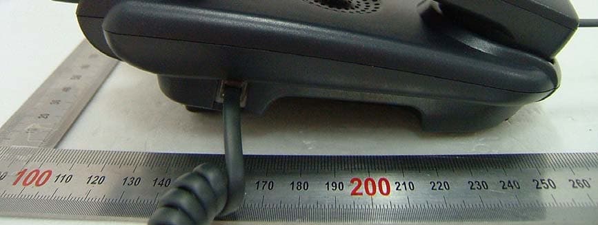
Click to zoom
Application Details
- Equipment Class
- PCB - PCS Licensed Transmitter
- Date of Grant
- Mar 24, 2008
- Application Purpose
- Original Equipment
- Date of Application
- Mar 24, 2008
- Equipment Note
- Quad Band GSM Fixed Wireless Phone
- Frequency Range
- 1850.20000000 - 1909.80000000
- Company
- Questlabs Corp.
- Country
- South Korea
Documents & Files
Document Text
Text extracted from the exhibit documents filed with the FCC. Open a document above to read the original.
Users Manual
GSM QUAD BAND FIXED WIRELESS PHONE USER MANUAL MODEL: SGP-6000 Rev 1.0 © QuestLabs Limited CONTENTS PAGE 1 Safety Instruction 4 2 Instruction 5 2.1 Front View of the phone 5 2.2 LCD display 6 2.3 Installation Guide 6 3 Basic operations 9 3.1 Making calls 9 3.2 Redialling the last number dialled 9 3.3 Receiving calls 9 3.4 Call waiting 10 3.5 Call Conferencing 10 3.6 Making international calls 10 3.7 Entering & Editing text 10 4 Menu tree 12 4.1 Contacts 14 4.2 Messages 16 4.3 Call log 19 4.4 Utilities 21 4.5 Organizer 22 4.6 Settings 23 5 General information 31 5.1 Specifications 31 5.2 Additional safety information 31 5.3 Troubleshooting 33 6. Conformance Statements 33 Rev 1.0 © QuestLabs Limited - 3 - WELCOME TO YOUR SGP-6000 Main Features z QUAD BAND(GSM 850/900/1800/1900) FIXED WIRELESS PHONE z 2.5” 128X64 MONOCHROME LCD ▪ ANIMATED CHARACTER AND ICON ON MAIN LCD ▪ 4-LINE TEXT DISPLAY ▪ VIEWING AREA : 59.0(W)X28.0(H) z 16-POLY FM MIDI z MULTI-NUMBER PHONE BOOK : NAME, 4 NUMBERS, GROUP, SPEED DIAL Rev 1.0 © QuestLabs Limited - 4 - 1. Safety Instruction Here is important information for safe and efficient operation. Please read this information before using your SGP-6000. For optimal performance, install this indoors. When specially used in an outdoor area, it may not work in below 0°C or over 50°C. Install SGP-6000 on hard, flat surface for proper ventilation. Avoid using SGP-6000 in high temperature or near a source of fire or gas. Avoid storing SGP-6000 in cold areas. Do not expose SGP-6000 to moisture or dust. Do not use SGP-6000 in the hospital. Do not use harsh chemicals, cleaning solvents to clean SGP-6000. And wipe with a soft, clean, dry cloth to clean it. Do not knock, drop, and shake SGP-6000 to avoid breaking the case. Use only the supplied or approved replacements. Only authorized personnel should service SGP-6000 and its accessories. Do not use SGP-6000 with a car battery. Do not touch the antenna when SGP-6000 is being used. Do not use the unit with a damaged antenna. Have your antenna replaced by a qualified technician immediately. Use only the provided antennas. Do not use the provided antennas for any other purpose. Use only the provided adapter. Do not use the provided adapter for any other purpose If the unit fails to work for any reason, do not attempt to disassemble. Rev 1.0 © QuestLabs Limited - 5 - 2. Instruction Front View of SGP-6000 NUMBER KEY DESCRIPTION 1 [SMS ] key Moves to ‘Messages’ menu 2 [Soft 1] key Activates phone’s main menu 3 [OK] key Moves to main menu 4 [Soft 2] key Moves to ‘Contacts’ menu 5 [CAL] key Activates ‘Calculator’ function 6 [∧] key Change Ring volume, or scrolls up in the menu 7 [∨] key Change Ring volume, or scrolls down in the menu 8 [Speaker] key Activates ‘Speakerphone’ function 9 [Send] key Dials a phone number and answers a call 10 [End] key Ends or rejects the call 11 [*] key Scrolls left in the menu 12 [#] key Scrolls right in the menu Rev 1.0 © QuestLabs Limited - 6 - 2.2 LCD display Icons display on the screen to indicate what features you are using, signal strength and the phone status etc. ICON OPERATING CONDITION Antenna : indicates strength of the received signal. The more bars indicate the stronger signal. Call divert : indicates that all calls are diverted. Message: shows when a text message is received Voice mail: shows when a voice message is received Call In use: indicates that a voice call is in progress. Alarm : shows when alarm time is set. Battery: indicates Battery charge level 2.3 Installation guide 2.3.1. Check the components Check to make sure that you have all the parts shown below after opening the package. If any piece is missing or broken, please call SGP-6000 sales agent or customer service. 1. HANDSET 2. MAIN UNIT 3. ANTENNA 4. BRACKET 5. DC POWER ADAPTER 6. LI-ION BACKUP BATTERY 7. USER MANUAL Rev 1.0 © QuestLabs Limited - 7 - 2.3.2. Install SIM card 1. Disconnect the power supply. 2. Open the SIM card cover on the bottom side. 3. Insert a SIM card into the socket as shown in the picture. 4. Close the SIM card cover. NOTE : Make sure the SIM card is aligned properly with the directional arrow on the holder. 2.3.3. Start SGP-6000 with the SIM card. 1. Power on your phone 2. Enter a PIN code 3. After entering the correct PIN code, the phone is ready to be used. Note: You have 3 chances to enter a PIN code. If incorrect Pin codes are entered 3times, a SIM card will be locked. To unlock it, you must contact your service provider. 2.3.4. Install battery 1. Disconnect the power supply. 2. Open the battery cover on the bottom side of the phone. 3. Connect the Battery cable to phone. 4. Close the battery cover. NOTE : Do not use SGP-6000 battery pack else. Using any other batteries may result in fire or other damage to the unit. 2.3.5. Desktop installation Before you select a location to place it, you must read 1.Safety Instruction section of this manual. 1. Screw the phone antenna into the phone antenna connector Rev 1.0 © QuestLabs Limited - 8 - * Note : finger-tighten the antenna. 2. Connect the handset cable to the phone jack and the handset Plug the DC Adaptor cord into the power supply and an appropriate power outlet. 3. Check signal strength of the antenna icon and move the unit until you find the best signal possible. 2.3.6. Wall mounting 1. Drill two holes at the marked locations. 2. Tighten screws until the head is about 3~5mm from the wall. 3. Hang SGP-6000 on the screw using two holes in the back. Rev 1.0 © QuestLabs Limited - 9 - 3. Basic operations 3.1 Making calls You can make a call as follows. 1. Make sure your phone is turned on. 2. Pick up the handset or press [Speaker] key. your phone is now off-hook 3. Listen for dial tone. 4. Dial the phone number. NOTE : To erase the last digit entered, press [Soft 2] key To erase all, press [Soft 2 ] key and hold it 5. Press [Send] key or wait for the Auto time-out. 6. The call is connected and you may start conversation. 7. To End the call, replace the…
Text truncated - open the document above for the full version.
Cover Letter(s)
6 th Floor Uniquest Bldg.,271-2 Seohyeon- Dong, Sungnam-Shi, Gyeonggi-Do, Korea 463- 824 March 6, 2008 MET Laboratories Inc. 914 W. Patapsco Ave. Baltimore, MD 21230 LETTER OF AUTHORIZATION To whom it may concern: We, the undersigned, hereby authorize Harvey Sung of DIGITAL EMC Co., Ltd., to act on our behalf in all manners relating to application for equipment authorization for FCC ID: VP3SGP6000 including signing of all documents relating to these matters. Any and all acts carried out by Harvey Sung of DIGITAL EMC Co., Ltd., on our behalf shall have the same affect as acts of our own. This authorization is valid until further written notice from Questlabs Corp. Sincerely, Edy Park / senior manager
Cover Letter(s)
6 th Floor Uniquest Bldg.,271-2 Seohyeon- Dong, Sungnam-Shi, Gyeonggi-Do, Korea 463-824 March 6, 2008 MET Laboratories Inc. 914 W. Patapsco Ave. Baltimore, MD 21230 In re: Questlabs Corp. FCC ID: VP3SGP6000 Request for Confidentiality Gentlemen: In accordance with 0.457 and 0.459 of CFR 47, Questlabs Corp. hereby requests confidentiality of the Block diagram(Block Diagram_ VP3SGP6000.pdf), Schematics(Schematic_ VP3SGP6000.pdf), Parts list(Part List_ VP3SGP6000.pdf) and Operational description(Operational Description_ VP3SGP6000.pdf). These documents contain detailed system and equipment description and related information about the product which Questlabs Corp. considers to be proprietary, confidential, and a custom design and, otherwise, would not release to the general public. Since this design is a basis from which future technological products will evolve, Questlabs Corp. considers that this information would be of benefit to its competitors, and that the disclosure of the information in these documents would give competitors an unfair advantage in the market. Sincerely, Edy Park / senior manager
Cover Letter(s)
6 th Floor Uniquest Bldg.,271-2 Seohyeon- Dong, Sungnam-Shi, Gyeonggi-Do, Korea 463-824 March 6, 2008 MET Laboratories Inc. 914 W. Patapsco Ave. Baltimore, MD 21230 In re: Questlabs Corp. FCC ID: VP3SGP6000 Request for Short-Term Confidentiality To Whom It May Concern: In accordance with 0.457 and 0.459 of CFR 47, Questlabs Corp. requests short-term Confidentiality of following sections of this application for a period of 45 days after grant is issued. Test setup photos(Test Photo_ VP3SGP6000.pdf) External photos(Ext Photo_ VP3SGP6000.pdf) Internal photos(Int Photo_ VP3SGP6000.pdf) User’s manual(User Manual_ VP3SGP6000.pdf) These documents contain detailed system and equipment descriptions and related information about the product, which Questlabs Corp. considers to be proprietary, confidential, and a custom design and otherwise, would not release to the general public. Since this design is a basis from which future technological products will evolve, Questlabs Corp. feels that this information would be of benefit to its competitors, and that the disclosure of the information in these documents would give our competitors an unfair advantage in the market. Sincerely, Edy Park / senior manager
External Photos
FCCID: VP3SGP6000 Copyright Ⓒ 2008, DIGITAL EMC Co., Ltd. View 1 FCCID: VP3SGP6000 Copyright Ⓒ 2008, DIGITAL EMC Co., Ltd. View 2 FCCID: VP3SGP6000 Copyright Ⓒ 2008, DIGITAL EMC Co., Ltd. View 3 FCCID: VP3SGP6000 Copyright Ⓒ 2008, DIGITAL EMC Co., Ltd. View4
ID Label/Location Info
FCC ID: VP3SGP6000 Copyright Ⓒ 2008, DIGITAL EMC Co., Ltd. FCC ID SAMPLE LABEL & LOCATION LABELLING REQUIREMENTS PER §2.925 The Label shown shall be permanently affixed at a conspicuous location on the device and be readily visible to the user at the time of purchase
Internal Photos
FCC ID: VP3SGP6000 Copyright Ⓒ 2008, DIGITAL EMC Co., Ltd. View 1 FCC ID: VP3SGP6000 Copyright Ⓒ 2008, DIGITAL EMC Co., Ltd. View 2 FCC ID: VP3SGP6000 Copyright Ⓒ 2008, DIGITAL EMC Co., Ltd. View 3 FCC ID: VP3SGP6000 Copyright Ⓒ 2008, DIGITAL EMC Co., Ltd. View 4 FCC ID: VP3SGP6000 Copyright Ⓒ 2008, DIGITAL EMC Co., Ltd. View 5 FCC ID: VP3SGP6000 Copyright Ⓒ 2008, DIGITAL EMC Co., Ltd. View 6
Parts List/Tune Up Info
CAM350 PRO V 7.0 : Tue Jan 22 17:48:36 2008 - (Untitled) : valu e1.gbr CAM350 PRO V 7.0 : Tue Jan 22 17:48:36 2008 - (Untitled) : valu e2.gbr CAM350 PRO V 7.0 : Tue Jan 15 14:02:54 2008 - (Untitled) : assy 1.gbr CAM350 PRO V 7.0 : Tue Jan 15 14:02:55 2008 - (Untitled) : assy 2.gbr
Parts List/Tune Up Info
Applicant: Questlabs Corp. FCC ID: VP3SGP6000 TUNE-UP PROCEDURE There are no user accessible adjustments or tuning in this GSM phone. All necessary adjustments and tuning are performed during manufacture of the product. Any adjustments or tuning after service or repair are done as part of that process as special equipment is required to perform such adjustments.
RF Exposure Info
MJ TELCOM SPECIFICATION Engineering Div. This product specification contains information proprietary to Mj telcom and should not be used without prior written permission. Sheet No.Rev No. PRODUCT SPECIFICATION MJ TELCOM A4(210X297) WLL Quad Band Antenna MQD-8899-DG 0OF 13 TITLE : WLL Quad Band BASE ANTENNA PART NUMBER : MQD-8899-DG GSM850: 824~894MHz / EGSM: 880~960MHz DCS :1710~1880MHz /PCS: 1850~1990MHz WRITTEN BY : CHECKED BY :APPROVED BY :DATE : Y.S. LEE REV NO. REVISION RECORDECNBYDATE 0PROPOSED MQD-8899-DG S.H.kim Y.W. LEE 2007.OCT.15 Y.S. LEE 2007.OCT.15. 1 MJ TELCOM SPECIFICATION Engineering Div. This product specification contains information proprietary to Mj telcom and should not be used without prior written permission. Sheet No.Rev No. PRODUCT SPECIFICATION MJ TELCOM A4(210X297) WLL Quad Band Antenna MQD-8899-DG 0OF 13 CONTENTS 1.DESCRIPTION 2. ELECTRICAL SPECIFICATIONS 3 MECHANICAL SPECIFICATIONS 4. V.S.W.R CHARACTERISTICS 5. ANTENNA DRAWING 6. ELECTRICAL TEST PROCEDURE 7. MECHANICAL TEST PROCEDURE 8. ENVIRONMENTAL TEST PROCEDURE 9. TEST FACILITIES 2 MJ TELCOM SPECIFICATION Engineering Div. This product specification contains information proprietary to Mj telcom and should not be used without prior written permission. Sheet No.Rev No. PRODUCT SPECIFICATION MJ TELCOM A4(210X297) WLL Quad Band Antenna MQD-8899-DG 0OF 13 1. DESCRIPTION 1.1 Scope A sleeve dipole antenna, consisting of copper cylinder and a thin radiator which is a inner conductor of a coaxial line, is a half wave dipole antenna used for a portable and base station unit for wireless communication. 1.2 Part Number MJ Telcom Antenna Part No. : MQD-8899-DG 1.3 Units and Definitions V.S.W.R : Voltage Standing Wave Ratio dBi : Antenna gain in dB relative to a isotropic antenna g : Acceleration of gravity (about 9.8 m/sec²) RH : Relative Humidity 1.4 Conditions Unless otherwise stated all temperature tolerance are ±3°Cand all RH tolerance are ±5 percentage units. Unless otherwise stated all values are valid at ±20°Cand 50% RH. 3 MJ TELCOM SPECIFICATION Engineering Div. This product specification contains information proprietary to Mj telcom and should not be used without prior written permission. Sheet No.Rev No. PRODUCT SPECIFICATION MJ TELCOM A4(210X297) WLL Quad Band Antenna MQD-8899-DG 0OF 13 2. ELECTRICAL SPECIFICATIONS 2-1 Frequency range : GSM850:824~894 MHz EGSM:880~960MHz DCS :1710~1880MHz PCS :1850~1990MHz 2-2 V.S.W.R : Less than 3.0:1 2-3 Gain (dBi) 824~894 MHz :1.68 ±0.5 (max) 880~960 MHz : 1.24 ±0.5 (max) 1710~1880 MHz : 0.5 ±0.5 (max) 1850~1990 MHz :0.72 ±0.5 (max) 2-4 Radiation pattern : Omni-directional 2-5 Polarization : VERTICAL 2-6 Power input(Watts) : 5(Max) 2-7 Antenna Type : Sleeve half Wave length dual dipole 2-8 Impedance : 50 ΩNominal 3.MECHANICAL SPECIFICATIONS 3-1 Overall Length of Ant.: 210.0 ±2.0 mm 3-2 Weight : 34 g 3-3 Connector Type : TNC-Male(Nickel plate) 3-4 Temperature : -30°C~+70°C 3-5 Cover material : Urethane x DARK GRAY 3-6 joint color : NYLON x DARK GRAY 3-7 Joint pin : BsBM x Nickel plate 3-8 RF Cable :RG 316S Brown color 4 MJ TELCOM SPECIFICATION Engineering Div. This product specification contains information proprietary to Mj telcom and should not be used without prior written permission. Sheet No.Rev No. PRODUCT SPECIFICATION MJ TELCOM A4(210X297) WLL Quad Band Antenna MQD-8899-DG 0OF 13 4.V.S.W.R Characteristics BASE set matching circuit ANT Coaxial cable to network analyzer 0Ω OPEN GND FEED POINT OPEN 5 MJ TELCOM SPECIFICATION Engineering Div. This product specification contains information proprietary to Mj telcom and should not be used without prior written permission. Sheet No.Rev No. PRODUCT SPECIFICATION MJ TELCOM A4(210X297) WLL Quad Band Antenna MQD-8899-DG 0OF 13 6. ANTENNA DRAWING NOTE: 1.Ant. Color :Dark gray 2.Connector finish:Nickel plate 3.All dimensions are in mm NO DESCRIPTION MATERIAL 1 2 3 4 5 COVER URETHANE JOINT “B” Nylon 66 JOINT “A” Nylon 66 JOINT PIN BsBm NixPLATE TNC-MALE BsBm NIxPLATE 6 MJ TELCOM SPECIFICATION Engineering Div. This product specification contains information proprietary to Mj telcom and should not be used without prior written permission. Sheet No.Rev No. PRODUCT SPECIFICATION MJ TELCOM A4(210X297) WLL Quad Band Antenna MQD-8899-DG 0OF 13 6. Electrical test procedure ITEMSpecificationsMeasuring method Frequency Range 824~894MHz, 880~960 MHz 880 ~960MHz 1850~1990 MHz Impedance Nominal value 50 Ω V.S.W.R Less than 3.0 : 1 A 50 ohms coaxial cable is connected to the TNC-FEMALEconnector. In the other end the coaxial cable is connected to a network analyzer The analyzer calibrated so that the reference plane is at the end the coaxial cable connected to the antenna. PRINT Network Analyzer HP-8753ES ≒ 6 0 m m F E D I N G L I N E WLL BASE ANT. 7 MJ TELCOM SPECIFICATION Engineering Div. This product specification contains information proprietary to Mj telcom and should not be used without prior written permission. Sheet No.Rev No. PRODUCT SPECIFICATION MJ TELCOM A4(210X297) WLL Quad Band Antenna MQD-8899-DG 0OF 13 7. Mechanical test procedure ITEMSpecificationsDemand Appearance 222.4 ±1 mm Tensile Load Force 3Kgf Refer to 6. DRAWING Without mechanical damage, electrical performance according to 2.(VSWR) after test The antenna is assembled to the test equipment according to figure. The specified force is applied during 30 sec to the top of the sleeve parallel to the antenna axis. ITEMSpecificationsDemand Drop Drop height : 30intch No. of drop : 18 times Set weight : 500 Kg No visual change and the fitting and mold shall be unchanged mechanically and satisfy the electrical data after test The antenna is dropped downwards onto a steel surface steel plate. WLL SET Antenna 30 INTCH F.L ±0.0m 7-1. Tensile Load 7-2. Drop 8 MJ TELCOM SPECIFICATION Engineering Div. This product specification contains information proprietary to Mj telcom and should not be used without prior written permission. Sheet No.Rev No. PRODUCT SPECIFICATION MJ TELCOM A4(210X2…
Text truncated - open the document above for the full version.
RF Exposure Info
G Copyright ̺ c 2008, DIGITAL EMC Co., Ltd. DIPOLE CALIBRATION G Copyright ̺ c 2008, DIGITAL EMC Co., Ltd. 1. 835 Dipole Calibration G Copyright ̺ c 2008, DIGITAL EMC Co., Ltd. 2. 1900 Dipole Calibration
RF Exposure Info
G G Copyright ̺ c 2008, DIGITAL EMC Co., Ltd. PROBE CALIBRATION
RF Exposure Info
DEMC#DR50110803L Copyright ○ c 2008, DIGITAL EMC Co., Ltd. Page 1 of 22 683-3, Yubang-Dong, Yongin-Si, Kyunggi-Do, Korea. 449-080 Tel: +82-31-321-2664 Fax: +82-31-321-1664 http://www.digitalemc.com SAR TEST REPORT Dates of Tests: February 28~29, 2008 Test Report S/N:DR50110803L Test Site : DIGITAL EMC CO., LTD. FCC ID APPLICANT FCC Classification: Licensed Non-Broadcast Station Transmitter(TNB) EUT Type: GSM Quad Band Fixed Wirelss Phone Model Name SGP-6000 Test Device Serial No.: Identical prototype TX Frequency Range: 824.20 ~848.80 MHz (GSM850) / 1850.20 ~ 1909.80 MHz (PCS1900) RX Frequency Range: 869.2 ~893.8 MHz (GSM850) / 1930.2 ~ 1989.8 MHz (PCS1900) Max. RF Output Power: 2.286W ERP GSM850 0.935W EIRP PCS1900 Max. SAR Measurement: 0.775 mW/g GSM850 Body SAR 0.079 mW/g PCS1900 Body SAR Application Type: Certification Rule Part(s): §2.1093; FCC/OET Bulletin Supplement C[July 2001] Data of issue: March 14, 2008 Tested by : Reviewed by : Sun-Kyu Ryu (Engineer) Harvey Sung (Chief Engineering Director) This wireless portable device has been shown to be capable of compliance for localized specific absorption rate (SAR) for uncontrolled environment/general population exposure limits specified in ANSI/IEEE Std. C95.1-1992 and had been tested in accordance with the measurement procedures specified in FCC/OET Bulletin 65 Supplement C (2001) and IEEE Std. 1528-2003. I attest to the accuracy of data. All measurements reported herein were performed by me or were made under my supervision and are correct to the best of my knowledge and belief. I assume full responsibility for the completeness of these measurements and vouch for the qualifications of all persons taking them. VP3SGP6000 Questlabs Corp. DEMC#DR50110803L Copyright ○ c 2008, DIGITAL EMC Co., Ltd. Page 2 of 22 1. INTRODUCTION ...................................................................................................... 3 SAR DEFINITION .................................................................................................... 3 2. SAR MEASUREMENT SETUP......................................................................................... 4 Robotic System.......................................................................................................... 4 System Hardware ....................................................................................................... 4 System Electronics...................................................................................................... 4 3. DASY4 E-FIELD PROBE SYSTEM................................................................................... 5 Probe Measurement System......................................................................................... 5 Probe Specifications .................................................................................................... 5 4. Probe Calibration Process............................................................................................ 6 Dosimetric Assessment Procedure.................................................................................. 6 Free Space Assessment ............................................................................................... 6 Temperature Assessment ............................................................................................ 6 5. PHANTOM & EQUIVALENT TISSUES.............................................................................. 7 SAM Phantom ........................................................................................................... 7 Brain & Muscle Simulating Mixture Characterization ....................................................... 7 Device Holder for Transmitters..................................................................................... 7 6. TEST SYSTEM SPECIFICATIONS.................................................................................. 8 Automated Test System Specifications.......................................................................... 8 7. DOSIMETRIC ASSESSMENT & PHANTOM SPECS ........................................................... 9 Measurement Procedure............................................................................................. 9 Specific Anthropomorphic Mannequin (SAM) Specifications.............................................. 9 8. DEFINITION OF REFERENCE POINTS .......................................................................... 10 EAR Reference Point................................................................................................... 10 Handset Reference Points............................................................................................ 10 9. TEST CONFIGURATION POSITIONS ............................................................................. 11 Positioning for Cheek/Touch ........................................................................................ 11 Positioning for Ear /15° Tilt ......................................................................................... 12 Body Holster /Belt Clip Configurations .......................................................................... 13 10. ICNIRP GUIDELINES RF EXPOSURE LIMITS.................................................................. 14 Uncontrolled Environment ........................................................................................... 14 Controlled Environment............................................................................................... 14 11. MEASUREMENT UNCERTAINTIES............................................................................... 15 SAR Measurement Uncertainties .................................................................................. 15 12. SYSTEM VERIFICATION........................................................................................... 16 Tissue Verification................................................................................................…
Text truncated - open the document above for the full version.
RF Exposure Info
DEMC#DR50110803L Copyright Ⓒ 2008, DIGITAL EMC Co., Ltd. SAR TEST SET UP PHOTO DEMC#DR50110803L Copyright Ⓒ 2008, DIGITAL EMC Co., Ltd. View 1 DEMC#DR50110803L Copyright Ⓒ 2008, DIGITAL EMC Co., Ltd. View 2(Body)
RF Exposure Info
DIGITAL EMC CO., LTD DUT: Dipole 835 MHz; Type: D835V2; Serial: D835V2 - SN:464 Communication System: CW; Frequency: 835 MHz;Duty Cycle: 1:1 Medium parameters used: f = 835 MHz; σ = 0.915 mho/m; ε r = 41.2; ρ = 1000 kg/m 3 Phantom section: Flat Section DASY4 Configuration: Probe: ET3DV6 - SN1702; ConvF(6.34, 6.34, 6.34); Calibrated: 2007-03-20; Electronics: DAE3 Sn520 Phantom: SAM with 835MHz; Type: SAM; Serial: TP-1223 Measurement SW: DASY4, V4.7 Build 55; Postprocessing SW: SEMCAD, V1.8 Build 176 Test Date: 2008-02-28; Ambient Temp: 20.7; Tissue Temp: 20.5 Dipole Validation Area Scan (51x101x1): Measurement grid: dx=15mm, dy=15mm Zoom Scan (7x7x7)/Cube 0: Measurement grid: dx=5mm, dy=5mm, dz=5mm Power Drift = -0.009 dB Peak SAR (extrapolated) = 3.62 W/kg SAR(1 g) = 2.41 mW/g; SAR(10 g) = 1.57 mW/g 0 dB = 2.60mW/g DIGITAL EMC CO., LTD DUT: Dipole 1900 MHz; Type: D1900V2; Serial: D1900V2 - SN:5d029 Communication System: CW; Frequency: 1900 MHz;Duty Cycle: 1:1 Medium parameters used: f = 1900 MHz; σ = 1.41 mho/m; ε r = 40.2; ρ = 1000 kg/m 3 Phantom section: Flat Section DASY4 Configuration: Probe: ET3DV6 - SN1702; ConvF(5.27, 5.27, 5.27); Calibrated: 2007-03-20; Electronics: DAE3 Sn520 Phantom: SAM 1800/1900 MHz; Type: SAM; Serial: TP-1224 Measurement SW: DASY4, V4.7 Build 55; Postprocessing SW: SEMCAD, V1.8 Build 176 Test Date: 2008-02-29; Ambient Temp: 20.4; Tissue Temp: 20.3 Dipole Validation Area Scan (51x71x1): Measurement grid: dx=15mm, dy=15mm Zoom Scan (7x7x7)/Cube 0: Measurement grid: dx=5mm, dy=5mm, dz=5mm Power Drift = -0.020 dB Peak SAR (extrapolated) = 18.2 W/kg SAR(1 g) = 10.3 mW/g; SAR(10 g) = 5.35 mW/g 0 dB = 11.7mW/g DIGITAL EMC CO., LTD DUT: SGP6000; Type: WLL Communication System: GSM 850; Frequency: 824.2 MHz;Duty Cycle: 1:8.3 Medium parameters used: f = 824.2 MHz; σ = 0.984 mho/m; ε r = 53.8; ρ = 1000 kg/m 3 Phantom section: Flat Section DASY4 Configuration: Probe: ET3DV6 - SN1702; ConvF(6.22, 6.22, 6.22); Calibrated: 2007-03-20; Electronics: DAE3 Sn520 Phantom: SAM with 835MHz; Type: SAM; Serial: TP-1223 Measurement SW: DASY4, V4.7 Build 55; Postprocessing SW: SEMCAD, V1.8 Build 176 Test Date: 2008-02-28; Ambient Temp: 20.7; Tissue Temp: 20.5 2.5cm from Body, GSM Ch.128, Ant Fixed, Charger Mode Area Scan (51x151x1): Measurement grid: dx=15mm, dy=15mm Zoom Scan (5x5x7)/Cube 0: Measurement grid: dx=8mm, dy=8mm, dz=5mm Power Drift = -0.044 dB Peak SAR (extrapolated) = 1.04 W/kg SAR(1 g) = 0.775 mW/g; SAR(10 g) = 0.549 mW/g 0 dB = 0.826mW/g DIGITAL EMC CO., LTD DUT: SGP6000; Type: WLL Communication System: GSM 850; Frequency: 836.6 MHz;Duty Cycle: 1:8.3 Medium parameters used: f = 836.6 MHz; σ = 0.997 mho/m; ε r = 53.9; ρ = 1000 kg/m 3 Phantom section: Flat Section DASY4 Configuration: Probe: ET3DV6 - SN1702; ConvF(6.22, 6.22, 6.22); Calibrated: 2007-03-20; Electronics: DAE3 Sn520 Phantom: SAM with 835MHz; Type: SAM; Serial: TP-1223 Measurement SW: DASY4, V4.7 Build 55; Postprocessing SW: SEMCAD, V1.8 Build 176 Test Date: 2008-02-28; Ambient Temp: 20.7; Tissue Temp: 20.5 2.5cm from Body, GSM Ch.190, Ant Fixed, Charger Mode Area Scan (51x151x1): Measurement grid: dx=15mm, dy=15mm Zoom Scan (5x5x7)/Cube 0: Measurement grid: dx=8mm, dy=8mm, dz=5mm Power Drift = -0.047 dB Peak SAR (extrapolated) = 0.783 W/kg SAR(1 g) = 0.614 mW/g; SAR(10 g) = 0.438 mW/g 0 dB = 0.658mW/g DIGITAL EMC CO., LTD DUT: SGP6000; Type: WLL Communication System: GSM 850; Frequency: 848.8 MHz;Duty Cycle: 1:8.3 Medium parameters used: f = 848.8 MHz; σ = 1 mho/m; ε r = 53.7; ρ = 1000 kg/m 3 Phantom section: Flat Section DASY4 Configuration: Probe: ET3DV6 - SN1702; ConvF(6.22, 6.22, 6.22); Calibrated: 2007-03-20; Electronics: DAE3 Sn520 Phantom: SAM with 835MHz; Type: SAM; Serial: TP-1223 Measurement SW: DASY4, V4.7 Build 55; Postprocessing SW: SEMCAD, V1.8 Build 176 Test Date: 2008-02-28; Ambient Temp: 20.7; Tissue Temp: 20.5 2.5cm from Body, GSM Ch.251, Ant Fixed, Charger Mode Area Scan (51x151x1): Measurement grid: dx=15mm, dy=15mm Zoom Scan (5x5x7)/Cube 0: Measurement grid: dx=8mm, dy=8mm, dz=5mm Power Drift = 0.044 dB Peak SAR (extrapolated) = 0.756 W/kg SAR(1 g) = 0.566 mW/g; SAR(10 g) = 0.397 mW/g 0 dB = 0.605mW/g DIGITAL EMC CO., LTD DUT: SGP6000; Type: WLL Communication System: PCS1900; Frequency: 1850.2 MHz;Duty Cycle: 1:8.3 Medium parameters used (extrapolated): f = 1850.2 MHz; σ = 1.45 mho/m; ε r = 55.2; ρ = 1000 kg/m 3 Phantom section: Flat Section DASY4 Configuration: Probe: ET3DV6 - SN1702; ConvF(4.93, 4.93, 4.93); Calibrated: 2007-03-20; Electronics: DAE3 Sn520 Phantom: SAM 1800/1900 MHz; Type: SAM; Serial: TP-1224 Measurement SW: DASY4, V4.7 Build 55; Postprocessing SW: SEMCAD, V1.8 Build 176 Test Date: 2008-02-29; Ambient Temp: 20.4; Tissue Temp: 20.3 2.5cm from Body, PCS Ch.512, Ant Fixed, Charger Mode Area Scan (51x131x1): Measurement grid: dx=15mm, dy=15mm Zoom Scan (5x5x7)/Cube 0: Measurement grid: dx=8mm, dy=8mm, dz=5mm Power Drift = 0.091 dB Peak SAR (extrapolated) = 0.119 W/kg SAR(1 g) = 0.079 mW/g; SAR(10 g) = 0.051 mW/g 0 dB = 0.084mW/g DIGITAL EMC CO., LTD DUT: SGP6000; Type: WLL Communication System: PCS1900; Frequency: 1850.2 MHz;Duty Cycle: 1:8.3 Medium parameters used (extrapolated): f = 1850.2 MHz; σ = 1.45 mho/m; ε r = 55.2; ρ = 1000 kg/m 3 Phantom section: Flat Section DASY4 Configuration: Probe: ET3DV6 - SN1702; ConvF(4.93, 4.93, 4.93); Calibrated: 2007-03-20; Electronics: DAE3 Sn520 Phantom: SAM 1800/1900 MHz; Type: SAM; Serial: TP-1224 Measurement SW: DASY4, V4.7 Build 55; Postprocessing SW: SEMCAD, V1.8 Build 176 Test Date: 2008-02-29; Ambient Temp: 20.4; Tissue Temp: 20.3 2.5cm from Body, PCS Ch.512, Ant Fixed, Charger Mode Area Scan (51x131x1): Measurement grid: dx=15mm, dy=15mm Zoom Scan (5x5x7)/Cube 1: Measurement grid: dx=8mm, dy=8mm, dz=5mm Power Drift = 0.091 dB Peak SAR (extrapolated) = 0.087 W/kg SAR(1 g) = 0.060 mW/g; SAR(10 g) = 0.039 mW/g 0 dB = 0.064mW/g DIGITAL EMC CO., LTD DUT: SGP6000; Type: WLL Communication System: PCS1900; Frequency: 1880 MHz;Duty …
Text truncated - open the document above for the full version.
Test Report
DEMC#DR50110803Q Copyright ○ c 2008, DIGITAL EMC Co., Ltd. Page 1 of 48 683-3, Yubang-Dong, Yongin-Si, Kyunggi-Do, Korea. 449-080 Tel: +82-31-321-2664 Fax: +82-31-321-1664 http://www.digitalemc.com CERTIFICATE OF COMPLIANCE FCC Part 22 & 24 Certification Dates of Tests: March 7 ~ 15, 2008 Test Report S/N:DR50110803Q Test Site : DIGITAL EMC CO., LTD. FCC ID. APPLICANT Classification : Licensed Non-Broadcast Station Transmitter(TNB) FCC Rule Part(s) : §22(H), §24(E), §2 EUT Type : GSM Quad Band Fixed Wirelss Phone Model name : SGP-6000 Serial number : Identical prototype TX Frequency Range : 824.2 ~ 848.8 MHz (GSM850) / 1850.2 ~ 1909.8 MHz (PCS1900) RX Frequency Range : 869.2 ~ 893.8 MHz (GSM850) / 1930.2 ~ 1989.8 MHz (PCS1900) Max. RF Output Power : 2.286W ERP GSM850 : 0.935W EIRP PCS1900 Max. SAR Measurement : 0.775mW/g GSM850 GSM Body SAR : 0.079mW/g PCS1900 GSM Body SAR Date of Issue : March 17, 2008 VP3SGP…
Text truncated - open the document above for the full version.
Contact Information
Applicant
Jay Kang
Non-Technical Contact
Digital EMC Co. Ltd.Harvey Sung
[email protected]+82-31-321-2664
Test Firm
DT&C Co.,Changho Lee
Technical Specifications
| # | Rule Parts | Frequency Range | Power Output | Emission | Tolerance |
|---|---|---|---|---|---|
| 2 | 24E | 1.85 GHz - 1.91 GHz | 935.00 mW | 235KGXW | 2.5 ppm |