VPWVTGTRS1REMOTE SHUTTER CONTROLLER
StormEasy Shutters Inc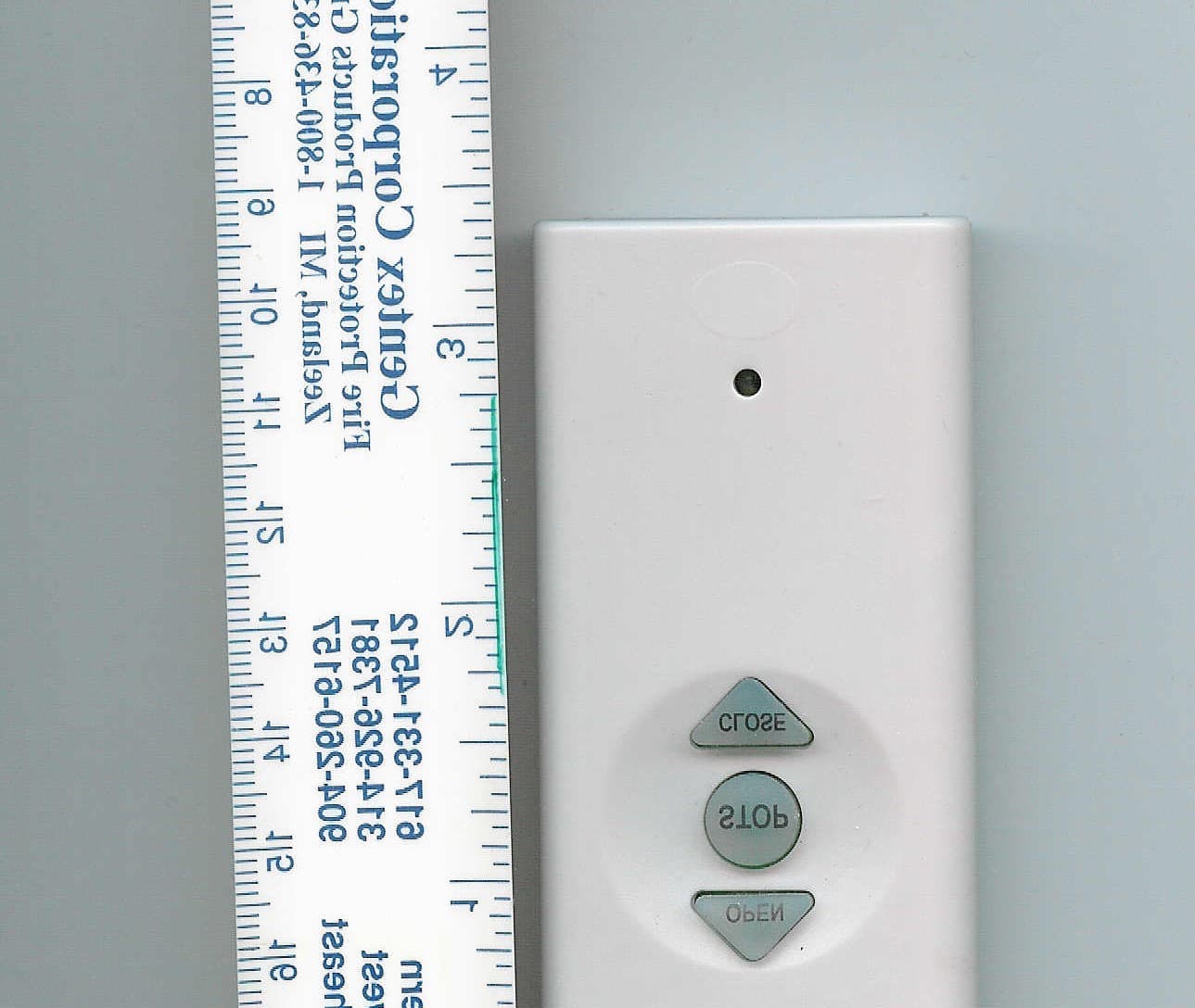
Click to zoom
Application Details
- Equipment Class
- DSC - Part 15 Security/Remote Control Transmitter
- Date of Grant
- Apr 06, 2008
- Application Purpose
- Original Equipment
- Date of Application
- Apr 06, 2008
- Equipment Note
- REMOTE SHUTTER CONTROLLER
- Frequency Range
- 433.50000000 - 434.50000000
- Company
- StormEasy Shutters Inc
- Country
- United States
Documents & Files
Document Text
Text extracted from the exhibit documents filed with the FCC. Open a document above to read the original.
Users Manual
FCC registered radio transmitter device. This device is FCC compliant, and registered, with the agency as: FCC ID: VPWVTGTRG1 ________________________________________________ Important: "This device complies with Part 15 of the FCC Rules. Operation is subject to the following two conditions: (1) this device may not cause harmful interference, and (2) this device must accept any interference received, including interference that may cause undesired operation." "Any changes or modifications not expressly approved by the party responsible for compliance could void the user's authority to operate the equipment." ______________________________________________ Read fully, before proceeding! To program intended receiver(s) Once the intended receiver(s) are wired (and powered "ON") according to packaged instructions, insert a small pin like object (or unfolded paper clip) into the hole, on the back of the transmitter, while the intended receiver(s), and only the intended receiver(s), are powered "ON" (within the transmitting distance, of the device). Caution: Any powered "ON" receiver, within transmitting distance, will be trained to that particular code, so extra care is necessary, to train only the intended receivers to that particular code, or channel! Multiple receivers can be trained to the same code (intentionally, or unintentionally). Care must be exerted to assure that only the proper receivers are trained to an intended channel! Any receiver within the transmitting range of the device, not intended to receive the learning code, needs to be "powered off", while the learning process is on going! After all programming is completed, as desired, each unit can again be powered on, and used accordingly, with the transmitter. The transmitter is designed to work with a maximum of 5 receivers (and has a button for "all"). If additional transmitters are needed, after acquiring them, they also can be trained to individual motors, and/or intended grouping of motors. Keep all transmitters dry, and replace battery, as needed! _______________________________________________________________ Wiring the receivers To wire the receiver boards, be certain that intended wires are not powered ON, until after the process is completed! Each board contains a terminal strip with seven terminals, at the bottom, and three low voltage terminals, at the top. The bottom terminals receive the following wires left, to right.. (1 through 7, holding the board upright, with 7 terminals, at the bottom). 1 = Ground wire, from house panel 2 = 110 volt A/C from house panel 3 = Neutral wire, from house panel 4 = Motor direction 1 (red from motor) 5 = Motor direction 2 (black from motor) 6 = White neutral wire, from motor 7 = Green (ground) wire from motor Be absolutely certain wiring is correct, before powering board “ON”! Note if the motor runs in the reverse direction as wanted, reverse the number 4 & 5 wires, after turning “off” the power. Low Voltage back-up terminals 3 each (at top) These wires do not connect to anything, except a momentary contact switch, (or switches). Left to right..... 1 = up 2 = Down 3 = Common to both Important/ Locate receiver in a dry place, where weather can not , in any way, get inside of the receiver! If service is required, always disconnect 110 volt A/C power, before opening receiver(s)!
Test Report
Test Report Number 07F299BPage A3 of A7 FCC ID: VPWVTGTRS1Test Report Number 07F299BPage A4 of A7 FCC ID: VPWVTGTRS1Test Report Number 07F299BPage A5 of A7 FCC ID: VPWVTGTRS1Test Report Number 07F299BPage A6 of A7 FCC ID: VPWVTGTRS1Test Report Number 07F299BPage A7 of A7
Contact Information
Applicant
Dane Horstead(President)
Test Firm
TUV SUD America Inc.William Elliott
Technical Specifications
| # | Rule Parts | Frequency Range | Power Output |
|---|---|---|---|
| 1 | 15.231 | 433.5 MHz - 434.5 MHz | - |
Other Applications from StormEasy Shutters Inc
VPWVTGTRG1
Nov 12, 2007REMOTE SHUTTER CONTROLLER
Equipment Class
DSC - Part 15 Security/Remote Control Transmitter