Click to zoom
Application Details
- Equipment Class
- DSS - Part 15 Spread Spectrum Transmitter
- Date of Grant
- Mar 08, 2011
- Application Purpose
- Original Equipment
- Date of Application
- Mar 07, 2011
- Equipment Note
- Bluetoooth Headset
- Frequency Range
- 2402.00000000 - 2480.00000000
- Company
- Armour Automotive Ltd
- Country
- United Kingdom
Documents & Files
Select a file to view
Users Manual
Cover Letter(s)
External Photos
ID Label/Location Info
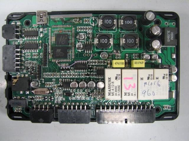
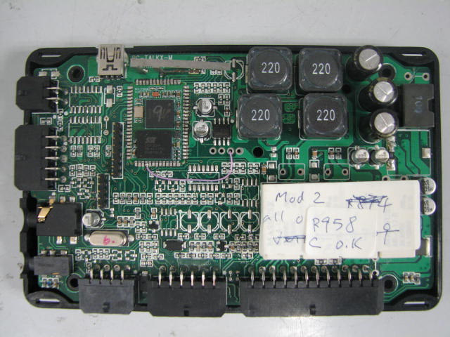
Internal Photos
Test Report
Test Setup Photos
Contact Information
Applicant
dON Tolson(MR.)
Test Firm
Hong Kong Productivity CouncilIr Angel Wong Yuen-yee
Technical Specifications
| # | Rule Parts | Frequency Range | Power Output |
|---|---|---|---|
| 1 | 15C | 2.40 GHz - 2.48 GHz | 3.00 mW |
Other Applications from Armour Automotive Ltd
VUHIOTLK2
Mar 07, 2011Bluetooth Headset
Equipment Class
DSS - Part 15 Spread Spectrum Transmitter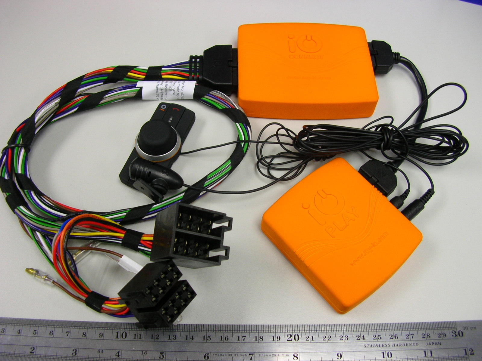
VUHIOPLAY
Dec 16, 2007Bluetooth Car Kit
Equipment Class
DSS - Part 15 Spread Spectrum Transmitter