VVX-LM959BLUETOOTH VIBRATING BRACELET
LM Technologies Ltd.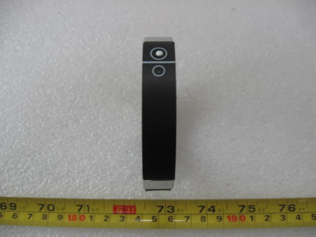
Click to zoom
Application Details
- Equipment Class
- DSS - Part 15 Spread Spectrum Transmitter
- Date of Grant
- Mar 27, 2008
- Application Purpose
- Original Equipment
- Date of Application
- Mar 27, 2008
- Equipment Note
- BLUETOOTH VIBRATING BRACELET
- Frequency Range
- 2402.00000000 - 2480.00000000
- Company
- LM Technologies Ltd.
- Country
- United Kingdom
Documents & Files
Document Text
Text extracted from the exhibit documents filed with the FCC. Open a document above to read the original.
Users Manual
)../6!4)6%4%#(./,/'902/$5#43 LM959 Bluetooth Vibrating Bracelet 1. Getting Started Welcome to the LM Technologies Bluetooth Bracelet. Please read this manual carefully before using this bracelet. • Important: Please charge the Bluetooth Bracelet for 6 hours before using it the first time. • It notifies you when your phone rings with a discreet vibrating sensation. • The Bluetooth Bracelet will also alert you when you mobile is more than 5 Meters away from you. 2 Charging the Bracelet 2.1 Plug the small adaptor into the bracelet and then turn on the AC mains at the wall. 2.2 Charging time Normally, the bracelet battery will be fully charged after about 2 hours. When the battery is full the bracelet will stop charge automatically. Then, hold the “power on/off” button for 2 seconds to turn on the bracelet. (Please refer to the picture for the button 2.3. Charging indicator When the bracelet is charged, red LED light on. Once the battery is full , then the LED will turn off automatically. 2.4 Standby Time When the battery is full the standby time is 100 hours. 2.5 Low Battery when the bracelet is on and the battery becomes low, the red LED will blink every 1 minute. At that time, please recharge the battery as per the above steps. 3 Turn on/off bracelet 3.1 Turn on the bracelet Press and hold “power on /off” button for 2 seconds until the green LED flashes quickly. 3.2 Turn off the bracelet Press and hold “power on /off” button for 4 seconds until the LED flashes quickly. 4.1 Pairing bracelet with phone This bracelet is to be used with Bluetooth enabled mobile phone. Setting up as below: • Keep bracelet and phone within 1 meter apart • Make sure the bracelet is turned off • Hold the “power on /off” button for 4 seconds until the green and blue LED flash alternatively. • Initiate Bluetooth function on your mobile phone, and then search for Bluetooth devices. If it is successful, the mobile phone will show the name of Bluetooth device “bracelet”. • Press “yes” to pair this bracelet with phone. • Input ID code of bracelet “0000”, Press “Yes”to complete pairing, then green LED will flash 5 times, so that bracelet is under stand-by mode and ready for Bluetooth communication .Press locate this bracelet within 10 meters (max. ) to phones. Notice: If pairing process can’t be completed within 2 minutes, the red LED will flash and the bracelet will turn off automatically. 5. Link bracelet with phone Once pairing is successful, the bracelet is in stand-by mode. 1. Press “power on / off” button and the bracelet will be connected to phone and press “Yes” on the phone to accept reconnect mode. 2. Operate phone manual to enable Bluetooth function and then going into program of paired device and select“bracelet ” 6. Using the Bracelet When a call is coming in the bracelet will vibrate and a red LED will light. Some brands of mobile phones will activate the vibrate feature of the Bracelt and a red LED will flash when a SMS is received The Bracelet will vibrate and a red LED flash when the distance is more than 10m between the mobile phone and bracelet. 7. To reset the Bracelet You may want to reset the bracelet to original setting. This also clears all current settings. 1. Assure the bracelet is OFF. 2. Constantly press “power on/off” button until LED blinks red and green colour. 3. Release the “power on/off” button. 4. Hold “power on/off” button 4 seconds. 5. Recharge power to the bracelet for a few seconds. 6. The bracelet will turn off and returns to the original setting mode. All of previous pairing data are cleared. 8 Warning 8.1 Bracelet • Please turn off the bracelet before putting it on your wrist. • Do not expose the bracelet to liquid, moisture or humidity as is not waterproof. • Do not use abrasive cleaning solvents to clean the bracelet. • Do not expose the bracelet under high or low temperatures. • Do not expose your bracelet to sharp objects as this will cause scratches and damage. • Do not stick anything on inside of the bracelet as this may damage internal components. • If you don’t use the bracelet for a long period, store it in a dry place and far away from extreme temperatures and dust. 8.2 Built-in battery • Do not attempt to replace the bracelet’s battery by yourself as it is built-in recharged battery and we strongly recommend you do not open the case of the battery. • Only use the supplied charger to charge the bracelet. • Do not use the charger outdoors or under humid environment. • Avoid charging the Bracelet in extremely high or low temperatures. 5. Technical specification: Bluetooth V1.2 Class2 standard (10M) Availability distance 5-10M Automatic battery power saving Safety attention, data encrypt 10 days active battery life 120-240V AC adapter with 5V DC Output One (1) Year International warranty Your LM Technologies bracelet is warranted by your supplier for a period of one (1) year from the original data of purchase under the terms and conditions of this warranty. This warranty covers materials and manufacturing defects. Your supplier will require proof of purchase before replacing the defective product. During the warranty period the bracelet movement, hands and dial are the only parts covered under this warranty. A covered component will be repaired or the bracelet will be replace free of repair charges, if it proves to be defective in material or workmanship under normal use. In case of replacement, LM Technologies cannot guarantee that you will receive the same model bracelet. If your model is not available, a bracelet of equal value and similar style will be provided. The warranty for the replacement bracelet ends one (1) year from the data the replacement bracelet is received. THIS WARRANTY DOES NOT COVER •Any defects in materials and workmanship of battery, case, crystal, strap or bracelet. •Damage resulting from improper handling, lack of care, accidents, or normal wear and tear. •Water damage unless marked water resistant This warranty is void if the bracelet has been…
Text truncated - open the document above for the full version.
Block Diagram
Antenna 2402-2480MHz Block Diagram OSC 48MHz Bluetooth Core Chip Flash Memory Power Supply LED Indicator
Cover Letter(s)
LM Technologies Ltd 66-68 Hagley Road, Birmingham B16 8PF, West Midlands, United Kingdom. (FCC ID:VVX-LM959) POWER OF ATTORNEY March 22, 2008 Federal Communications Commission Authorization and Evaluation Division 7435 Oakland Mills Road Columbia, MD 21046 To Whom It May Concern: We, the undersigned, hereby authorize SEM.Test Compliance Service Co., Ltd. Jandy So on our behalf, to apply to the Federal Communications Commission on our equipment. Any and all acts carried out by SEM.Test Compliance Service Co., Ltd. Jandy So on our behalf shall have the same effect as acts of our own. This is to advise that we are in full compliance with the Anti-Drug Abuse Act. We, LM Technologies Ltd, are not subject to a denial of federal benefits pursuant to Section 5301 of the Anti-Drug Act of 1988, 21 USC853a, and no party to the application is subject to a denial of federal benefits pursuant to that section. Sincerely, LM Technologies Ltd ------------------------------- (Michael Sims) (Director)
External Photos
LM TECHNOLOGIES LTD. MODEL: LM959 REPORT NO.: STR08038101I FCC PART 15.247 EXHIBIT 2 - EUT EXTERNAL PHOTOGRAPHS EUT View 1 EUT View 2
ID Label/Location Info
LM TECHNOLOGIES LTD. MODEL: LM959 REPORT NO.: STR08038101I FCC PART 15.247 EXHIBIT 1- PRODUCT LABELING Proposed FCC ID Label Format FCC ID: VVX-LM959 Specifications : Text is Black in color and justified. Labels are printed in indelible ink on permanent adhesive silk-screened onto the EUT or shall be affixed at a conspicuous location on the EUT. Proposed Label Location on EUT FCC ID Label Location
ID Label/Location Info
LM TECHNOLOGIES LTD. MODEL: LM959 REPORT NO.: STR08038101I FCC PART 15.247 EXHIBIT 1- PRODUCT LABELING Proposed FCC ID Label Format FCC ID: VVX-LM959 Specifications : Text is Black in color and justified. Labels are printed in indelible ink on permanent adhesive silk-screened onto the EUT or shall be affixed at a conspicuous location on the EUT. Proposed Label Location on EUT FCC ID Label Location
Internal Photos
LM TECHNOLOGIES LTD. MODEL: LM959 REPORT NO.: STR08038101I FCC PART 15.247 EXHIBIT 3 - EUT INTERNAL PHOTOGRAPHS EUT Housing and Board View Solder Board-Component View 1 LM TECHNOLOGIES LTD. MODEL: LM959 REPORT NO.: STR08038101I FCC PART 15.247 Solder Board-Component View 2
Operational Description
Circuit Description The IC U1 is a bluetooth chip that receiving the signal in 2.4GHz hopping frequency technology and decoding the signal, the crystal X1 generator the 48MHz clock to U1, and U4 is flash memory for U1, the U3 is power supply and convert.
Test Report
LM TECHNOLOGIES LTD. MODEL: LM959 REPORT NO.: STR08038101I PAGE 1 OF 26 FCC PART 15.247 FCC Part 15C Measurement and Test Report For Lm technologies Ltd. 66-68 Hagley Road Birmingham B16 8PF West Middle, United Kingdom. FCC ID: VVX-LM959 Report Concerns: Original Report Equipment Type: Bluetooth Vibrating Bracelet Model: LM959 Report No.: STR08038101I Test/Witness Engineer: Test Date: 2007-03-17 to 2007-03-25 Prepared By: Shenzhen SEM.Test Compliance Service Co., Ltd 3/F, Jinbao Commerce Building, Xin'an Fanshen Road, Bao'an District, Shenzhen, P.R.C.(518101) Approved & Authorized By: Jandy So / PSQ Manager Note: This test report is limited to the above client company and the product model only. It may not be duplicated without prior permitted by SEM.Test Compliance Service Co., Ltd . LM TECHNOLOGIES LTD. MODEL: LM959 REPORT NO.: STR08038101I PAGE 2 OF 26 FCC PART 15.247 TABLE OF CONTENTS 1. GENERAL INFORMATION ...................................................................................................................................3 1.1 PRODUCT DESCRIPTION FOR EQUIPMENT UNDER TEST (EUT)...............................................................................3 1.2 TEST STANDARDS..................................................................................................................................................3 1.3 RELATED SUBMITTAL(S)/GRANT(S) .......................................................................................................................3 1.4 TEST METHODOLOGY............................................................................................................................................4 1.5 TEST FACILITY.......................................................................................................................................................4 1.6 EUT EXERCISE SOFTWARE....................................................................................................................................4 1.7 ACCESSORIES EQUIPMENT LIST AND DETAILS.......................................................................................................4 1.8 EUT CABLE LIST AND DETAILS.............................................................................................................................4 2. SUMMARY OF TEST RESULTS ...........................................................................................................................5 3. §15.203 - ANTENNA REQUIREMENT..................................................................................................................6 3.1 STANDARD APPLICABLE........................................................................................................................................6 3.2 TEST RESULT.........................................................................................................................................................6 4. NUMBER OF HOPPING CHANNELS AND CHANNEL SPACING .................................................................7 4.1 STANDARD APPLICABLE........................................................................................................................................7 4.2 TEST EQUIPMENT LIST AND DETAILS.....................................................................................................................7 4.3 TEST PROCEDURE...................................................................................................................................................7 4.4 ENVIRONMENTAL CONDITIONS..............................................................................................................................7 4.5 SUMMARY OF TEST RESULTS/PLOTS......................................................................................................................8 5. DWELL TIME OF A HOPPING CHANNEL ......................................................................................................10 5.1 STANDARD APPLICABLE......................................................................................................................................10 5.2 TEST EQUIPMENT LIST AND DETAILS...................................................................................................................10 5.3 TEST PROCEDURE.................................................................................................................................................10 5.4 ENVIRONMENTAL CONDITIONS............................................................................................................................10 5.5 SUMMARY OF TEST RESULTS/PLOTS....................................................................................................................11 6. 20-DB BANDWIDTH ..............................................................................................................................................13 6.1 STANDARD APPLICABLE......................................................................................................................................13 6.2 TEST EQUIPMENT LIST AND DETAILS...................................................................................................................13 6.3 TEST PROCEDURE.................................................................................................................................................13 6.4 ENVIRONMENTAL CONDITIONS............................................................................................................................13 6.5 SUMMARY OF TEST RESULTS/PLOTS....................................................................................................................13 7. POWER OUTPUT...................................................................................................................................................16 7.1 STANDARD APPLICABLE........................................................................................…
Text truncated - open the document above for the full version.
Test Setup Photos
LM TECHNOLOGIES LTD. MODEL: LM959 REPORT NO.: STR08038101I FCC PART 15.247 EXHIBIT 4 - TEST SETUP PHOTOGRAPHS Radiation Emission Test Setup (30MHz to 1GHz) Radiation Emission Test Setup (Above 1GHz)
Contact Information
Applicant
Penelope Victoria(CEO)
Test Firm
Solid Industrial Co., Ltd.Yang Dengfang
Technical Specifications
| # | Rule Parts | Frequency Range | Power Output |
|---|---|---|---|
| 1 | 15C | 2.40 GHz - 2.48 GHz | 1.00 mW |
Other Applications from LM Technologies Ltd.
VVXLM3001
Feb 05, 2024LM3001 Bluetooth 5.0 Dual Mode Access Point
Equipment Class
DTS - Digital Transmission System
VVXLM961-1
Apr 27, 2021LM961 Bluetooth v5.0 Dual Mode Module
Equipment Class
DTS - Digital Transmission System
VVXLM842
Feb 18, 2020LM842 WiFi and Bluetooth 5.0 Dual Mode Combination USB Adapter
Equipment Class
DSS - Part 15 Spread Spectrum Transmitter
VVXLM074
Jan 02, 2020LM074 Bluetooth 5.0 Dual Mode Module
Equipment Class
DSS - Part 15 Spread Spectrum Transmitter
VVX-LM820-0462
Oct 25, 2015LM820 Wi-Fi SMT Module 802.11n 150Mbps
Equipment Class
DTS - Digital Transmission System