VVXLM540USB BLUETOOTH ADAPTER
LM Technologies Ltd.
Click to zoom
Application Details
- Equipment Class
- DXX - Part 15 Low Power Communication Device Transmitter
- Date of Grant
- Dec 14, 2010
- Application Purpose
- Original Equipment
- Date of Application
- Dec 14, 2010
- Equipment Note
- USB BLUETOOTH ADAPTER
- Frequency Range
- 2402.00000000 - 2480.00000000
- Company
- LM Technologies Ltd.
- Country
- United Kingdom
Documents & Files
Document Text
Text extracted from the exhibit documents filed with the FCC. Open a document above to read the original.
Users Manual
LM541 Class 1 Radio Bluetooth USB Adapter Quick Guide for BlueSoleil 6 1. System Requirements At least 500MB of free disk space is required; Windows 7, Windows Vista or Windows XP operating systems are supported. 2. Installing BlueSoleil 2.1 Before installing Uninstall any previous versions of BlueSoleil you have installed on your computer before installing this version. Click Start -> Control Panel to open Control Panel Choose Uninstall a program. Select BlueSoleil from the program list and uninstall it. Please note that the Bluetooth adapter can remain plugged into your USB port or be removed during this un installation. 2.2 Installing BlueSoleil Insert the LM541 installation CD into your CD or DVD-ROM drive. (If you did not receive a CD-rom with your product, you can still download the latest version from the BlueSoleil or LM Technologies website and install it directly. Double click setup.exe to start installation Choose the setup language to use from the drop down box Follow the instructions on the screen Restart your computer Note: if you do restart your computer to complete the installation, some functions of the software may not be available or may work abnormally. 3. Uninstalling BlueSoleil BlueSoleil can only be removed by using the Control Panel. For detailed instructions, please refer to Step 2.1 Before installing in this guide. 4. Getting Started 4.1 Starting BlueSoleil Double click “Bluetooth Places” icon on the desktop or right-click the Bluetooth icon in the system tray and select “Explore Bluetooth Places”. 4.2 Search remote Bluetooth Devices Set the device(s) as discoverable first. Double-click Search Devices icon and then Bluetooth devices will appear in the window. 4.3 Search Services Double-click the device icon to enter the device's subfolder. Services supported by the device will appear in the window automatically. If not, double- click Search Services icon to refresh. 4.4 Establish a connection Double click a service icon to initiate a connection. You might be prompted to enter a passkey to authenticate. Enter the same passkey on both sides, or enter the specific one provided by the device manufacture on your computer side only. On BlueSoleil side, the dialog box as shown in the following picture will pop up for you to enter a passkey. 4.5 Terminate a connection Right-click the connecting remote service icon, and select Disconnect. BlueSoleil 6 is licensed under LM Technologies for the sole purpose of adding functionality of the LM541 Class 1 Bluetooth USB Adapter. It may not be used for any other purpose. If you have any issues with this software,please check the FAQ section of the BlueSoleil website, www.BlueSoleil.com If you have any issues with the product LM541, please check the FAQ section of the LM Technologies support page, www.lm-technologies.com/home/support All rights reserved LM Technologies Ltd 2010 FCC NOTE : THE MANUFACTURER IS NOT RESPONSIBLE FOR ANY RADIO OR TV INTERFERENCE CAUSED BY UNAUTHORIZED MODIFICATIONS TO THIS EQUIPMENT. SUCH MODIFICATIONS COULD VOID THE USER’S AUTHORITY TO OPERATE THE EQUIPMENT. This device complies with Part 15 of the FCC Rules. Operation is subject to the following two conditions:1. This device may not cause harmful interference, and 2. This device must accept any interference received, including interference that may cause undesired operation. This equipment has been tested and found to comply with the limits for a Class B digital device, pursuant to part 15 of the FCC Rules. These limits are designed to provide reasonable protection against harmful interference in a residential installation. This equipment generates uses and can radiate radio frequency energy and, if not installed and used in accordance with the instructions, may cause harmful interference to radio communications. However, there is no guarantee that interference will not occur in a particular installation. If this equipment does cause harmful interference to radio or television reception, which can be determined by turning the equipment off and on, the user is encouraged to try to correct the interference by one or more of the following measures: —Reorient or relocate the receiving antenna. —Increase the separation between the equipment and receiver. —Connect the equipment into an outlet on a circuit different from that to which the receiver is connected. —Consult the dealer or an experienced radio/TV technician for help. To maintain compliance with fcc’s RF exposure guidelines: This device and its antennas must operate with a separation distance of at least 20cm from all persons.
ID Label/Location Info
FCC ID LABEL FCC ID: VVXLM540 This device complies with Part 15 of the FCC Rules.Operation is subject to the following two conditions:1. This device may not cause harmful interference, and 2. This device must accept any interference received,including interference that may cause undesired operation. Label Location on EUT EUT Bottom View/ FCC ID Label Location
Operational Description
LM Technologies Ltd. LM540 Hardware Description Revision Date Name Description V1.0 07-12-2010 Kanwal Initial Draft version LM540 Hardware Description v1.0 @2010 LM- Technologies Ltd www.lm-technologies.com Page 2 of 4 Contents 1 Introduction ..................................................................................................................................... 3 2 Circuit Description ........................................................................................................................... 3 2.1 Block Diagram .......................................................................................................................... 3 2.1.1 RF Transmitter ................................................................................................................. 3 2.1.2 RF Receiver ...................................................................................................................... 4 2.1.3 26MHz Crystal ................................................................................................................. 4 2.1.4 Bluecore4 ROM Chipset .................................................................................................. 4 2.1.5 EEPROM Memory ............................................................................................................ 4 2.1.6 USB Interface ................................................................................................................... 4 2.1.7 SPI Interface ..................................................................................................................... 4 2.1.8 Power Supply ................................................................................................................... 4 2.1.9 Reset Circuit ..................................................................................................................... 4 LM540 Hardware Description v1.0 @2010 LM- Technologies Ltd www.lm-technologies.com Page 3 of 4 1 Introduction LM540 is Bluetooth USB adapter which provides bluetooth connectivity between PC and mobile phones or printers or standard bluetooth devices. Bluetooth Drivers (Microsoft, IVT, Toshiba) are installed on computer to allow application software’s to access the LM540 bluetooth radio. LM540 module hardware design is based on Bluecore4 ROM chipset from CSR and uses fixed gain power amplifier to support class1 radio operation. LM540 uses external SMA antenna for radio transmission. SMA antenna is plugged onto the hardware board using RP-SMA connector soldered on the PCB. USB interface allows data communication between LM540 hardware and application software running on computer. 2 Circuit Description 2.1 Block Diagram 2.1.1 RF Transmitter The transmitter design consists of Bluecore4 ROM connected to Sige SE2425U power amplifier through matching circuit and Balun. Harmonic filtering, transmit/receive switch (UPG2214TK), band pass filter (FI212B245021-T) and edge mount RP SMA antenna connector are included to complete the radio transmission path. LM540 Hardware Description v1.0 @2010 LM- Technologies Ltd www.lm-technologies.com Page 4 of 4 2.1.2 RF Receiver The receiver design uses the same SMA antenna connector, band pass filter and transmitter/receiver switch. To improve the sensitivity, BPF640 transistor and single ended receiver port of Bluecore4 ROM are used. 2.1.3 26MHz Crystal 26 MHz crystal with tight tolerance (less than 10ppm) feeds clock to crystal driver circuit located inside Bluecore4 Rom chipset. The Bluecore4 ROM chipset enables frequency trimming by adjusting the chipset internal variable capacitors or by adjusting load capacitance of crystal to match the resonant frequency (i.e. 26 Mhz). 2.1.4 Bluecore4 ROM Chipset Bluecore4 ROM chipset is single chip radio and baseband IC for Bluetooth 2.4GHz systems including enhanced data rates (EDR) to 3Mbps. With an on-chip CSR bluetooth stack, it provides a fully compliant Bluetooth system to BT 2.1+EDR specifications. The chipset outputs radio signal which is fed to external SMA antenna via transmitter circuit. On reception of radio signal from receiver section, the chipset process the incoming signal and interrupts the software stack running on the chipset. 2.1.5 EEPROM Memory EEPROM memory (16 KB) stores the settings required by Bluecore4 chipset to configure the radio Tx, radio Rx, USB interface and other relevant settings. On powering up, the Bluecore4 ROM chipset reads the settings from the EEPROM using I2C interface. The settings in the EEPROM can be modified by sending specific commands from computer application to Bluecore4 ROM chipset. 2.1.6 USB Interface The application(s) running on the computer access the Bluecore4 ROM chipset using USB interface. The chipset contains USB 2.0 complaint USB slave and responds to master host controller such as PC. The hardware derives the power supply from the connected USB Master. 2.1.7 SPI Interface This is synchronous serial port interface (SPI) used for programming the configuration settings in EEPROM via Bluecore4 ROM chipset. It is also used to switch the device in radio test modes which are required during various radio certifications/testing. 2.1.8 Power Supply As said, the hardware derives power supply from the connected USB Master. The power (+5V) input is fed to input of voltage regulator to get +3.3V stable output. All the hardware blocks are supplied with 3.3V regulated power supply. 2.1.9 Reset Circuit The reset circuit is connected to active low RESET input of Bluecore4 chipset. The RESET input will trigger chipset reset operation if it is in active low state for time period more than 5 msec.
Schematics
55 44 33 22 11 D D C C B B A A 1V8 3V3 VPA VPA 3V3 RF_ARF_B RX_IN TX_ENRX_EN TitleSize Document Number Rev Date: Sheet of <Doc> <RevCode> LM540 A3 2 3 W ednesday, September 23, 2009 TitleSize Document Number Rev Date: Sheet of <Doc> <RevCode> LM540 A3 2 3 W ednesday, September 23, 2009 TitleSize Document Number Rev Date: Sheet of <Doc> <RevCode> LM540 A3 2 3 W ednesday, September 23, 2009 C178P2C178P2 RFIN 1 VCC0 2 NC0 3 EN 4 MODE 5 NC 6 RFOUT 7 NC1 8 NC2 9 CAP 10 NC3 11 NC4 12 NC5 13 VCC3 14 VCC2 15 VCC1 16 GND GNDPAD U2 SE2425U U2 SE2425U C1110pFC1110pF C311NC311N R10RR10R C155P6C155P6 C148P2C148P2 C161P5C161P5 C9100NC9100N L63N9L63N9 C102P2C102P2 C71PC71P R4 10R R4 10R OUT1 1 GND 2 OUT2 3 VC1 6 VIN 5 VC2 4 U3 UPG2214TK U3 UPG2214TK Signal 1 2 2 3 3 J1 RP-SMA J1 RP-SMA L23N6L23N6 1 1 2 2 3 3 4 4 U4 FI212B245021-T U4 FI212B245021-T R2 68R R2 68R L512NL512N C27330PC27330P C210pFC210pF C3010UC3010U C13100NC13100N L43N6L43N6 C12100NC12100N L116NL116N UNBAL 1 DC FEED/GND 2 BAL1 3 BAL2 4 GND 5 NC 6 U1 HHM1517 U1 HHM1517 R351KR351K 3 1 2 4 Q1 BFP640 Q1 BFP640 C42P2C42P2 C51P2C51P2 C310pFC310pF C610pFC610pF C115pFC115pF 55 44 33 22 11 D D C C B B A A RESET_L D+ VBUS VBUS D+D- RESET_L D- 1V8 3V3 3V3 3V3 3V3 1V8 1V8 1V8 1V8 3V3 3V3 3V3 RF_ARF_B RX_IN RX_EN TX_EN TitleSize Document Number Rev Date: Sheet of <Doc> A LM540 A3 3 3 Thursday, October 08, 2009 TitleSize Document Number Rev Date: Sheet of <Doc> A LM540 A3 3 3 Thursday, October 08, 2009 TitleSize Document Number Rev Date: Sheet of <Doc> A LM540 A3 3 3 Thursday, October 08, 2009 Crystal has capacitance of 9pFload circuit equates to 8.13pF R5 2R2 R5 2R2 123 456 U8PRTR5V0U2FU8PRTR5V0U2F C2310NC2310N R12 2K2 R12 2K2 C256P8C256P8 VIN 3 VOUT 2 GND 1 U6 3V3 LDO U6 3V3 LDO C291UC291U C1918pFC1918pF R822RR822R C2010NC2010N 13 24 X126MHzX126MHz C3210NC3210N R722RR722R VSS_PADS_0 A1 VSS_PADS1 A2 VDD_PIO A3 NC4 A4 NC0 A5 NC6 A6 NC2 A7 NC3 A8 NC11 A9 NC15 A10 PIO[0] B1 PIO[1] B2 PIO[2] B3 PIO[3] B4 NC5 B5 NC1 B6 NC7 B7 NC8 B8 SPI_MISO B9 NC17 B10 VDD_RADIO0 C1 VDD_RADIO1 C2 PIO[9] C3 PIO[10] C4 PIO[8] C5 TEST_EN C6 RESET C7 SPI_MOSI C8 SPI_CSB C9 SPI_CLK C10 RF_IN D1 VSS_RADIO0 D2 AUX_DAC D3 VSS_PADS2 D9 VDD_PADS D10 TX_B E1 VSS_RADIO1 E2 PIO[11] E3 VSS_CORE E9 VDD_CORE E10 TX_A F1 VSS_RADIO2 F2 VSS F3 PIO[7] F9 PIO[6] F10 VSS_VCO0 G1 VSS_VCO1 G2 NC14 G3 PCM_IN G9 PCM_SYNC G10 VDD_VCO H1 NC18 H2 NC13 H3 UART_RX H9 PCM_CLK H10 NC16 J1 VSS_ANA0 J2 XTAL_OUT J3 VSS_ANA1 J4 AIO[2] J5 NC9 J6 NC12 J7 USB_DP J8 VSS_PADS3 J9 UART_TX J10 NC19 K1 VSS_ANA2 K2 XTAL_IN K3 VDD_ANA K4 VREG_EN K5 VREG_IN K6 NC10 K7 USB_DN K8 VDD_USB K9 VSS_PADS4 K10 AIO[0] H4 AIO[1] H5 PIO[5] F8 PIO[4] E8 RESETB D8 PCM_OUT G8 UART_CTS H8 UART_RTS H7 NC20 H6 U5 BC41B143A07 U5 BC41B143A07 12 LED2RED LEDLED2RED LED C281UC281U C182U2C182U2 R13 2K2 R13 2K2 C212U2C212U2 C2210NC2210N R9 150R R9 150R 12 LED1Green SMT wide-angleLED1Green SMT wide-angle VBUS 1 D- 2 D+ 3 GND 4 J2 USB A J2 USB A 1 1 2 2 3 3 4 4 5 5 J35 W AYJ35 W AY R11 2K2 R11 2K2 R10 150R R10 150R C244P7C244P7 SCL 1 VSS 2 SDA 3 VCC 4 WP 5 U7 2AA16T U7 2AA16T C2610NC2610N
Test Report
FCC PART 15.249 EMI MEASUREMENT AND TEST REPORT For LM TECHNOLOGIES LTD Unit 10, Caroline Point 62 Caroline Street,Birmingham,B3 1UF Unit Kindom FCC ID:VVXLM540 December 6, 2010 This Report Concerns: Original Report Equipment Type USB bluetooth adapter Test Engineer: Eric Li Report No.: BST10110423Y-1ER-3 Receive EUT Date/Test Date: Dec 1, 2010/ Dec 6, 2010 Reviewed By: Christina Prepared By: Shenzhen BST Technology Co.,Ltd. 3F,Weames Technology Building, No. 10 Kefa Road, Science Park, Nanshan District,Shenzhen,Guangdong,China Tel: 0755-267477513 Fax: 0755-267477513 ext.826 Note: The test report is specially limited to the above company and this particular sample only. It may not be duplicated without prior written consent of Shenzhen BST Technology Co.,Ltd. This report must not be used by the client to claim product certification,approval,or endorsement by NVLAP, NIST or any agency of the US Government. LM TECHNOLOGIES LTD FCC ID: VVXLM540 BST FCC ID REPORT : BST10110423Y-1ER-3 Page 2/20 TABLE OF CONTENTS 1. GENERAL INFORMATION ....................................................................................................3 1.1. Report information ............................................................................................................3 1.2. Measurement Uncertainty .................................................................................................3 2. PRODUCT DESCRIPTION ......................................................................................................3 2.1. EUT Description ...............................................................................................................3 2.2. Block Diagram of EUT Configuration..............................................................................3 2.3. Support Equipment List ....................................................................................................3 2.4. Test Conditions .................................................................................................................3 3. FCC ID LABEL...........................................................................................................................3 4. TEST RESULTS SUMMARY ...................................................................................................3 Modifications ................................................................................................................................3 5. TEST EQUIPMENT USED .......................................................................................................3 6. CONDUCTED POWER LINE TEST .......................................................................................3 6.1. Test Equipment .................................................................................................................3 6.2. Test Procedure ..................................................................................................................3 6.3. Test Setup..........................................................................................................................3 6.4. Configurating of the EUT .................................................................................................3 6.5. EUT Operating Condition.................................................................................................3 6.6. Conducted Power line Emission Limits............................................................................3 6.7. Conducted Power Line Test Result...................................................................................3 7. RADIATED EMISSION TEST .................................................................................................3 7.1. Test Equipment .................................................................................................................3 7.2. Test Procedure ..................................................................................................................3 7.3. Radiated Test Setup ..........................................................................................................3 7.4. Confihuration of the EUT .................................................................................................3 7.5. EUT Operating Condition.................................................................................................3 7.6. Radiated Emission Limit...................................................................................................3 7.7. Radiated Emission Test Result .........................................................................................3 8. BAND EDGE ...............................................................................................................................3 8.1. Test Equipment .................................................................................................................3 8.2. Test Procedure ..................................................................................................................3 8.3. Configuration of The EUT ................................................................................................3 8.4. EUT Operating Condition.................................................................................................3 8.5. Band Edge FCC 15.249(d) Limit ......................................................................................3 8.6. Band Edge Test Result ......................................................................................................3 9. §15.203 - ANTENNA REQUIREMENT ...................................................................................3 9.1. Standard Applicable..........................................................................................................3 9.2. Antenna Connector Construction......................................................................................3 LM TECHNOLOGIES LTD FCC ID: VVXLM540 BST FCC ID…
Text truncated - open the document above for the full version.
Contact Information
Applicant
Penelope Victoria(CEO)
Test Firm
emitel (Shenzhen) LimitedLouis Lin
Technical Specifications
| # | Rule Parts | Frequency Range | Power Output |
|---|---|---|---|
| 1 | 15C | 2.40 GHz - 2.48 GHz | - |
Other Applications from LM Technologies Ltd.
VVXLM3001
Feb 05, 2024LM3001 Bluetooth 5.0 Dual Mode Access Point
Equipment Class
DTS - Digital Transmission System
VVXLM961-1
Apr 27, 2021LM961 Bluetooth v5.0 Dual Mode Module
Equipment Class
DTS - Digital Transmission System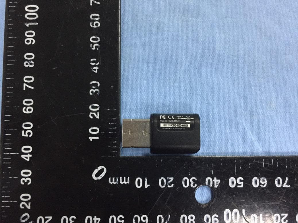
VVXLM842
Feb 18, 2020LM842 WiFi and Bluetooth 5.0 Dual Mode Combination USB Adapter
Equipment Class
DSS - Part 15 Spread Spectrum Transmitter
VVXLM074
Jan 02, 2020LM074 Bluetooth 5.0 Dual Mode Module
Equipment Class
DSS - Part 15 Spread Spectrum Transmitter
VVX-LM820-0462
Oct 25, 2015LM820 Wi-Fi SMT Module 802.11n 150Mbps
Equipment Class
DTS - Digital Transmission System