VWCHDMS9100R433.92MHz Receiver
Antennacraft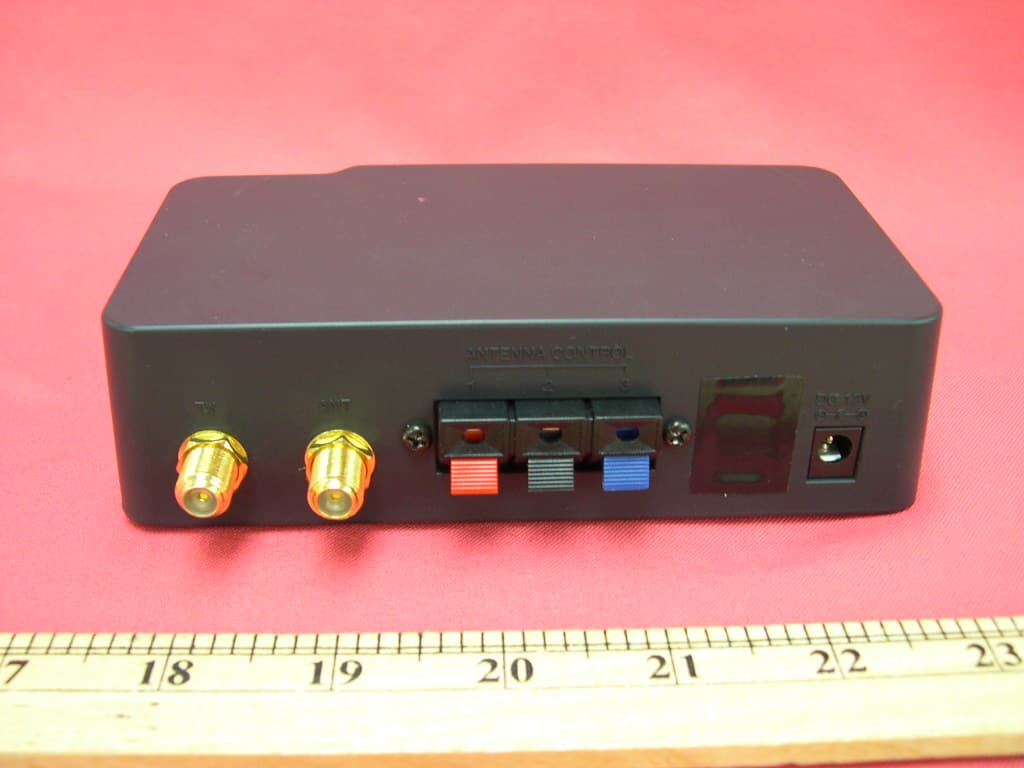
Click to zoom
Application Details
- Equipment Class
- CRR - Superregenerative Receiver
- Date of Grant
- Dec 26, 2007
- Application Purpose
- Original Equipment
- Date of Application
- Dec 26, 2007
- Equipment Note
- 433.92MHz Receiver
- Frequency Range
- 433.92000000 - 433.92000000
- Company
- Antennacraft
- Country
- United States
Documents & Files
Document Text
Text extracted from the exhibit documents filed with the FCC. Open a document above to read the original.
Users Manual
WARNING: INSTALLATION OF THIS PRODUCT NEAR POWERLINES IS DANGEROUS. FOR YOUR SAFETY, FOLLOW THE INSTALLATION DIRECTIONS. Before Installation Note: to CATV SYSTEM INSTALLER—Article 820-40 of the NEC specified that the cable ground shall be connected to the grounding system of the building “as close to the point of cable entry as practical”. Note: Do not plug your Mini-State power supply into an AC outlet or DC power source until all electrical and antenna connections have been made. Doing so may short out the power supply/transformer and void your warranty. CAUTION WARNING: To reduce the risk of fire or electric shock, do not expose this appliance to rain or moisture. RISK OF ELECTRIC SHOCK DO NOT OPEN CAUTION: Use of controls or adjustments or performance of procedures other than those specified may result in hazardous radiation exposure. CAUTION: TO REDUCE THE RISK OF ELECTRIC SHOCK, DO NOT REMOVE COVER (OR BACK). NO USER-SERVICING. REFER ALL SERVICING TO QUALIFIED SERVICE PERSONNEL. The lightning flash with arrowhead symbol, within an equilateral triangle is intended to alert the user to the presence of uninsulated “dangerous voltage” within the product’s enclosure that may be of sig- nificant magnitude to constitute a risk of electric shock to persons. The exclamation point within an equilateral triangle is intended to alert the user to the presence of important operating and maintenance (ser- vicing) instructions in the literature accompanying the appliance. Your Antennacraft HDView360® Mini-State® is perfect for receiving off-air reception. You can store channel positions with the Radio Frequency remote control, then later recall one of the channel memories. Your antenna will automatically go to the direction you programmed for your best reception. The directional, rotating Antenna provides excellent reception of HDTV/VHF/UHF TV channels in most viewing locations. The UV protective housing is made of impact-resistant filled co-polymer, making the exterior resistant to weathering. It features both AC and DC operation and is excellent for use on recreational vehicles, boats, or in the home. MINI-STATE® Antenna System © 2007 ANTENNACRAFT Covered under one or more of the following U.S. Patents: 227,785; 3,721,990; 3,761,333; 3,909,691 • RV • BOAT • HOME with RF remote and Programmable, Direction Memory Model HDMS 9100/RV includes two RV/Boat mounting brackets. Model HDMS 9100 Optional UAM9000 Offset J-Mount The VHF section is a circular shaped, slot tuned, broadband, unidirectional traveling wave antenna. The UHF section is a broadband, multi-element array. Both UHF and VHF signals are amplified with a built-in split-band amplifier that provides up to 20 dB gain. The HDView360 Mini-State Antenna System is designed for long life and requires no routine maintenance. Should the unit ever quit working, refer to the troubleshooting tips to help determine possible causes. Do not attempt to service this product yourself, as opening or removing covers may expose you to dangerous voltage or other hazards. Refer all servicing to qualified service personnel. IMPORTANT—This model is not compatible with Mini-State 5MS series motor drives. ® 1. READ INSTRUCTIONS—All the safety and operating instruc- tions should be read before the appliance is operated. 2. RETAIN INSTRUCTIONS—The safety and operating instruc- tions should be retained for future reference. 3. HEED WARNING—All warnings on the appliance and in the operating instructions should be adhered to. 4. FOLLOW INSTRUCTIONS—All operating and use instructions should be followed. 5. WATER AND MOISTURE—The appliance should not be used near water, for example—near a bathtub, washbowl, kitchen sink, laundry tub, swimming pool, or in a wet basement. 6. VENTILATION—The appliance should be situated so that its location or position does not interfere with its proper ventilation. For example, the appliance should not be situated on a bed, sofa, rug, or similar surface that may block the ventilation open- ings; or, placed in a built-in installation, such as a bookcase of cabinet that may impede the flow of air through the ventilation openings. 7. HEAT—The appliance should be situated away from heat sources such as radiators, heat registers, stoves, or other ap- pliances that produce heat. 8. POWER SOURCES—This product should be operated only from the type of power source indicated on the marking label. If you are not sure of the type of power supply to your home, consult your product dealer or local power company. 9. GROUNDING OR POLARIZATION—This product is equipped with a polarized alternating-current line plug (a plug having one blade wider than the other). This plug will fit into the power outlet only one way. This is a safety feature. If you are unable to insert the plug full into the outlet, try reversing the plug. If the plug should still fail to fit, contact your electrician to replace your obsolete outlet. Do not defeat the safety purpose of the polarized plug. 10. POWER-CORD PROTECTION—Power-supply cords should be routed so that they are not likely to be walked on or pinched by items placed upon or against them, paying particular atten- tion to cords at plugs, convenience receptacles, and the point at which they exit from the appliance. 11. CLEANING—Unplug this product from the wall outlet before cleaning. Do not use liquid cleaners or aerosol cleaners. Use a damp cloth for cleaning. 12. ATTACHMENTS—Do not use attachments not recommended by the product manufacturer as they may cause hazards. 13. ACCESSORIES—Do not place this product on an unstable cart, stand, tripod, bracket, or table. The product may fall, causing serious injury to a child or adult, and serious damage to the product. Use only with a cart, stand, tripod, bracket, or table recommended by the manufacturer, or sold with the product. By mounting of the product should follow the manufacturer’s instructions, and should use a mounting accessory recom- mended by the manufacturer. 14. POW…
Text truncated - open the document above for the full version.
External Photos
INTERTEK TESTING SERVICE Report No.: 07272032 Equipment Photographs Model : HDMS9100 (External) FCC ID: VWCHDMS9100R INTERTEK TESTING SERVICE Report No.: 07272032 Equipment Photographs Model : HDMS9100 (External) FCC ID: VWCHDMS9100R INTERTEK TESTING SERVICE Report No.: 07272032 Equipment Photographs Model : HDMS9100 (without CEA-909) (External) FCC ID: VWCHDMS9100R
ID Label/Location Info
80.0080.00 2 5 . 0 0 2 5 . 0 0 Model: HDMS9100 FCC ID: VWCHDMS9100R Adapter:12V DC, 250mA, Plug Type “M” Custom Manufactured in China for Antennacraft, Burlington, Iowa 52601 This device complies with Part 15 of the FCC Rules. Operation is subject to the following two conditions: (1) This device may not cause harmful interference, and (2) This device must accept any interference received, including interference that may cause undesired operation. Mini-State VHF/UHF/HDTV Antenna System with Remote Control ART NO. REV ECN NO. MODLE ZONE DESCRIPTION DRAFTDATE A PART NO. DWG. NO. PART NAME DEST APPROVED CHECKED DRAFT PLS RETURN IMMEDIATELY AFT FILMED SCALE HDMS9100 R/L (Engraving) Merry 1:1 generated label A/W Merry DATE ES9100P03B 11/01/07 11/01/07 TANDY RADIO SHACK LIMITED A Division of RadioShack Corporation Engraving B Change the FCC ID No. Merry 12/13/07 Receiver
Internal Photos
INTERTEK TESTING SERVICE Report No.: 07272032 Equipment Photographs Model : HDMS9100 (Internal) FCC ID: VWCHDMS9100R INTERTEK TESTING SERVICE Report No.: 07272032 Equipment Photographs Model : HDMS9100 (Internal) FCC ID: VWCHDMS9100R INTERTEK TESTING SERVICE Report No.: 07272032 Equipment Photographs Model : HDMS9100 (Internal) FCC ID: VWCHDMS9100R INTERTEK TESTING SERVICE Report No.: 07272032 Equipment Photographs Model : HDMS9100 (Internal) FCC ID: VWCHDMS9100R INTERTEK TESTING SERVICE Report No.: 07272032 Equipment Photographs Model : HDMS9100 (Internal) FCC ID: VWCHDMS9100R INTERTEK TESTING SERVICE Report No.: 07272032 Equipment Photographs Model : HDMS9100 (Internal) FCC ID: VWCHDMS9100R INTERTEK TESTING SERVICE Report No.: 07272032 Equipment Photographs Model : HDMS9100 (without CEA-909) (Internal) FCC ID: VWCHDMS9100R INTERTEK TESTING SERVICE Report No.: 07272032 Equipment Photographs Model : HDMS9100 (without CEA-909) (Internal) FCC ID: VWCHDMS9100R
Test Report
− The evaluation data of the report will be kept for 3 years from the date of issuance. − This report is for the exclusive use of Intertek's Client and is provided pursuant to the agreement between Intertek and its Client. Intertek's responsibility and liability are limited to the terms and conditions of the agreement. Intertek assumes no liability to any party, other than to the Client in accordance with the agreement, for any loss, expense or damage occasioned by the use of this report. Only the Client is authorized to permit copying or distribution of this report and then only in its entirety. Any use of the Intertek name or one of its marks for the sale or advertisement of the tested material, product or service must first be approved in writing by Intertek. The observations and test results in this report are relevant only to the sample tested. This report by itself does not imply that the material, product, or service is or has ever been under an Intertek certification program. Intertek Testing Services Hong Kong Ltd. 2/F., Garment Centre, 576 Castle Peak Road, Kowloon, Hong Kong. Tel: (852) 2173 8888 Fax: (852) 2785 5487 Website: www.hk.intertek-etlsemko.com Antennacraft Application For Certification (FCC ID: VWCHDMS9100R) Superregenerative Receiver 07272032 TC/el December 20, 2007 INTERTEK TESTING SERVICES FCC ID: VWCHDMS9100R i LIST OF EXHIBITS INTRODUCTION EXHIBIT 1: General Description EXHIBIT 2: System Test Configuration EXHIBIT 3: Emission Results EXHIBIT 4: Equipment Photographs EXHIBIT 5: Product Labelling EXHIBIT 6: Technical Specifications EXHIBIT 7: Instruction Manual EXHIBIT 8: Miscellaneous Information EXHIBIT 9: Confidentiality Request INTERTEK TESTING SERVICES FCC ID: VWCHDMS9100R ii MEASUREMENT / TECHNICAL REPORT Antennacraft − MODEL: HDMS9100 FCC ID: VWCHDMS9100R December 20, 2007 This report concerns (check one:) Original Grant X Class II Change Equipment Type: Superregenerative Receiver (example: computer, printer, modem, etc.) Deferred grant requested per 47 CFR 0.457(d)(1)(ii)? Yes No X If yes, defer until: date Company Name agrees to notify the Commission by: date of the intended date of announcement of the product so that the grant can be issued on that date. Transition Rules Request per 15.37? Yes No X If no, assumed Part 15, Subpart B for unintentional radiator − the new 47 CFR [05-04-07 Edition] provision. Report prepared by: Ho Wai Kin, Ben Intertek Testing Services Hong Kong Ltd. 2/F., Garment Center, 576 Castle Peak Road, Kowloon, Hong Kong. Phone: 852-2173-8505 Fax: 852-2371-0914 INTERTEK TESTING SERVICES FCC ID: VWCHDMS9100R iii Table of Contents 1.0 General Description......................................................................................... 2 1.1 Product Description................................................................................... 2 1.2 Related Submittal(s) Grants ...................................................................... 2 1.3 Test Methodology...................................................................................... 3 1.4 Test Facility ............................................................................................... 3 2.0 System Test Configuration ............................................................................. 5 2.1 Justification ............................................................................................... 5 2.2 EUT Exercising Software .......................................................................... 5 2.3 Special Accessories .................................................................................. 5 2.4 Equipment Modification............................................................................. 6 2.5 Measurement Uncertainty ......................................................................... 6 2.6 Support Equipment List and Description ................................................... 6 3.0 Emission Results ............................................................................................. 8 3.1 Field Strength Calculation ......................................................................... 9 3.2 Radiated Emission Configuration Photograph ........................................ 11 3.3 Radiated Emission Data.......................................................................... 12 3.4 Conducted Emission Configuration Photograph...................................... 15 3.5 Conducted Emission Data....................................................................... 16 4.0 Equipment Photographs ............................................................................... 18 5.0 Product Labelling .......................................................................................... 20 6.0 Technical Specifications ............................................................................... 22 7.0 Instruction Manual ......................................................................................... 24 8.0 Miscellaneous Information ........................................................................... 26 8.1 Stabilization Waveform ........................................................................... 27 8.2 Emissions Test Procedures .................................................................... 28 9.0 Confidentiality Request ................................................................................. 31 INTERTEK TESTING SERVICES FCC ID: VWCHDMS9100R iv List of attached file Exhibit Type File Description Filename Test Report Test Report report.pdf Operation Description Technical Description descri.pdf Test Setup Photo Radiated Emission radiated photos.pdf Test Setup Photo Conducted Emission conducted photos.pdf Test Report Conducted Emission Test Result conducted.pdf External Photo External Photo external photos.pdf Internal Photo Internal Photo internal photos.pdf Block Diagram Block Diagram block.pdf Schematics Circuit Diagram circuit.pdf ID Label / Location Label Ar…
Text truncated - open the document above for the full version.
Test Report
Report No.: 07272032 Receiving mode AC mains Ctrl No.: 150 kHz30 MHz 1 PK CLRWR 2 AV CLRWR SGL TDS 6DB dBμV dBμV RBW 9 kHz MT 1 s PREAMP OFFAtt 10 dB AUTO 1 MHz10 MHz 0 10 20 30 40 50 60 70 80 90 100 CF15MAV CF15MQP Date: 27.NOV.2007 12:02:21 Report No.: 07272032 Receiving mode AC mains Ctrl No.: EDIT PEAK LIST (Final Measurement Results) Trace1: CF15MQP Trace2: CF15MAV Trace3: --- TRACE FREQUENCY LEVEL dBμV DELTA LIMIT dB 1 Quasi Peak 290 kHz 32.63 -27.88 1 Quasi Peak 354 kHz 32.90 -25.96 1 Quasi Peak 406 kHz 29.03 -28.69 1 Quasi Peak 11.59 MHz 30.89 -29.10 Date: 27.NOV.2007 12:02:10 Report No.: 07272032 Antenna Rotating mode AC mains Ctrl No.: 150 kHz30 MHz 1 PK CLRWR 2 AV CLRWR SGL TDS 6DB dBμV dBμV RBW 9 kHz MT 1 s PREAMP OFFAtt 10 dB AUTO 1 MHz10 MHz 0 10 20 30 40 50 60 70 80 90 100 CF15MAV CF15MQP Date: 27.NOV.2007 12:05:56 Report No.: 07272032 Antenna Rotating mode AC mains Ctrl No.: EDIT PEAK LIST (Final Measurement Results) Trace1: CF15MQP Trace2: CF15MAV Trace3: --- TRACE FREQUENCY LEVEL dBμV DELTA LIMIT dB 1 Quasi Peak 290 kHz 33.46 -27.06 1 Quasi Peak 342 kHz 33.38 -25.76 1 Quasi Peak 410 kHz 28.33 -29.31 1 Quasi Peak 11.47 MHz 28.63 -31.36 Date: 27.NOV.2007 12:05:39
Test Report
Job No.: 07272032 FCC ID: VWCHDMS9100R
Test Setup Photos
INTERTEK TESTING SERVICE Report No: 07272032 Configuration Photographs Worst-Case Radiated Emissions (Front View) Model : HDMS9100 Fig.1 FCC ID: VWCHDMS9100R INTERTEK TESTING SERVICE Report No: 07272032 Configuration Photographs Worst-Case Radiated Emissions (Back View) Model : HDMS9100 Fig.2 FCC ID: VWCHDMS9100R
Test Setup Photos
INTERTEK TESTING SERVICE Report No: 07272032 Configuration Photographs Worst-Case Line-Conducted Emissions (Front View) Model : HDMS9100 FCC ID: VWCHDMS9100R i INTERTEK TESTING SERVICE Report No: 07272032 Configuration Photographs Worst-Case Line-Conducted Emissions (Back View) Model : HDMS9100 FCC ID: VWCHDMS9100R ii INTERTEK TESTING SERVICE Report No: 07272032 Configuration Photographs Worst-Case Line-Conducted Emissions (Side View) Model : HDMS9100 FCC ID: VWCHDMS9100R iii
Contact Information
Applicant
Howard Whitcomb(General Manager)
Technical Contact
Intertek Testing Services Hong Kong Ltd.Billy Chow
[email protected](852)2173-8528
2/F., Garment Centre · Kowloon · Hong Kong
Non-Technical Contact
Intertek Testing Services Hong Kong Ltd.Billy Chow
[email protected](852)2173-8528
Test Firm
Intertek Testing Services Hong KongBilly Chow
Technical Specifications
| # | Rule Parts | Frequency Range | Power Output |
|---|---|---|---|
| 1 | 15B | 433.92 MHz - 433.92 MHz | - |
Other Applications from Antennacraft
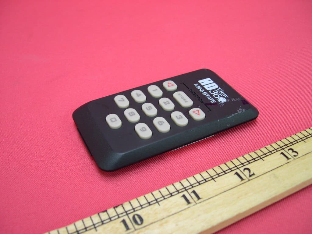
VWCHDMS9100T
Dec 26, 2007Remote Control (433.92MHz Tx)
Equipment Class
DSC - Part 15 Security/Remote Control Transmitter