VXEBM1101R-F Massage Plug System
Bed's and Mo(o)re GmbH u.co.KG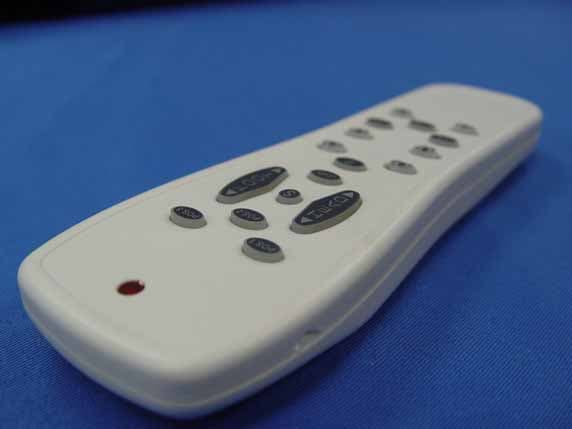
Click to zoom
Application Details
- Equipment Class
- DSC - Part 15 Security/Remote Control Transmitter
- Date of Grant
- Mar 01, 2008
- Application Purpose
- Original Equipment
- Date of Application
- Mar 01, 2008
- Equipment Note
- R-F Massage Plug System
- Frequency Range
- 315.18000000 - 315.18000000
- Country
- Germany
Documents & Files
Document Text
Text extracted from the exhibit documents filed with the FCC. Open a document above to read the original.
Users Manual
Users Manual R-F MASSAGE PLUG SYSTEM MODEL:BM11 Unpacking & Assembling Your Base: Page 1 Section #1 1.Remove the plastic covering from the batteries. Place the (4) AAA batteries in the remote. Verify batteries are properly installed. Push any button on the remote and the background will illuminate when working properly. 2.To synchronize your remote to the control box mounted on the base.Press the “CODE” button on the control-box, “LED” light will be on for 30 seconds, within the allotted time, press the “SET” button on the remote until the “LED” light goes off, this means code-setting between the remote and the controller box was successful. 3. Depress <Head> Up Button on your remote to verify the base operates and the remote is communicating with the control box. If base does NOT operate refer- ence “Synchronizing Your Remote to the Controller Box” in Section 5. 4. Depress ON/OFF “Massage” buttons to turn massage motors on. Depress “Head” Up and “Foot” Up Buttons to verify massage motors are operating properly. READ THE FOLLOWING INFORMATION CAREFULLY BEFORE USING THIS PRODUCT This BetterRest ™ Adjustable Powered Sleep System has been designed with features to assure comfort and safety when operated properly. ELECTRICAL GROUNDING ADVISORY IMPORTANT INFORMATION This product is equipped with a polarized, grounded electrical power cord. The power cord will only fit into a grounded, electrical outlet. WARRANTY WARNING Do not open any control boxes, motors or hand control devices (with the exception of the hand control). The product warranty will be void if these components are tampered with. Do not attempt to alter component wiring or adjust or modify the structure of the product in any way or the warranty will be void. Any repair or replacement of adjustable bed parts must be performed by authorized personnel. LUBRICATION This product is designed to be maintenance free. The lift motors are permanently lubricated and sealed-no additional lubrication is required. Do not apply lubricant to lift motor. PRODUCT RATINGS The bed lift motors are not designed for continuous use. Reliable operation and full life expectancy will be realized as long as the lift motors do not operate any more than three (3) minutes over a thirty (30) minute period, or approximately 18% duty cycle. NOTE: Massage equipped beds are not designed for continuous, extended massage operation. Massage systems are rated for a maximum of 2 hours of use within any 6 hour period. Any attempt to circumvent or exceed product ratings will shorten the life expectancy of the product and may void the warranty. Section #2 interference received, WARNING Page 2 (1)this Device may not cause harmful interference, ust accept any including interference that May cause undesired opration.. adiauseThe manufacturer is not responsible for any ro or TV interference cd by unauthorized ipment.such modification could void the user's authority to operate the equipment FCC Regulation Operation is subject to the following and(2) this device M modeifications to this equ two conditions: This device complles with Part 15 of the FCC rules. For best performance, consumers should enter and exit the adjustable bed with the bed in the flat (horizontal) position. DO NOT SIT ON THE HEAD OR FOOT SECTIONS WHILE IN THE RAISED POSITION. ELECTRICAL COMPONENTS BetterRest ™ Adjustable Powered Sleep System electrical components are rated for 110/120 voltage, 50-60 Hz. SMALL CHILDREN/ PETS WARNING After the foundation is unboxed, immediately dispose of packaging material as it can smother small children and pets. To avoid injury, children or pets should not be allowed to play under or on the bed. Children should not operate this bed without adult supervision. ADVISORY IMPORTANT INFORMATION Section #2 Page 3 Page 4 PRODUCT SPECIFICATIONS Section #3 MAIN POWER SUPPLY110/120v A/C, 50-60 HZ MOTOR OPERATING VOLTAGE24 v D/C with 50 VA transformer with 30 minute cut off MOTOR DUTY CYCLE18% maximum operation 3 minutes MASSAGE MOTORSTwo 24v, 2 variable DC motors, with 30 minute auto shut off REMOTE CONTROL4 x AAA 1.5v batteries BATTERY BACKUP1 x 9v battery Page 5 Remote Control Operation: Section #4 Remote Control Operation Cont’d: To find your chosen position with or without massage, simply press the PROGRAM Key P (Key 8) and your favorite position with or without massage will be attained. Key 5 (HEAD) and Key 6 (FOOT) are for independent adjusting to your chosen angle or degree. The Key 9 and 10 are for independent massage intensity by pressing the ‘upper part’ of the Key 9 and 10 the massage becomes more intense and by pressing the ‘lowerpart’ of the keys the massage becomes less intense. The massage motors are TURNED ON/OFF by pressing the buttons ON/OFF (Keys 11 and 12). User Defined Settings: Keys 13, 14 and 15 are three ‘Pre-Set’ massage programs with different’ massage wave motion’. Massage ModeProgram 1 Massage ModeProgram 2 Massage ModeProgram 3 Note: If massage is utilized in ‘FLAT’ position and ‘MEMORY’ button utilized to save settings then the bed also memorizes the ‘FLAT’ position. TO UNLOCK it press ‘LEVEL’ button. Page 6 Section #4 Pos 1 (Key 1): is a Pre Set Position for ‘Back only’. Pos 2 (Key 2): is a Pre Set Position for ‘Back and Foot only’. Pos 3 (Key 3): is a Pre Set Position for ‘Foot only’. The Set Button (Key 4) has Two main functions. It is used to program Any Remote Hand control to the Black Box by pressing the ‘Key S’ (Key 4) and simultaneously pressing the CODE button (Explained in detail “Synchronizing Your Remote”) on the controller box till the LED light on the box goes out. The user can PRESS ONE Hand control’s S button and have TWO ‘CODE’ buttons simultaneously pressed on TWO Black Boxes (Wait till the LED LIGHTS go OUT) and the user can Now use One hand control to ‘operate’ 2 BetterRest ™ beds simultaneously (no extra cords are needed for 2 Bed Base to operate with ONE hand control). The remote control is now set to operate ONE or TWO beds and mass…
Text truncated - open the document above for the full version.
External Photos
Bed's and Mo(o)re GmbH u.co.KG R-F Massage Plug System FCC ID. : VXEBM1101 EUT External Photos Figure 1 General Appearance (Front & Side View) Figure 2 General Appearance (Back & Side View)
ID Label/Location Info
Bed's and Mo(o)re GmbH u.co.KG R-F Massage Plug System FCC ID. : VXEBM1101 FCC ID Label Location z Label Placement Location z FCC Label Format FCC Label Placement Location
Internal Photos
Bed's and Mo(o)re GmbH u.co.KG R-F Massage Plug System FCC ID. : VXEBM1101 EUT Internal Photos Figure 3 Internal View (Removed Cover) Figure 4 Internal View (Control Board, Front View) Bed's and Mo(o)re GmbH u.co.KG R-F Massage Plug System FCC ID. : VXEBM1101 Figure 5 Internal View (Control Board, Front View) Figure 6 Internal View (Control Board, Back View) Bed's and Mo(o)re GmbH u.co.KG R-F Massage Plug System FCC ID. : VXEBM1101 Figure 7 Internal View (Control Board, Back View) Figure 8 Internal View
Test Report
FCC ID. VXEBM1101 Page 1 of 23 AUDIX Technology Corporation Report No.: EM-F970112 TEST REPORT FOR CERTIFICATION On Behalf of Bed's and Mo(o)re GmbH u.co.KG R-F Massage Plug System (Transmitter Unit) Model No.:BM11 FCC ID:VXEBM1101 Prepared for : Bed's and Mo(o)re GmbH u.co.KG Jahnstr 12, 32049 Herford Germany Prepared by : AUDIX Technology Corporation EMC Department No. 53-11, Tin-Fu Tsun, Lin-Kou Hsiang, Taipei Hsien, Taiwan Tel : (02) 2609-9301, 2609-2133 Fax : (02) 2609-9303 File Number : EM970287 Report Number : EM-F970112 Date of Test : Feb. 19, 2008 Date of Report : Feb. 26, 2008 FCC ID. VXEBM1101 Page 2 of 23 AUDIX Technology Corporation Report No.: EM-F970112 TABLE OF CONTENTS Description Page TEST REPORT CERTIFICATION ....................................................................................................3 1. GENERAL INFORMATION ..........................................................................................................4 1.1. Description of Device (EUT) .................................................................................................................. 4 1.2. Description of Test Facility..................................................................................................................... 5 1.3. Measurement Uncertainty ....................................................................................................................... 5 2. CONDUCTED EMISSION MEASUREMENT .............................................................................6 3. RADIATED EMISSION MEASUREMENT .................................................................................7 3.1. Test Equipment ....................................................................................................................................... 7 3.2. Test Setup................................................................................................................................................ 7 3.3. Radiation Emission Limits (§15.209 & 15.231) ..................................................................................... 8 3.4. EUT’s Configuration during Compliance Measurement ........................................................................ 8 3.5. Operating Condition of EUT................................................................................................................... 9 3.6. Test Procedure......................................................................................................................................... 9 3.7. Radiated Emission Measurement Results ............................................................................................. 10 4. EMISSION BANDWIDTH MEASUREMENT ...........................................................................15 4.1. Test Equipment ..................................................................................................................................... 15 4.2. Block Diagram of Test Setup ................................................................................................................ 15 4.3. Specification Limits (§15.231-(c))........................................................................................................ 15 4.4. EUT’s Configuration during Compliance Measurement ...................................................................... 15 4.5. Emission Bandwidth Measurement Results..........................................................................................15 5. PERIODIC OPERATED MEASUREMENT ..............................................................................17 5.1. Test Equipment ..................................................................................................................................... 17 5.2. Block Diagram of Test Setup ................................................................................................................ 17 5.3. Specification Limits [§15.231-(a)-(1)].................................................................................................. 17 5.4. EUT’s Configuration during Compliance Measurement ...................................................................... 17 5.5. Periodic Operated Measurement Results .............................................................................................. 17 6. DEVIATION TO TEST SPECIFICATIONS...............................................................................19 7. PHOTOGRAPHS............................................................................................................................20 7.1. Photos of Radiated Measurement at Semi-Anechoic Chamber ............................................................ 20 7.2. Photo of Emission Bandwidth Measurement ........................................................................................23 7.3. Photo of Periodic Operated Measurement ............................................................................................ 23 FCC ID. VXEBM1101 Page 3 of 23 AUDIX Technology Corporation Report No.: EM-F970112 TEST REPORT CERTIFICATION Applicant : Bed's and Mo(o)re GmbH u.co.KG Manufacturer : Bed's and Mo(o)re GmbH u.co.KG EUT Description : R-F Massage Plug System FCC ID : VXEBM1101 (A) MODEL NO. : BM11 (B) SERIAL NO. : N/A (C) POWER SUPPLY : DC 6V (Battery) (D) TEST VOLTAGE : DC 6V (Via four AAA Batteries) Measurement Procedure Used: FCC RULES AND REGULATIONS PART 15 SUBPART C, Sep. 2007 AND ANSI C63.4/2003 (FCC CFR 47 Part 15C, §15.207, §15.209 and §15.231) The device described above was tested by AUDIX Technology Corporation to determine the maximum emission levels emanating from the device. The maximum emission levels were compared to the FCC Part 15 subpart C limits both radiated and conducted emissions. The measurement results are contained in this test report and AUDIX Technology Corporation is assumed full responsibility for the accuracy and completeness of these measurements. Also, this …
Text truncated - open the document above for the full version.
Test Setup Photos
FCC ID. VXEBM1101 Page 20 of 23 AUDIX Technology Corporation Report No.: EM-F970112 7. PHOTOGRAPHS 7.1. Photos of Radiated Measurement at Semi-Anechoic Chamber 7.1.1. Frequency Range 30MHz~1GHz Position: EUT on Stand Position: EUT on Side FCC ID. VXEBM1101 Page 21 of 23 AUDIX Technology Corporation Report No.: EM-F970112 Position: EUT on Lying 7.1.2. Frequency Above 1GHz Position: EUT on Stand FCC ID. VXEBM1101 Page 22 of 23 AUDIX Technology Corporation Report No.: EM-F970112 Position: EUT on Side Position: EUT on Lying FCC ID. VXEBM1101 Page 23 of 23 AUDIX Technology Corporation Report No.: EM-F970112 7.2. Photo of Emission Bandwidth Measurement 7.3. Photo of Periodic Operated Measurement
Contact Information
Applicant
Frank. Liebl(Electronic Engineer)
Test Firm
Audix Technology CorporationLeon Liu
Technical Specifications
| # | Rule Parts | Frequency Range | Power Output |
|---|---|---|---|
| 1 | 15.231 | 315.18 MHz - 315.18 MHz | - |